
Abstract
Under small amplitude and medium-high frequency excitations, mechanical properties of squeeze mode magnetorheological (MR) damper change obviously which are different from general properties. Performance will be attenuated seriously which is known as the high frequency hardening effect. In this paper, mechanical performance of a novel squeeze mode MR damper with pre-compression mechanism under such excitations has been analyzed qualitatively and quantitatively. A novel squeeze mode MR damper with pre-compression mechanism is proposed to improve performance. Then, considering viscoelasticity, inertial effect and pre-compression, an optimized model has been proposed which can precisely describe the performance under such excitations. Comparing with experimental results, performances of squeeze mode MR damper under such excitations are quite different from general properties. The damping force decreases gradually without a sudden decrease at the maximum stroke and it shows stiffness characteristics obviously. What’s more, the maximum damping force is up to 1916 N with an increase of 321.6% at the current of 1 A and frequency of 10 Hz. The energy dissipation is increased by 342% with pre-compression of 1 MPa. The damping force and energy dissipation increase rapidly with increasing the pre-compression. Experimental results demonstrate that the high frequency hardening effect is effectively improved by pre-compression.
Keywords
1. Introduction
During the past few decades, magnetorheological (MR) fluid has been used in various engineering fields due to fast respond within only milliseconds and large output force (Choi et al., 2016; Yu et al., 2022). The viscosity of MR fluid changes rapidly by the applied currents which is called the MR effect (de Vicente et al., 2011). MR damper is the typical application which has been analyzed in semi-active vibration control system (Nguyen et al., 2018; Raja et al., 2014; Song et al., 2017). According to the working principle, MR dampers can be divided into three modes including valve, shear and squeeze modes. MR damper with squeeze mode can produce larger force under small amplitude than other MR dampers (Yazid et al., 2014). It is more suitable in important engineering fields, like precision device (Li et al., 2018) and whole-spacecraft isolation (Kawak, 2017). These conditions require well performance under small amplitude (within 1 mm) (Dong et al., 2022; Yang et al., 2019) and medium-high frequency (above 10 Hz) (Phu et al., 2014). However, conventional squeeze mode MR damper mostly works at low frequency which is lower than 10 Hz in practical applications (Chen et al., 2016). When working frequency is larger than 10 Hz, high frequency hardening effect cannot be avoided and output performance will be attenuated. Comparing with other MR dampers, squeeze mode MR damper has a better performance under such excitations. Investigations with squeeze mode MR damper mainly focus on two parts.
The first part is the optimization of damping force within a compact configuration. The finite element method magnetic (FEMM) was used to improve the magnetic flux density of annular gap and damping force (Patel and Patel, 2018). The co-simulation optimal platform with the non-dominated sorting genetic algorithm II (NSGA-II) was adopted to solve the optimal solutions of squeeze mode MR damper (Li et al., 2016). What’s more, the mixed mode MR damper is an effective way to improve output performance (Yazid et al., 2014). MR damper with squeeze-valve bi-modes had been designed to improve the mechanical properties and working life (Ruan et al., 2020). However, there are still some problems including complex structure and fabrication difficulty with squeeze mode MR damper. The second part is the modeling of hysteresis characteristics with squeeze mode MR damper. Bingham plastic model is the simplest model to describe the dynamic performance of MR fluid (Meng et al., 2019). This model ignores the pre-yield viscoelastic properties. Subsequently, quasi-static models have been developed to improve the accuracy, such as the nonlinear bi-viscous model (Wereley et al., 1998), Herschel-Bulkley model (Wang and Gordaninejad, 2007), Bouc-Wen model (Wen, 1976), and hyperbolic tangent model (Kwok et al., 2006). What’s more, a current-dependent hysteresis model was developed considering the gap width and inertial effect (Chen et al., 2017). The non-convex constitutive relation was also used in modeling of squeeze mode MR damper (Wang et al., 2021). Besides these, some non-parametric models have been used to capture the characteristics (Du et al., 2006; Zong et al., 2012). These models are more complicated. It’s difficult to confirm identification parameters.
Many investigations have been carried out with squeeze mode MR damper. However, there are still some problems which are urgent to be solved, such as theoretical modeling and performance optimization. Performance of squeeze mode MR damper needs to be further studied under small amplitude and medium-high frequency excitations.
Firstly, the theoretical model with squeeze mode MR damper should be further analyzed. In previous literature, investigations focus on the performance evaluation and magnetic circuit optimization (Gong et al., 2014; Ruan et al., 2020; Sapiński and Gołdasz, 2015; Yazid et al., 2016). The characteristic models with damping force are seldom developed of squeeze mode MR damper. Based on the nonlinear bi-viscous model, a mathematical model of squeeze pressure was proposed which had a large error with small current (Yao et al., 2015). In order to improve accuracy of modeling, the inertial effect was used to build an effective model (Zhang et al., 2011). What’s more, based on the continuum media theory, the fluid inertia and hysteresis property were considered into a novel theoretical model (Chen et al., 2016). However, MR fluid mainly works in pre-yield region under such excitations. Most of research works only analyze the viscous force, inertial force and controllable MR effect. The viscoelasticity in pre-yield region of MR fluid has been ignored frequently. Boundary conditions are always simplified to a constant. The accuracy of theoretical models should be improved.
Secondly, mechanical properties of squeeze mode MR damper under small amplitude and medium-high frequency should be further analyzed. Squeeze mode MR damper is mostly used in low-frequency vibration isolating system in practical fields, like civil structure and vehicle suspension (Chen et al., 2016). Comparing with most research works, the minimum amplitude in the experiments of squeeze mode MR damper is larger than 1 mm and the working frequency is less than 10 Hz (Farjoud et al., 2009; Resch et al., 2010). A squeeze mode MR damper was designed and tested. The maximum damping force is 4200 N with the amplitude of 1.44 mm and frequency of 1 Hz (Sapiński and Gołdasz, 2015). Only few investigations have been carried out with the smaller amplitude and medium-high frequency. A novel squeeze mode MR damper was tested under the amplitude of 0.5 mm and frequency of 8 Hz (Meng et al., 2019). Comparing with different experiments, MR dampers had been tested with the minimum amplitude of 0.3 mm and maximum frequency of 1 Hz (Gong et al., 2014; Ruan et al., 2020). However, in some critical applications, such as precision devices and satellite, excitation amplitude is less than 0.3 mm and the frequency is larger than 10 Hz. Output performance of squeeze mode MR damper is rarely analyzed and modeled under such excitations. Mechanical property changes rapidly which should be considered into the theoretical model.
Thirdly, the high frequency hardening effect of squeeze mode MR damper should be optimized. It is known that squeeze mode MR damper is suitable for small amplitude. Hence, the so-called high frequency hardening effect is unavoidable under such excitations (Phu and Choi, 2019). It means that the dynamic stiffness of MR damper increases significantly and the vibration isolating performance will be deteriorated under such excitations (Nguyen et al., 2013). In order to solve this problem, a flexible plate was used in a squeeze-valve mode MR damper. Output performance was improved at the frequency of 10 Hz (Phu et al., 2014). The inclined gap of the piston was developed to prevent this effect (Zheng et al., 2017). Besides these, the squeeze strengthening effect caused by pre-compression is an effective way to solve this critical problem. The energy dissipation was improved with an increase of 43.5% (Dong et al., 2022). However, the squeeze strengthening effect is mostly used to improve performance of MR fluid. Strengthening effect is rarely analyzed in MR dampers. Then, it is noted that the high frequency hardening effect is the same with block-up behavior. Therefore, it is a common problem with various MR dampers. It’s essential to solve the high frequency hardening effect for improving output performance.
On the basis of these motivations, the main aims of this paper are the modeling, evaluation and optimization of a novel squeeze mode MR damper under small amplitude and medium-high frequency. The high frequency hardening effect under such excitations is improved significantly by pre-compression. What’s more, the flow mechanism of MR fluid of squeeze mode MR damper has been discussed to analyze the unique characteristics. In this paper, a novel squeeze mode MR damper with pre-compression mechanism is proposed in Section 2. Based on the continuum media theory, a theoretical model with pre-compression, inertial force and viscoelasticity of squeeze mode MR damper has been derived in Section 3. Experiments have been carried out to validate the correctness of the proposed model. Comparing with experimental results, the flow mechanism and output performance of the proposed MR damper have been analyzed deeply under such excitations in Section 4. Conclusions are listed in Section 5.
2. Mechanism configuration
For the sake of analysis with mechanical properties of squeeze mode MR damper under small amplitude and medium-high frequency excitations and validation of the improvement caused by pre-compression, a novel squeeze mode MR damper with the pressure controlled mechanism is proposed in Figure 1. The squeeze plate moves up and down under different strokes. MR fluids in upper and lower gaps are compressed in compression and tension strokes. MR fluids in these gaps work in the squeeze mode. In flow channel, MR fluid flows along vertical direction and works in the shear mode. However, the gap width is so large that the generated damping force can be ignored. Therefore, the proposed MR damper can be regarded as the squeeze mode MR damper. It can generate a large damping force under the excitation of small amplitude.
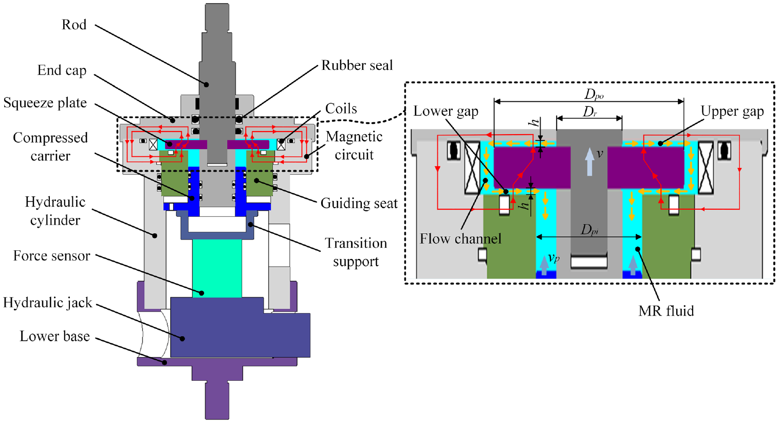
Configurations of the proposed squeeze mode MR damper.
The proposed MR damper consists of the rod, the squeeze plate, the hydraulic cylinder, the guiding seat, force sensor and the compressed carrier, etc. As shown in Figure 1, the working principle of the proposed MR damper have been analyzed. The magnetic circuit is generated by a single electromagnetic coil. The coil is fixed by cage. Magnetic induction lines pass through the lower and upper gaps. Two gaps near the squeeze plate are working regions. When the squeeze plate moves upward, MR fluid in the upper gap will be compressed. And then, MR fluid flows through the working region along the radial direction of the squeeze plate. On the contrary, the lower gap will be compressed when the squeeze plate moves downward. The magnetic particle chains are broken and MR fluid has been yielded with the motion of the plate. Damping force of squeeze mode MR damper can be controlled by the applied current.
What’s more, a pressure controlled mechanism has been added into the proposed MR damper to change the working pressure of MR fluid. The pre-compression of MR fluid can be achieved by the hydraulic jack. With the movement of the hydraulic jack, the compressed carrier moves synchronously with the same direction and velocity. The total volume of MR fluid decreases. Therefore, MR fluid is compressed and the initial pressure is adjustable. The squeezing force is measured by the internal force sensor. The pressure can be calculated by the tested force. The squeeze strengthening effect with this MR damper can be achieved and enhanced by the proposed mechanism.
Sealing mechanism consists of multistage series sealing in upper and lower gaps. Step seal has been used to ensure good performance of sealing. When pre-compression is applied, well seal effect can be obtained.
The magnetic flux density of working region is the key parameter for the output performance of squeeze mode MR damper. In order to improve the magnetic flux density and keep the uniform distribution of magnetic field in the working regions, simulations with different gap distances have been carried out by ANSYS Workbench. The gap distance with working regions changes from 0.5 to 2 mm with a step of 0.5 mm. The three-dimensional structure of the proposed MR damper can be simplified into a two-dimensional axisymmetric model due to the revolving characteristics. The adaptive mesh division has been used to analyze the magnetic flux density. The value of convergence is 2% to satisfy the accuracy. The results of FEA are shown in Figure 2 with the gap of 0.5 mm and the applied current of 2 A. The distributions of the magnetic flux density with different gap distances have been shown in Figure 3.
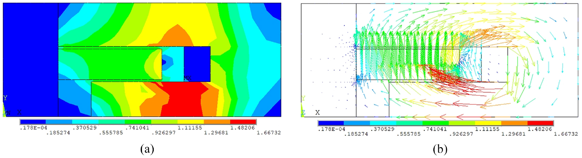
Cloud diagrams of magnetic fields with the proposed MR damper: (a) distribution of magnetic flux density and (b) magnetic flux path.
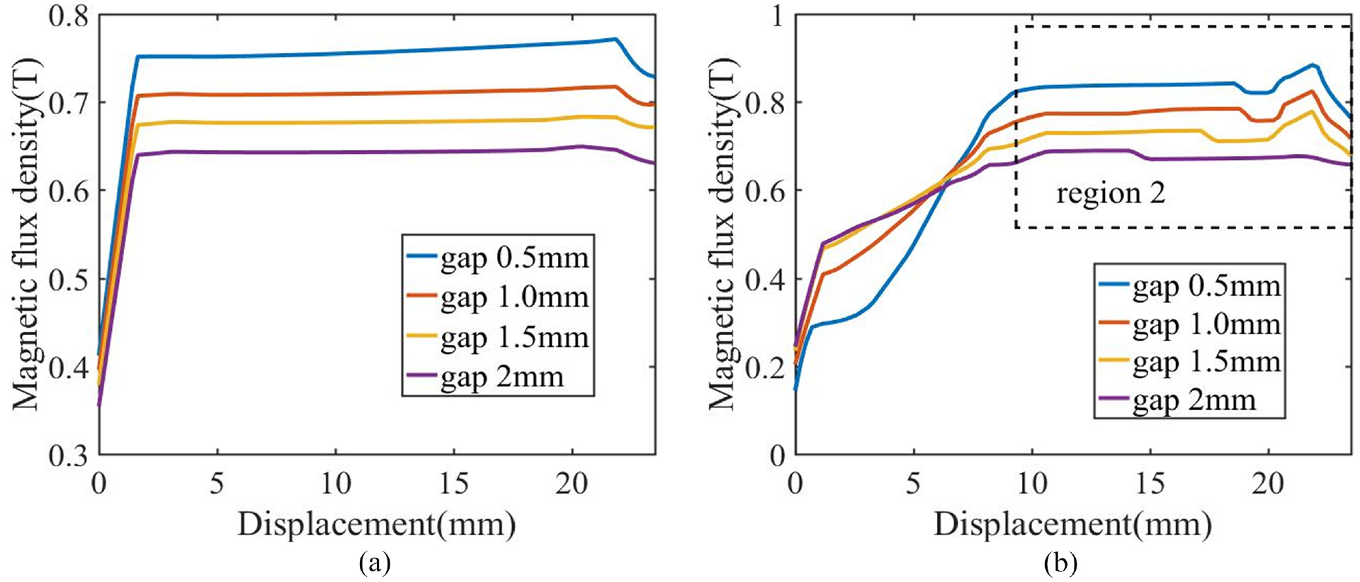
Magnetic flux densities in different working regions: (a) upper gap and (b) lower gap.
According to the simulation results, the magnetic fields pass through the upper and lower gaps. The magnetic flux density of two working regions increases with the decrease of the gap distance. When the gap distances of two working regions are 0.5 mm, the maximum magnetic flux density is 0.84 T. The average magnetic flux density of the upper gap is significantly less than the lower gap. The main reason is the decrease of the section-area which is caused by the non-magnetic compressed carrier. In addition, there are some sudden changes in the edges of squeeze plate in Figure 3. This phenomenon is caused by the different permeability of non-magnetic components. However, these regions are so small that can be ignored. The magnetic flux density can be regarded as the uniform distribution in two working regions. It is essential to maintain a stabilized output performance.
3. Theoretical analysis
To analyze the mechanical performance of squeeze mode MR damper under small amplitude and medium-high frequency, a physical model has been derived and analyzed in this section. The structure of the proposed MR damper is divided into four working regions in Figure 4. When the amplitude is small, the high frequency hardening effect is difficult to be avoided and MR fluid will not flow through the gap. MR fluid works in pre-yield region which shows the viscoelasticity under this condition. Therefore, the Bi-plastic Bingham model has been used to analyze the flow mechanism under such excitations.
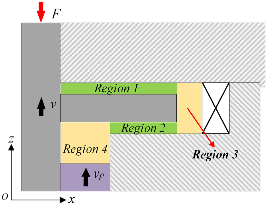
Analysis of working regions with the proposed MR damper.
The Bi-plastic Bingham model is shown in equation (1).
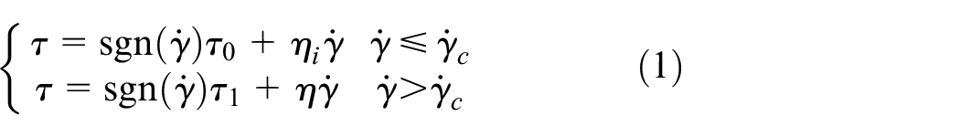
Where τ is shear stress under different excitations. ηi, η are viscosity with pre-yield region and post-yield regions, respectively. τ0, τ1 are the initial yield stress with pre-yield and post-yield regions of MR fluid, respectively.
The magnetic circuits pass through the regions 1 and 2 uniformly. Magnetic damping force should be considered in the physical model. The viscous and inertial effect in all regions are essential with damping force under small amplitude and medium-high frequency. Then, the total damping force of the proposed MR damper is shown as

Where F is the total damping force. Fm is the magnetic damping force generated by MR effect. Fi is the inertial force of MR fluid. Fη is the viscous damping force with all working regions. f is the friction force of the proposed MR damper.
According to the Reynolds number of the upper and lower gaps, the flow of MR fluid can be regarded as the laminar flow (Dong et al., 2022). The distributions of the velocity and shear stress in working regions are shown in Figure 5. In the modeling of the proposed MR damper, the normal force caused by the magnetic field gradient and minor loss have been ignored.
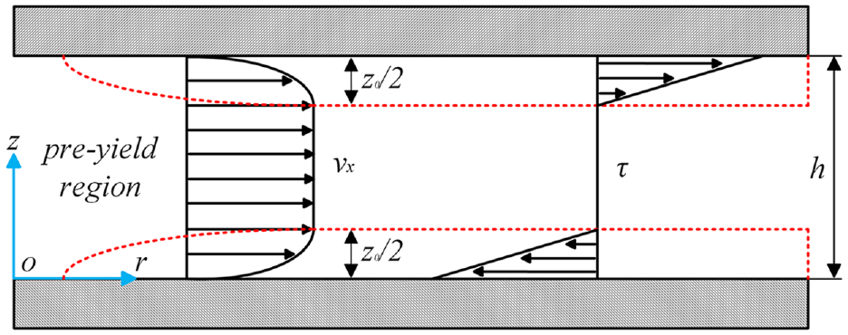
Gradient distributions of MR fluid in squeeze mode MR damper.
Based on the Navier-Stokes’ equation, the flow of MR fluid can be simplified to a one-dimensional equation under this condition along the radial direction.
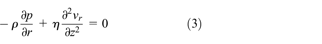
Where ρ is density of MR fluid. p is the fluid pressure. vr is the velocity of MR fluid. η is the viscosity of MR fluid. The gap distance in working regions maintains the same and the deformation of the squeeze plate is ignored. Equation (3) can be simplified.
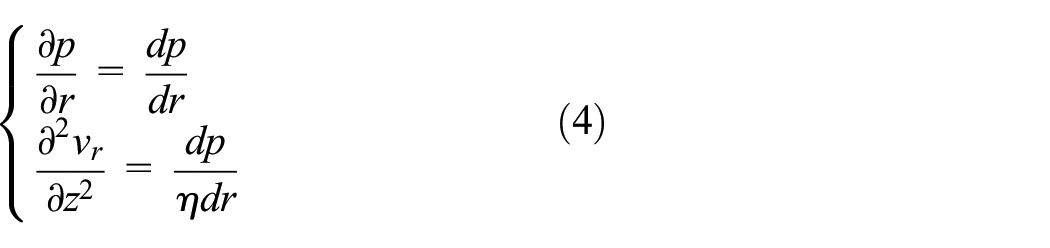
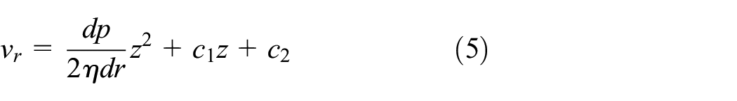
According to the distributions of velocity, the pre- and post-yield regions are analyzed separately. In post-yield region, considering the boundary condition of vr = 0 when z = 0 or z = h, the distribution of velocity can be obtained.
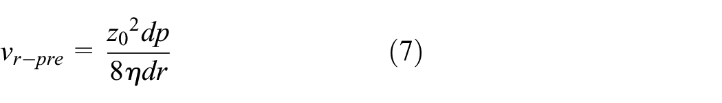
In pre-yield region, MR fluid works as the Newtonian fluid. The boundary condition is vr (z = z0/2) = vr (z = h−z0/2). Satisfying the boundary condition leads to the velocity in this region.
Where z0 is the thickness of MR fluid in post-yield region. The thickness can be obtained by N-S equation which is shown as
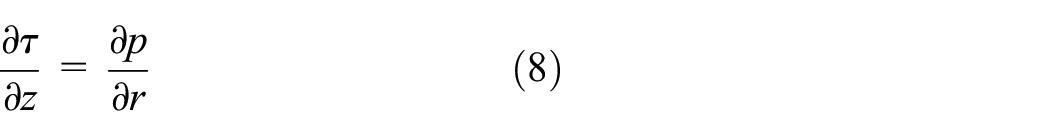
Combined with the boundary condition, shear stress can be derived as follows
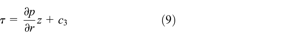
Where c3 is the integration constant. It can be determined by the boundary condition which is shown as

Based on above derivations, the thickness of pre-yield region can be shown as
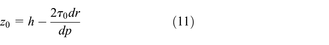
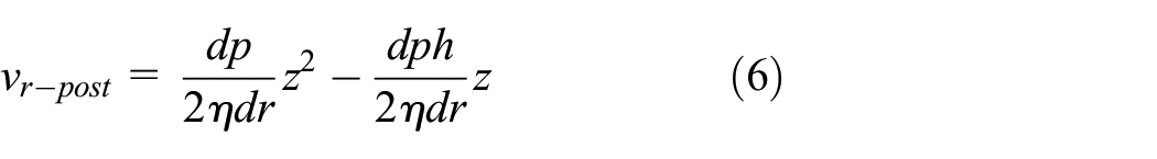
Substituting equation (11)–(7), the velocity of MR fluid can be described as
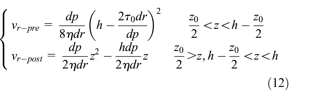
According to the flux conservation law of MR fluid, the flow rate q can be derived as
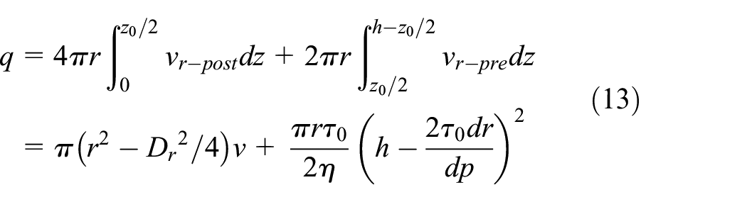
Where Dr is the diameter of the rod. v is the vertical velocity of the squeeze plate. Based on the flow rate in the working gap, the distribution of the fluid pressure combined with the boundary condition (when r = R, p = 0) can be derive as
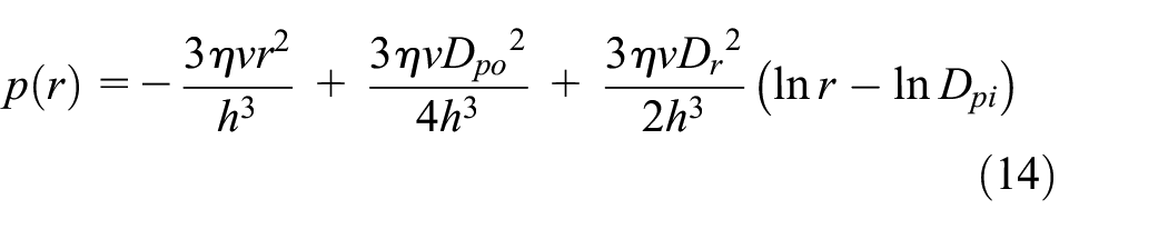
Where h is the gap distance. Dpo is the outer diameter of squeeze plate. According to equation (14), the viscous damping force in squeezed regions can be obtained by numerical integration.
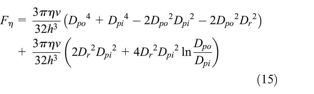
Where Dpi is the internal diameter of guiding seat which means the effective regions in the lower gap.
At the excitations of small amplitude and medium-high frequency, inertial effect has an important influence to the output performance. Based on the theory of lubrication, the governing equation of MR fluid is shown as
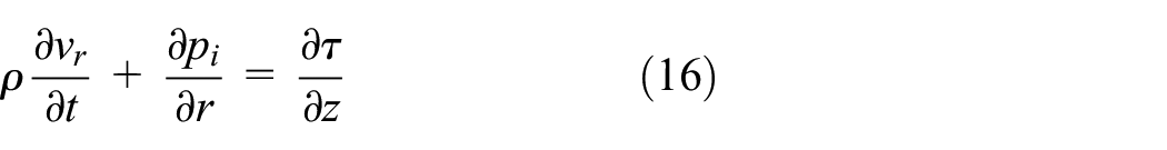
Where pi is the pressure generated by the inertial force. Combined with the boundary conditions, the pressure drop pi can be derived by integration.
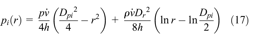
According to equation (17), the inertial force can be obtained.
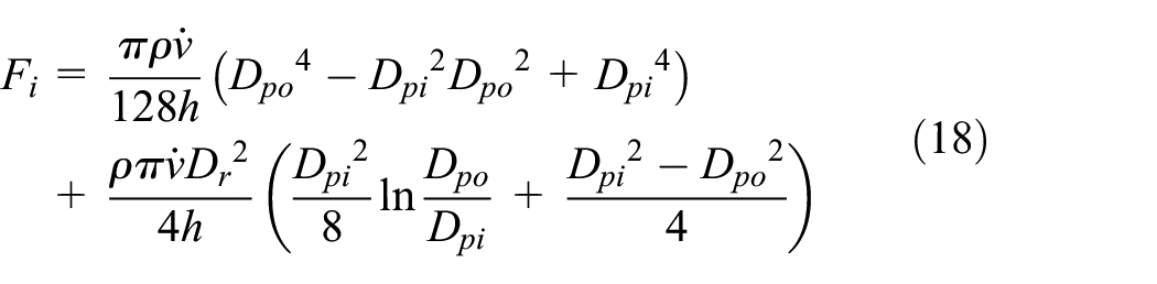
What’s more, MR fluid has been considered as Bingham fluid generally. However, squeeze mode MR damper mainly focuses on the small amplitude. MR fluid is working in the pre-yield and post-yield regions. Bingham model is only used for the post-yield region. So the Bi-plastic Bingham model has been used in this section. The pressure gradient generated by MR effect is derived as
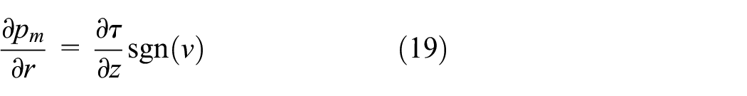
Where pm is the pressure generated by MR effect. The plug flow region is located in the middle of gaps as shown in Figure 5. The shear stress is essential to damping force. According to the related literature (Yao et al., 2015), the boundary condition with pre-yield region can be obtained as
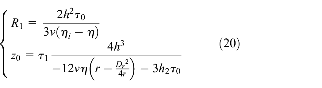
The coefficient of yield surface can be derived as
Based on the boundary condition of post-yield regions, shear stress can be derived as
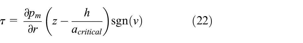
The pressure pm can obtained by integration.
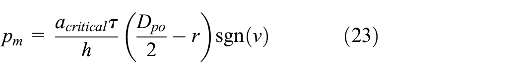
So the magnetic controllable damping force is derived as
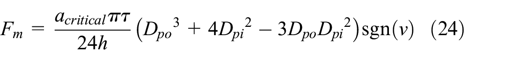
Besides these, the pre-compression should be considered into the theoretical model. With the movement of the compressed carrier, the initial pressure with MR fluid will be changed. According to previous literature, yield stress increases with the increase of the pre-compression. In this model, the improved shear yield stress can be derived as

Where τp is the improved shear yield stress. Kf is a coefficient with the pre-compression. ps is the initial pressure by the pre-compression. The pressure drop caused by the change of the volume is ignored in this model. The improved magnetic damping force is derived as
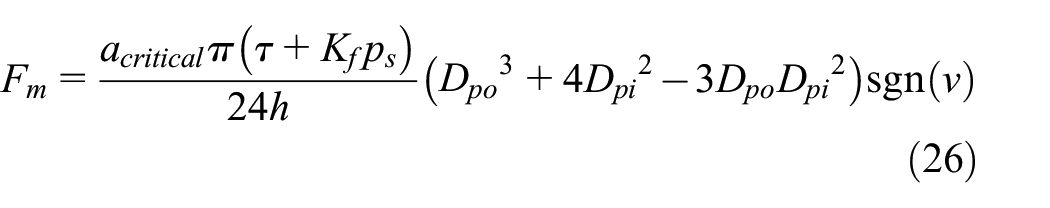
Substituting equations (15), (18), (26) into equation (2), the total damping force with the proposed squeeze mode MR damper can be derived as
Comparing with the conventional squeeze MR damper, the effective working regions with upper and lower gap are different in the proposed MR damper. Due to the difference of the working gap, the magnetic flux density of the lower gap is larger than the upper gap. Therefore, the damping force of compression is significantly larger than the force of tension. The damping force of tension can be obtained by replacing the geometrical parameters.
4. Experimental test and discussion
4.1. Magnetic properties and experimental set-up
In order to evaluate the performance of the proposed MR damper and validate the correctness of the theoretical model, the FEA has been carried out to analyze the distribution of the magnetic field. Geometrical parameters of the proposed MR damper have been optimized by modeFrontier to keep the balance between the magnetic flux density and adjusting range. The geometrical parameters are listed in Table 1. The measured resistance of this single coil is 2.3 Ω with the turns of 63. Meanwhile, MR fluid of G28 (MRF-G28, Chongqing Material Research Institute Co., Ltd.) is selected as the damping liquid in the proposed MR damper. The fundamental configurations of MR fluid and other materials are listed in Table 2.
Geometrical parameters of the proposed MR damper.
Basic configurations of materials.
Considering the convergence of the FEA results, the two-dimensional model of the proposed MR damper has been analyzed with the different applied currents. The distribution of magnetic flux density and magnetic flux path are shown in Figure 6 when the current of 2.0 A is applied. The average values of magnetic flux density with two working regions are 0.69 and 0.75 T, respectively. It meets with the practical requirement to provide enough damping force. The distributions of the magnetic flux density are shown in Figure 6. There are fluctuations of magnetic fields in the edge of the squeeze plate which can be ignored. The magnetic flux density is concentrated in the working regions uniformly. The magnetic flux density of region 2 is larger than region 1. This is caused by the decreases of effective area in region 2. Most magnetic fields concentrate in a smaller region.
Distributions of magnetic flux density with the proposed MR damper: (a) cloud diagrams of magnetic flux density, (b) magnetic flux path, and (c) magnetic flux densities with different regions.
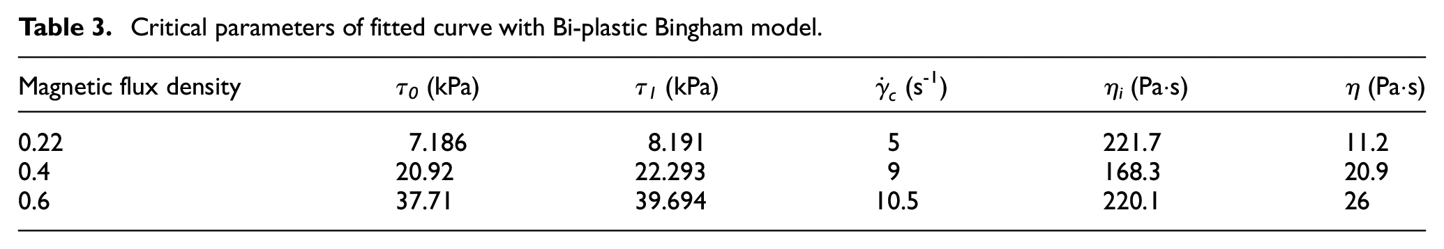
The properties of MR fluid with G28 have been measured via changing the magnetic flux density from 0 to 0.75 T with an increase of 0.1 T using the Physical MCR 302 parallel plate rheometer (Anton Paar, Austria). The tested results are shown in Figure 7. Based on the Bi-plastic Bingham model, the function has been fitted by MATLAB. The fitted curves are shown in Figure 7. Comparing with the measured results of MR fluid, the fitted curve can be employed to characterize the change law of shear stress accurately. Some critical parameters of fitted curve with Bi-plastic Bingham model are shown in Table 3.
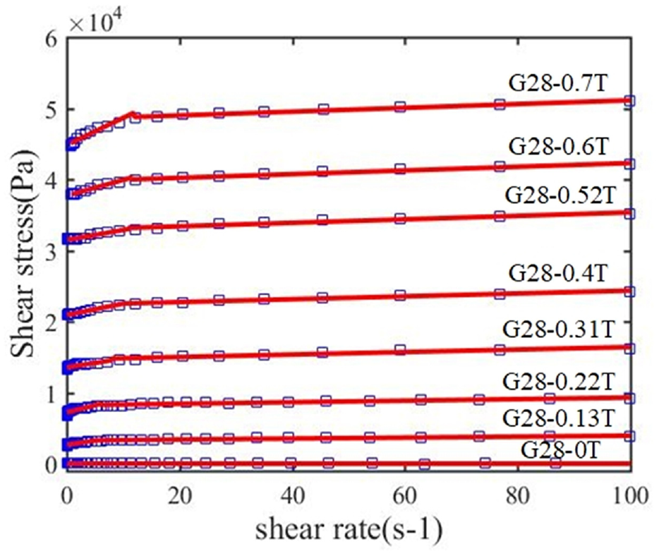
Comparisons between fitted and measured results with different magnetic flux densities.
Critical parameters of fitted curve with Bi-plastic Bingham model.
According to the optimized parameters of the proposed MR damper, the prototype of the squeeze mode MR damper has been manufactured and tested by the Mechanical Test System (MTS 370.10). The components of the proposed MR damper and the performance test experiments with the prototype are shown in Figure 8. It consists of the MR damper, DC power and hydraulic jack, etc. The DC power device (E3631A, Agilent, American) is used to supply the regular current from 0 to 2.5 A. The hydraulic jack provides external force to change the initial pressure by the movement of the compressed carrier. The squeezing force is measured by the force sensor (DYMH-102, Daysensor Co., Ltd., China) with the range of 0–5 T. The desired pre-compression is calculated by the measured force. The specific pressure can be obtained by adjusting the force. The experimental results with displacement, time and output force will be recorded automatically by the self-contained sensors.
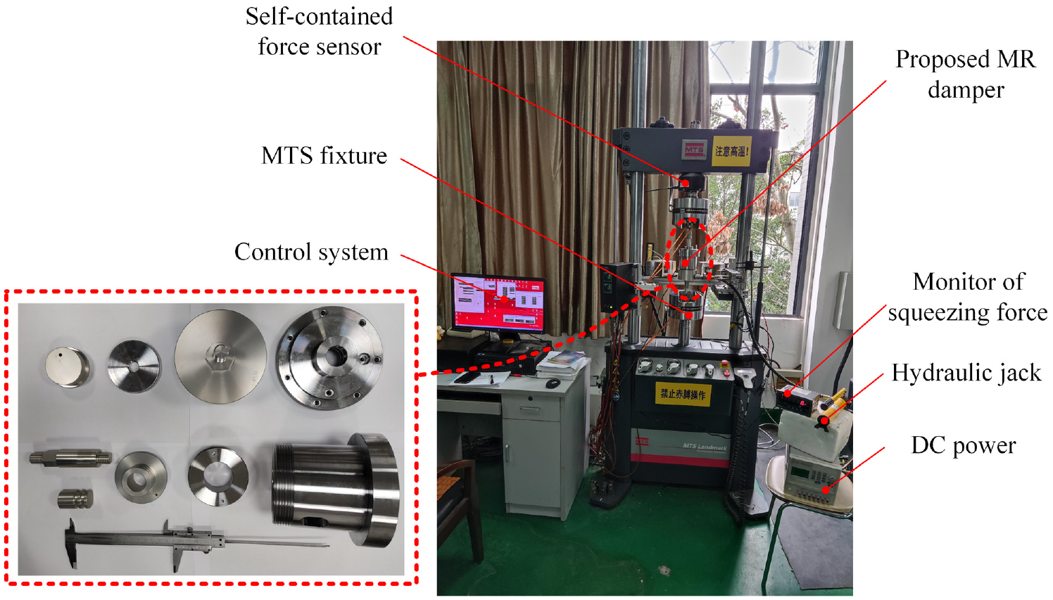
Experimental set-up with the proposed MR damper.
4.2. Seal friction force test
In general, two performance tests should be carried out with MR damper including the seal friction force test and performance test under different excitations. Firstly, the seal friction force of the proposed MR damper has been measured by inputting a very low velocity of 0.016 mm/s triangular wave. Viscous damping force can be ignored under this velocity. The experimental result of seal friction force is shown in Figure 9.
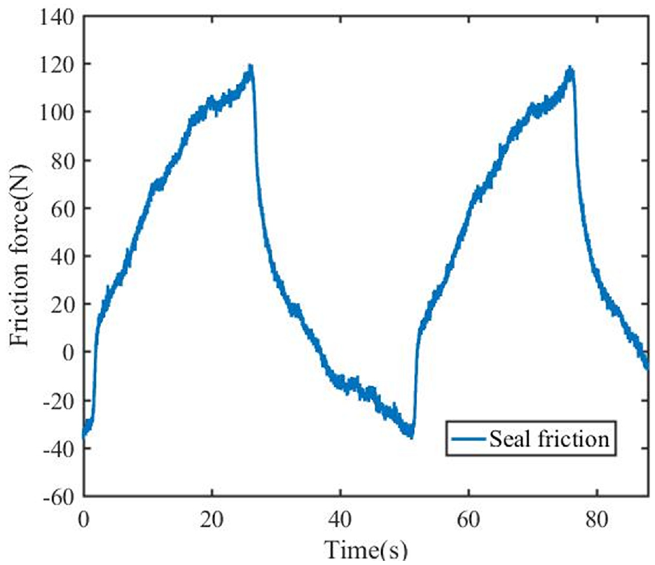
Seal friction force without pre-compression.
The maximum friction forces are 120 and 36 N under different strokes, respectively. The main reasons are the different internal pressure and characteristics of the step seal. The average friction force of the proposed MR damper is 78 N approximately. Comparing with conventional MR damper, the friction force increases significantly. This is caused by the proposed pressure controlled mechanism. The larger internal pressure means more sealing devices and the larger friction force.
4.3. Performance tests and analysis
The performance tests of the proposed MR damper have been carried out with sinusoidal displacement excitations. The excitation frequency changes from 5 to 25 Hz with an increase of 5 Hz. The magnetic field of the proposed MR damper can be controlled by the applied current with a range of 0–2.5 A with a step of 0.5 A. What’s more, the pre-compression should be considered in the performance test with the range of 0–4 MPa with an increase of 1 MPa. The amplitude is 0.1 mm. The dynamic characteristics of the proposed MR damper are further analyzed by the damping force-displacement loop under different excitations and pre-compressions.
4.3.1 Characteristics with different currents
Firstly, the output performance of the proposed squeeze mode MR damper with different currents has been analyzed. When the frequencies are 10 and 20 Hz with the pre-compression of 0 and 2 MPa, the experimental results of damping force-displacement loops are shown in Figures 10 and 11.
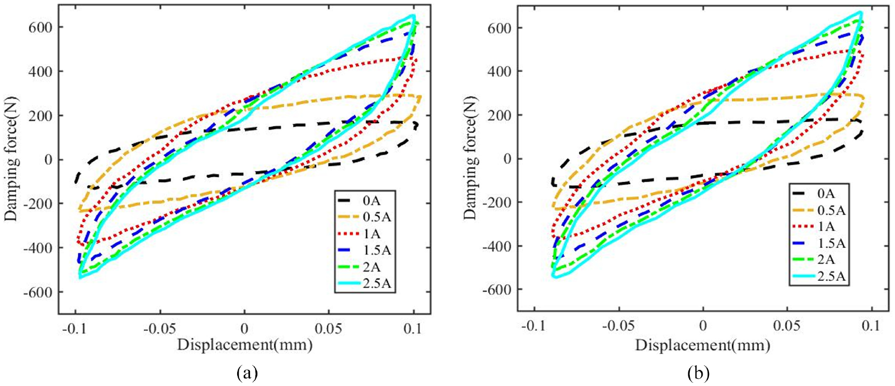
Force-displacement loops with different currents without pre-compression: (a) 10 Hz and (b) 20 Hz.
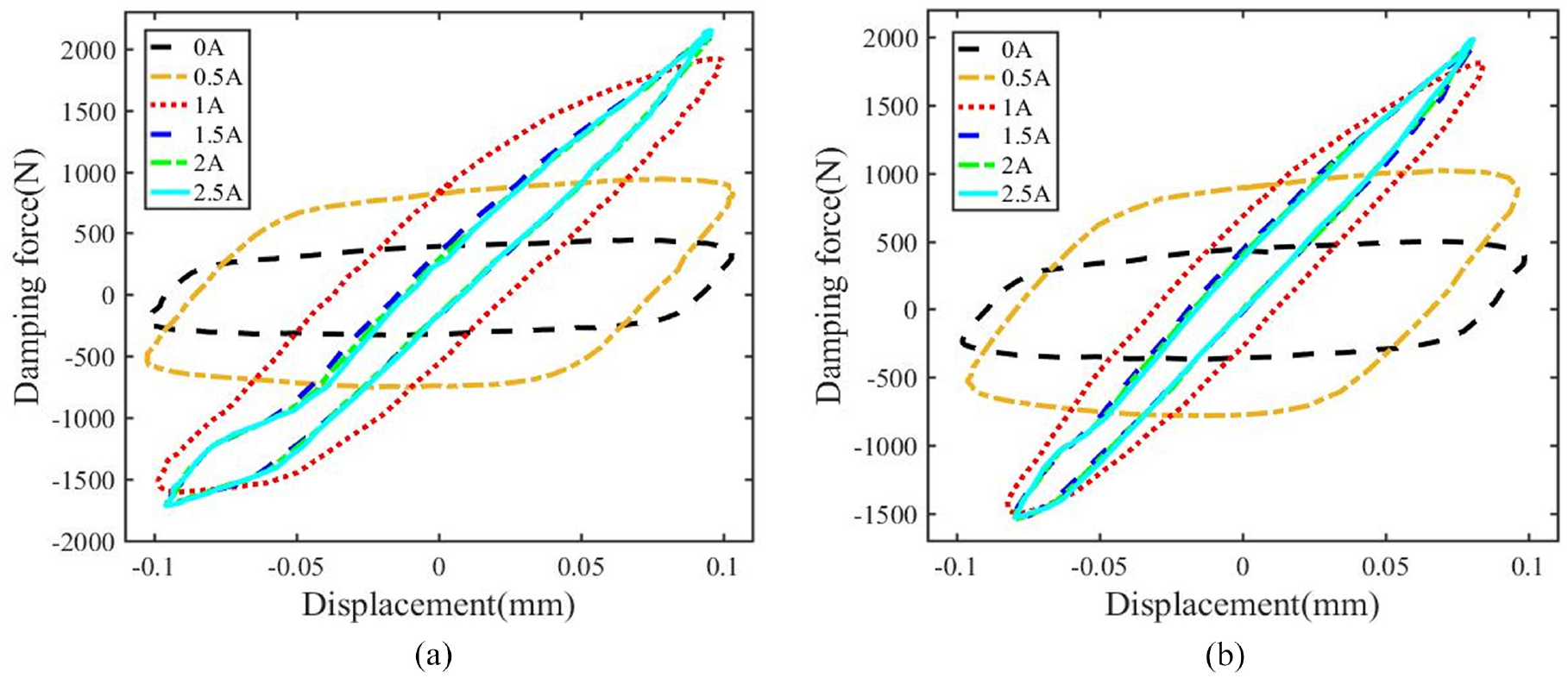
Force-displacement loops with different currents with pre-compression of 2 MPa: (a) 10 Hz and (b) 20 Hz.
As shown in Figure 10(a), the maximum damping force increases with the increase of the current which changes from 141 to 616 N. The main reason is the increase of the controllable magnetic damping force which is directly related to the applied current. However, when the current is larger than 2.0 A, the damping force remains basically invariant because of the magnetic saturation of MR fluid. The adjusting range reaches to 4.3 under this excitation. Comparing with Figure 10(b), with increasing the excitation frequency, the variations of damping force at different currents are almost the same. The maximum damping force remains consistent under different frequencies.
What’s more, the working state of the proposed MR damper has been analyzed. The transition between damping and stiffness properties is determined by the shape of force-displacement loop (Peng et al., 2014). As shown in Figure 10, when the applied current is less than 1 A, MR damper behaves damping property. With the further increase of the current, it shows stiffness property and MR damper works in pre-yield region. Dynamic stiffness increases rapidly which can be obtained by the slope of force-displacement loop. Therefore, the critical boundary between damping and stiffness regions is 1 A. The main reason of this effect is that the stronger particle chains can be formed with the increase of the applied currents.
When the excitation frequency increases to 20 Hz, the critical boundary and output performance is almost the same. It means that performance of the proposed MR damper is not sensitive to the frequency.
Besides these, considering pre-compression caused by the proposed pressure controlled mechanism, the output performance with different pre-compression has been comparatively analyzed. As shown in Figure 11(a), the damping force increases with increasing the current. The maximum force changes with the increases of the applied currents. When the current is larger than 1 A, the damping force remains the same with the increase of the current. The critical current of the force saturation increases with increasing the pre-compression. What’s more, there is an exciting point which should be analyzed in Figure 11. There are two slopes under the same excitations. In Figure 11(a), when the current is 2.5 A, there is a transition point of the dynamic stiffness in the amplitude of 0.05 mm during tension process. The dynamic stiffness increases rapidly when the amplitude is larger than critical value. The reason is the difference of effective regions and total volume with upper and lower gaps. Due to the pressure controlled mechanism, the volume of lower gap is significantly larger than the upper chamber. The effective working region of MR effect in lower gap is smaller than upper gap. When the MR damper works in the compression process, the corresponding dynamic stiffness and damping force are smaller than the values of tension process. In general, the transition point should be located in the initial position. Considering the pre-compression, the transition point moves downward along the axial direction. It can be validated by the experimental results of Figure 11(b). With increasing of the frequency, the force-displacement loop behaves as the single stiffness. The behavior of the transition point can be improved by pre-compression.
Comparing with the conventional squeeze mode MR damper under large amplitude excitation, the sudden change of the damping force will not happen in the conversion between the compression and tension processes under small amplitude and medium-high frequency (Chen et al., 2017; Wang and Gordaninejad, 2007). The output characteristics are obviously different from the conventional squeeze mode MR dampers. The peak compressive force decreases gradually with a specific velocity during tension process. The dynamic stiffness keeps constant under the same excitations. The possible reason is the small amplitude. When the excitation amplitude is small which is less than 0.1 mm, the amplitude is so small that the damping force is large enough. The damping force will increase with a specific slope. According to the force-displacement loop, MR fluid will work in the pre-yield region. Under these excitations, MR fluid behaves the viscoelasticity which generates the increase of the dynamic stiffness.
4.3.2. Characteristics with different frequency
The damping force with different excitation frequencies are comparatively analyzed under small amplitude and medium-high frequency. The experimental results with the applied current of 2 A and the pre-compression of 0 and 2 MPa have been shown in Figure 12. In previous literature, the damping force is frequency-independent with the conventional squeeze mode MR dampers (Chen et al., 2016). In the proposed squeeze mode MR damper with pressure controlled mechanism, when the amplitude is 0.1 mm, the damping force is basically the same with the increase of the frequency without pre-compression. The energy dissipated performance is approximately unchanged. When the pre-compression of 2 MPa is applied to the MR damper, the damping force increases rapidly. With increasing the frequency, the output damping force and the dynamic stiffness are almost the same under different excitations. These behaviors show that the squeeze mode MR damper is not sensitive to the frequency which can be used in applications with high frequency. However, it can be observed that the input displacement is less than 0.1 mm when the frequency is larger than 20 Hz in Figure 12(b). This error is mainly caused by MTS. MTS cannot response in time under medium-high frequency. The actual displacement is slightly less than 0.1 mm. This error cannot be avoided in the experiments.
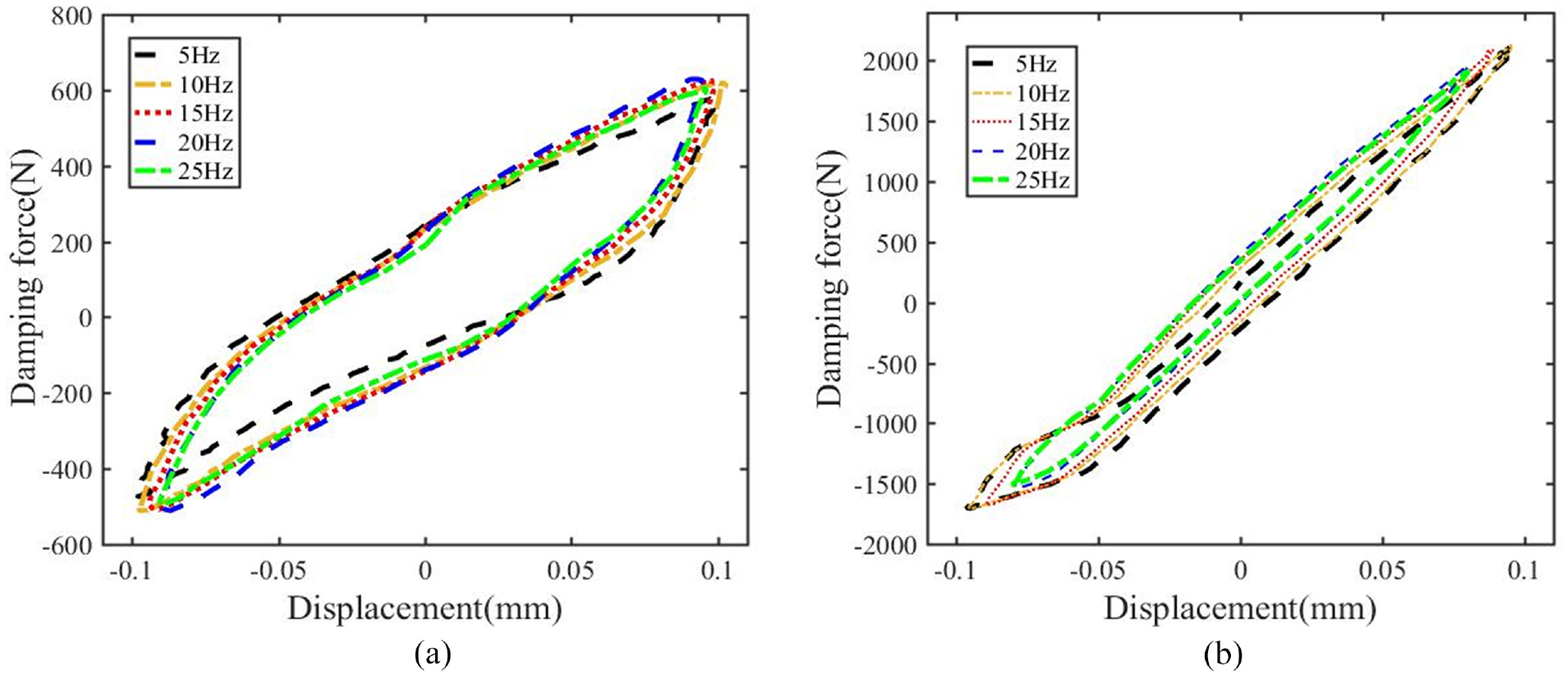
Force-displacement loops with the current of 2 (a) and different frequencies: (a) no pre-compression and (b) pre-compression of 2 MPa.
As shown in Figure 12, the transition point can be clearly observed under the excitations with different frequencies. When pre-compression increases to 2 MPa, the transition point moves to the lower gap with 0.05 mm. With the increase of the frequency, the transition point keeps the constant. What’s more, the working state of MR fluid is still in the pre-yield regions. The experiment results validate that the performance of the squeeze mode MR damper is irrelevant to frequency.
4.3.3. Performance with pre-compression
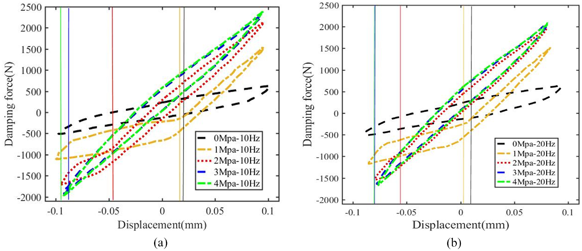
The pre-compression and the high frequency hardening effect have been qualitatively and quantitatively analyzed with the proposed MR damper. Experimental results with different pre-compressions have been shown in Figure 13. When the small amplitude and high frequency are applied into the squeeze mode MR damper, the high frequency hardening effect cannot be avoided. It means that the damping force and energy dissipations will decrease rapidly with increasing the applied current. When the amplitude is less than 0.1 mm, the performance is seriously deteriorated which is the typical high frequency hardening effect. As shown in Figure 13, the damping force increases sharply with increasing the pre-compression. The maximum damping force is 1916 N with the frequency of 20 Hz and current of 1.0 A. It increases by 321.6% compared with the initial value. So the maximum damping force can be dramatically improved by pre-compression. What’s more, the energy dissipations have been improved by pre-compression. At off-state of the MR damper, the energy dissipation has been increased by 252.3%. When the high frequency of 20 Hz is applied in Figure 13(d), comparing with the condition of low frequency, the improvement for the high frequency hardening effect decreases which only reaches to 107.6%. It means that the high frequency has a negative impact with the improvement caused by pre-compression. The possible reason is that the enhanced magnetic particle chain is more sensitive to the frequency (Christian and Jurgen, 2016). The squeeze strengthening effect by the pressure controlled mechanism will decrease with increasing the frequency.
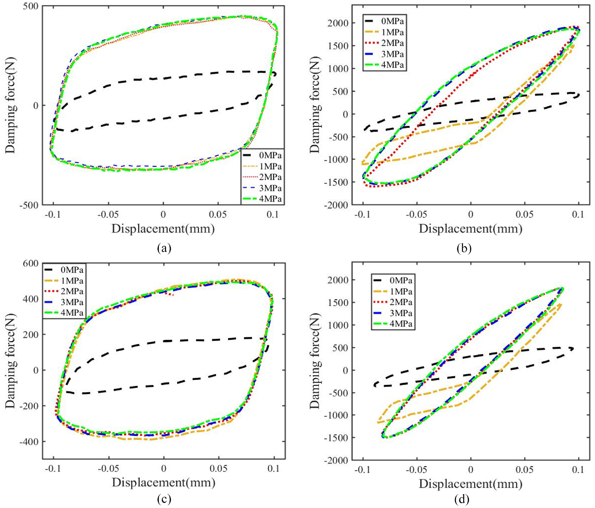
Damping force-displacement loops with pre-compressions: (a) 10 Hz & 0 A, (b) 10 Hz & 1 A, (c) 20 Hz & 0 A, and (d) 20 Hz & 1 A.
When the pre-compression is larger than the critical value of 1 MPa, there is no improvement with output performance. The damping force and energy dissipation keep stable approximately. The first reason is that the enhanced particle chains have been formed under a lower pre-compression. The optimized yield stress has been reached. The second reason is that MR fluid has been compressed and it will flow through the working gap.
Meanwhile, the transition between damping and stiffness properties under this condition has been analyzed. Under the excitation of the lower current, MR damper behaves damping property obviously with increasing the pre-compression. MR damper works in post-yield region and the energy dissipation increases rapidly. When the applied current is larger than 1 A, MR damper behaves stiffness property and the corresponding dynamic stiffness increases significantly with the increase of the pre-compression. The main reason of this effect is that the complicated particle chains will be formed and strengthened by pre-compression. Under lower current, the improved strength cannot meet the critical strength between damping and stiffness regions. When the applied current becomes higher, the reinforced particle chains can improve damping force and dynamic stiffness effectively. Therefore, the working state of the proposed MR damper is closely related to pre-compression.
What’s more, the transition point moves with different pre-compressions. As shown in Figure 14, pre-compression has a significant effect on the transition point. With the increase of the pre-compression, the transition point moves downward along the axial direction. This phenomenon is mainly determined by the enhanced particle chain and direction of magnetic field. When the pre-compression is applied into MR damper, the particle chains in all regions have been enhanced. The dynamic stiffness of region 2 is equal to region 1 approximately. What’s more, due to the inclination of magnetic field, the strength of particle chains in region 4 is smaller than other regions. The corresponding stiffness and damping force is smaller other regions. In the initial stage of compression process, damping force is provided by particle chains in region 2. However, the effective region of region 2 is smaller than region 1. It is easy to be broken. Therefore, in the later stage of compression process, the performance is related to the property of region 4. The damping force and stiffness have a sudden change. This sudden change is the proposed transition point. With increasing the pre-compression, the strength of region 2 increases rapidly. It means that the larger force is needed to destroy the particle chains. The corresponding transition point moves downward gradually with the increase of pre-compression.
Transition point with different pre-compressions under current of 2.0 A: (a) frequency of 10 Hz, and (b) frequency of 20 Hz.
When the pre-compression is large enough, the dynamic characteristics behave as the single stiffness. Under the frequency of 20 Hz and current of 2.0 A, the stiffness keeps constant when pre-compression is larger than 2 MPa. The main reasons are the magnetic saturation and the enhanced structure of magnetic particle chains by the high frequency hardening effect. With increasing the pre-compression, the yield stress will increase and the pre-yield region can be enlarged. The stiffness of MR fluid increases too. The stiffness of the proposed MR damper under the tension is improved. For example, under the frequency of 5 Hz and current of 1.0 A, the stiffness of the proposed MR damper increases to 20.75 kN/mm.
4.3.4. Analysis of energy dissipation
In order to further analyze the high frequency hardening effect, the energy dissipated per cycle E has been used to validate the improvement. The energy dissipation is the area enclosed in the force-displacement loop (Abdalaziz et al., 2022). It can be shown as
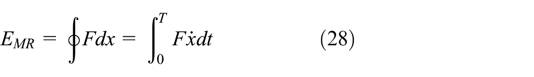
Where F is the damping force. x is the displacement. T is the excitation period.
The energy dissipation with the applied current of 0.5 A is shown in Figure 15. The output performance is frequency-independent. So the frequency is not analyzed in this section. When the pre-compression is 1 MPa, the maximum energy dissipation is 0.1712 N.m which is increased by 342% compared with the initial value. It means that the isolating performance of the proposed MR damper has been improved significantly by the squeeze strengthening effect. And the energy dissipation increases with the increase of pre-compression. Therefore, the high frequency hardening effect of the squeeze mode MR damper can be effectively improved by pre-compression.
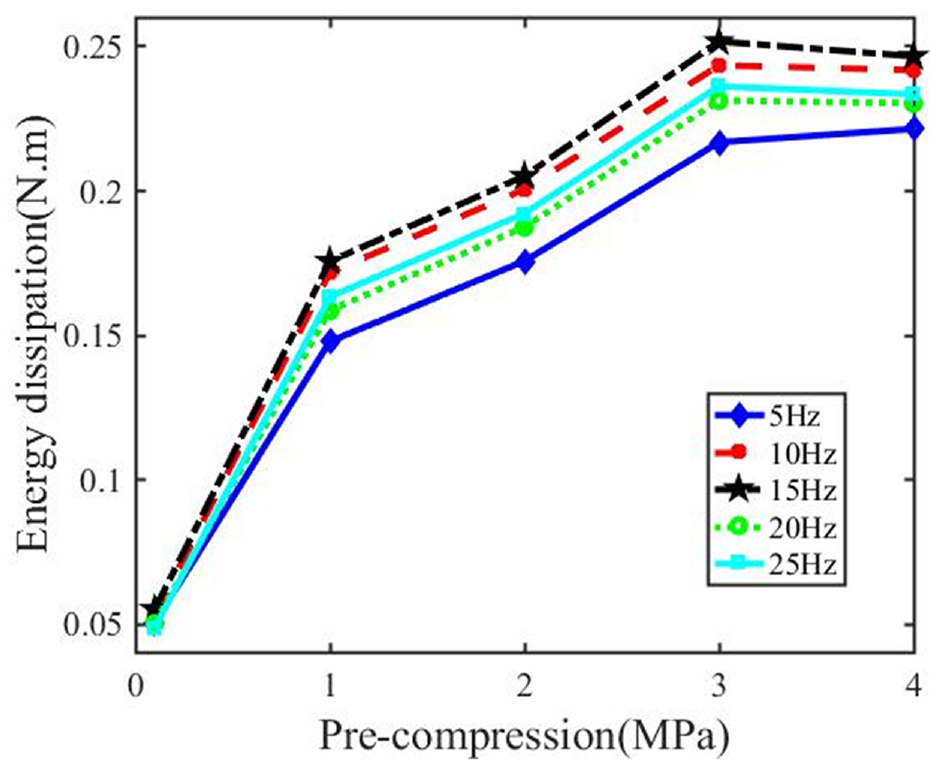
Energy dissipation of the proposed MR damper under different pre-compressions.
Besides these, comparisons between the theoretical and experimental results are analyzed to validate the correctness of the proposed theoretical models. Under the frequency of 10 and 20 Hz, comparisons are shown in Figure 16.
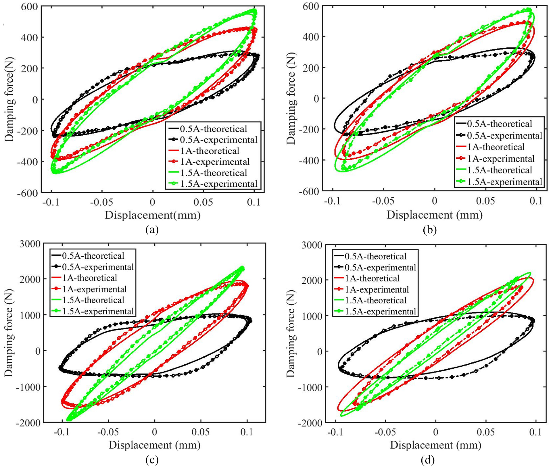
Comparisons between theoretical and experimental results under different excitations: (a) 0 MPa & 10 Hz, (b) 0 MPa & 20 Hz, (c) 4 MPa & 10 Hz, and (d) 4 MPa & 20 Hz.
It can be observed that the theoretical results are in good agreement with the experimental results. The disagreement appears at high frequency of 20 Hz. The maximum error with damping force is 11.6% at the current of 1.5 A and pre-compression of 4 MPa. The main reason is the limitation of MTS. Under this excitations, MR fluid works in pre-yield region and will not flow in the gap. The stiffness increases and MTS cannot response in time. The input displacement and damping force is lower than theoretical results. What’s more, the minor loss and compressibility of MR fluid are ignored in theoretical models. What’s more, the change of slope in the theoretical model is produced by the difference of stiffness and damping properties between upper and lower gaps. Due to the difference of effective regions and total volume between two gaps, there is a transition state of damping force in the modeling results.
What’s more, all errors under other excitations are within a reasonable range. It means that theoretical model can accurately predict and describe the output performance of the proposed squeeze mode MR damper under small amplitude and medium-high frequency.
5. Conclusion
In this paper, mechanical properties of the proposed squeeze mode MR damper have been quantitatively and qualitatively analyzed and evaluated under small amplitude and medium-high frequency. In order to improve the high frequency hardening effect, a novel squeeze mode MR damper with the pressure controlled mechanism has been proposed, manufactured and tested. The initial pressure of MR fluid can be adjusted by pre-compression. To further analyze the mechanical performance under such excitations, considering the pre-compression, distribution of post-yield regions, inertia and viscoelasticity of MR fluid, a novel physical model has been developed based on the continuum media theory. Comparing with the general properties of typical squeeze mode MR damper, experimental results demonstrate that the peak compressive force will not suddenly jump to the tensile force in the transition between compression and tension processes under such excitations. The damping force changes gradually with a specific slope which shows the stiffness property obviously. A transition point between two different stiffness is generated which is caused by the difference with effective working regions of two gaps. The transition point moves downward with increasing the pre-compression. What’s more, the squeeze strengthening effect of squeeze mode MR damper has been validated and analyzed. The high frequency hardening effect of the proposed MR damper can be significantly improved by pre-compression under such excitations. The damping force increases by 321.6% with pre-compression of 2 MPa. The maximum energy dissipation is 0.1712 N.m which is increased by 342% with pre-compression of 1 MPa. Besides these, theoretical model is in good agreement with the experimental results. Therefore, the proposed squeeze mode MR damper has a good performance under small amplitude and medium-high frequency. The high frequency hardening effect can be improved by pre-compression effectively. It can be widely used in precision isolating system or other critical applications.
Footnotes
Declaration of conflicting interests
The authors declared no potential conflicts of interest with respect to the research, authorship, and/or publication of this article.
Funding
The authors disclosed receipt of the following financial support for the research, authorship, and/or publication of this article: This research was financially supported by National Natural Science Foundation of China (No. 52075056), and additionally supported by Graduate Research and Innovation Foundation of Chongqing, China (CYB21012).