
Abstract
In order to meet the damper performance requirements of heavy vehicles, a stepped-bypass magnetorheological damper is proposed. The mathematical model of damping force is deduced, and its mechanical properties are numerically simulated. Then the damper is manufactured, and the mechanical properties of the stepped bypass magnetorheological damper are experimentally studied. The simulation are consistent with the experimental results. The damper is optimized by orthogonal optimization design test. Finally, it is concluded that the maximum output damping force of the stepped bypass magnetorheological damper is about 4500 N, and the adjustable coefficient K is about 5.4. After optimization, the damping force of the stepped bypass magnetorheological damper is increased by at least 5.3%, and the adjustable coefficient K is at least 1.37 times that before optimization, which is 13% wider than that before optimization.
1. Introduction
Magnetorheological fluid is a fluid that changes in response to a change in a magnetic field and can transform from a Newtonian fluid to a visco plastic body in millisecond time and reversible. Due to the very good application of magnetorheological effect, it is widely used in anti-vibration fields such as vehicles, ships, and building structures. Magnetorheological damper is a semi-active control system made of magnetorheological fluid, which combines the advantages of simple passive control structure, high reliability and good active vibration reduction effect. At present, the damper has high requirements on the damping performance in the use of heavy vehicles, which brings new challenges to the structural design of the damper.
At present, there are many studies on the structural design of magnetorheological dampers (Liu et al., 2021b) and others proposed a magnetorheological damper with multiple slots on the piston, and for the first time verified the superiority of the magnetorheological damper with multiple slots on the piston. In order to improve the adaptability of the damper in the vibration system environment. Jiang et al. (2022b) designed a new type of magnetorheological damper with selectable performance parameters. The damper can automatically switch the working channel according to the actual stroke, thereby improving the response of the vibration system to unexpectedly increased loads. Olivier and Sohn (2021) proposed a hybrid magnetorheological damper, which can improve the ride comfort and road holding ability of the car under bumpy and random road conditions. In order to obtain a larger damping force under the limited axial size of the vehicle suspension system. Liu et al. (2022a) developed a new type of series flow channel magnetorheological damper, which experiments show that the new series magnetorheological damper has high vibration control ability and good mechanical properties. In order to improve the damping performance of the magnetorheological damper, added magnetically permeable and non-magnetically permeable materials to its structure to make the magnetic lines of force meander, and tested its damping characteristics (Cheng et al., 2018). The results show that the magnetorheological damper with meandering magnetic circuit can improve the efficiency of the magnetorheological damper. Proposed and manufactured a magnetorheological damper with double-baffle valve as an internal bypass, established a theoretical model of finite element analysis, and verified its characteristics experimentally. As a comparison, a magnetorheological damper with an annular valve installed in the piston damper, which is constrained by the same external volume as the double-baffle valve damper, is also analyzed to illustrate the improved performance of the double-baffle valve damper (Wang et al., 2019). In order to optimize the working performance of the magnetorheological damper, designed a new parallel-gap magnetorheological damper. By establishing the mathematical model of the parallel gap magnetorheological damper, the correctness of the structural design is verified and guided (Dong et al., 2019; Kim et al., 2020). Proposed a novel magnetorheological damper that can achieve the desired damping force at both high and low vehicle speeds. The proposed damper has a specific pole shape function, and the damping coefficient is changed by changing the effective area of the main hole, and the mathematical modeling of the pole shape function is carried out, and the feasibility of the new magnetorheological damper is verified by example. At present, many people have carried out a lot of optimization work on the structure of the magnetorheological damper, in order to improve the structure and related performance of the damper (Deng et al., 2022a; Hu et al., 2021; Huina et al., 2021; Nanthakumar and Jancirani, 2019). In order to improve the damper-related performance of the magnetorheological damper in a limited structure, some scholars have studied the application of metal foam in the magnetorheological damper (Yao and Pecht, 2020; Yao and Peng, 2018). Proposed a magnetorheological damper along an annular radial channel, designed its structure and magnetic circuit, and verified the rationality by experiments. The results show that the damping force of the damper increases obviously and the adjustable range is wide (Zhu et al., 2016). A foreign author proposed an adaptive optimal control method based on policy iteration for constrained semi-active vehicle suspension system with magnetorheological damper. Wang (2018) proposed a suspension composed of a pneumatic system that can change the suspension stiffness and a semi-active magnetorheological damper that can control the suspension damping. It is concluded that the proposed Mr/pneumatic suspension achieves the same roll Angle level as similar passive vehicles, while improving ride comfort by reducing acceleration by up to 30% (Morales et al., 2018). In order to improve the riding comfort and operating stability of the driver, carried out the overall vibration attenuation experiment on the off-road vehicle equipped with magnetorheological damper. It was proved that, compared with the passive suspension, the properly adjusted Skyhook algorithm could improve the vehicle handling (Krauze et al., 2019). Many researchers have applied magnetorheological damper to seat suspension, and studies show that it can significantly improve the vibration control performance of seat suspension (Deng et al., 2022b; Zuo et al., 2021). There are studies on large magnetorheological dampers for applications in civil and structural engineering, etc. The results show that the performance of large magnetorheological dampers is adequate (Abdul Aziz et al., 2022). In addition, magnetorheological dampers can also be used in the field of aerospace for lunar landers and in the field of aviation for helicopters, and the final experimental results can be concluded that magnetorheological dampers have good applications in various fields (Luong et al., 2021; Wang et al., 2021). In the structural design of magnetorheological dampers, the advantages of bypassed magnetorheological dampers are higher shear stress, good damping force adjustability and the possibility of higher maximum damping force generated (Aziz and Aminossadati, 2021). For the design of magnetorheological damper coils, some researchers study the magnetorheological damper with three coils and propose a mathematical model applicable to the magnetorheological damper with three coils, which provides information for the design and analysis of future magnetorheological dampers with multiple coils (Yang et al., 2021). For the optimization of magnetorheological dampers, the researchers used multi-objective optimization design to optimize the structure and used the most reasonable parameters in each parameter to improve the performance of the magnetorheological dampers (Huina et al., 2021; Jiang et al., 2022a). There are also researchers who have designed and optimized a new MR damper based on B-spline curve and designed and produced a damper that is better in all aspects than the prototype from previous work (Liu et al., 2021b). Additional researchers used Taguchi’s orthogonal experimental method to optimize the structure of the magnetorheological valve and determine the optimal geometry of the magnetorheological valve to maximize the valve performance (Hu et al., 2022). In order to solve the problem of conflicting output damping force and damping adjustable coefficient after the magnetorheological damper is subjected to impact load in the launcher, a new three-channel magnetorheological damper structure is proposed, and the study shows that it can make full use of the multi-channel and multi-coil structure of the magnetorheological damper and improve the damping performance of the magnetorheological damper (Zhu and Zhang, 2022). On the study of control algorithms on damper performance, some researchers found that the performance of magnetorheological dampers is highly dependent on the control algorithm, objective function and damper distribution; also to solve the modeling problem caused by the complex nonlinear hysteresis of magnetorheological dampers, a gray hysteresis model was developed, and it was shown that the average relative error of this model is within a manageable range. In addition, a control strategy using a novel conditional function was proposed, and it was experimentally shown that the desired performance can be achieved, which has great potential in terms of control strategies (Bagherkhani and Mohebbi, 2022; Deng et al., 2022c; Nagamatsu and Shiraishi, 2022). For better control of magnetorheological dampers for air suspension, a fuzzy sliding mode control strategy is proposed, and the simulation analysis structure shows that this strategy has a great improvement in performance for semi-active air suspension (Li et al., 2021a). The main reason for the hysteresis characteristics of magnetorheological dampers is the compressibility of MR fluid. In order to optimize the hysteresis characteristics of magnetorheological dampers, we propose to optimize the structure of magnetorheological dampers using an improved Bingham model, and the results show that the damping performance of magnetorheological dampers can be effectively improved (Wei et al., 2021). Innovative structures are proposed to better improve the performance of magnetorheological dampers. A new MR damper with folded resistive gap and bent magnetic circuit is designed with a multi-stage folded ring intermittent structure, and the results show that the damping force and dynamic range are improved by 55.82% and 62.21%, respectively, compared with the conventional MR damper (Liu et al., 2022b). A new magnetorheological dampener incorporates aluminum foil bubble insulation in the cavity in order to avoid the increase of the magnetorheological fluid temperature. The results show that the temperature in the working area is significantly reduced while the damping force is greatly increased (Du et al., 2021). A new magnetorheological damper using an iron-cobalt-vanadium “Vacoflux-50” alloy and an “AMT-Smart ec+” MR fluid was used to comparatively model the performance of magnetorheological dampers with different magnetorheological fluids. A significant increase in magnetic field and fluid yield stress was found (Elsaady et al., 2020). In order to solve the disadvantages of complex coil structure and high manufacturing cost of most magnetorheological dampers, magnetorheological dampers with simple structure and new magnetic circuit with separate positioning of the piston head were designed. It was derived that a much higher range of controllable damping force than the conventional one can be provided at low damping force level (Lee et al., 2021). Based on the idea of using a large gap at high speed and a small gap at low speed, a new MR damper based on axial variable damping gap (MRD-VDG) was proposed, and a prototype damper was designed and fabricated to verify the effectiveness of the damper design (Xi et al., 2021).
At present, the most important thing is to improve the damping performance of the magnetorheological damper by improving the structure. Most of them focus on increasing the length of the damping channel and increasing the utilization rate of the magnetic field. And there are also a few reasonable non-magnetic conductive materials, so as to achieve the purpose of increasing the output damping force of the magnetorheological damper. However there is still the problem that the damping force is not large enough to meet the application of the magnetorheological damper on heavy vehicles.
A new type of stepped bypass magnetorheological damper is proposed in this paper. The damper adopts the structure of a double-rod hydraulic cylinder and a stepped bypass valve that plays the role of damping adjustment, and the flow channel is composed of a stepped channel. In this way, the effective action area of the magnetorheological fluid can be increased without increasing the size of the damper, thereby effectively increasing the output damping force and the adjustable coefficient. At the same time, mathematical model establishment and electromagnetic field simulation analysis are carried out. Finally, the orthogonal test is carried out on the structural parameters, and the relevant optimization analysis is done to verify the rationality of the damper design.
2. Structural design and magnetic circuit design
2.1 Selection of magnetorheological fluid
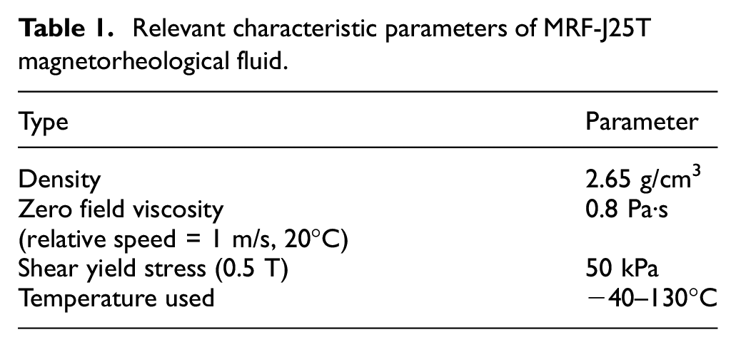
The magnetorheological fluid selected in this paper is the MRF-J25T type developed by Chongqing Instrument Materials Research Institute. Table 1 shows the relevant characteristic parameters of the MRF-J25T magnetorheological fluid. Figure 1 shows the relationship between shear yield strength
Relevant characteristic parameters of MRF-J25T magnetorheological fluid.
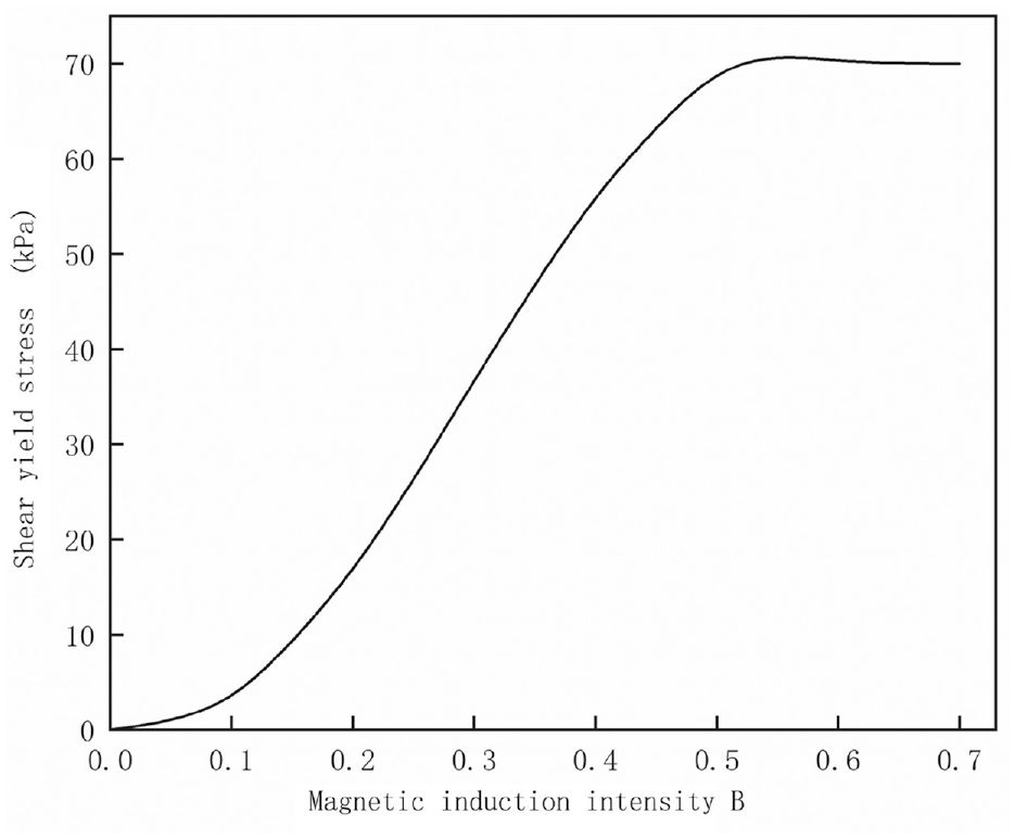
τ − B curve of MR fluid.
2.2 Design of structural parameters
The stepped bypass magnetorheological damper is mainly composed of two parts. One is the main hydraulic cylinder of the damper, which adopts a double-rod structure type, and the other is a stepped bypass valve that plays the role of damping adjustment the, structure diagram of stepped bypass magnetorheological damper is shown in Figure 2.
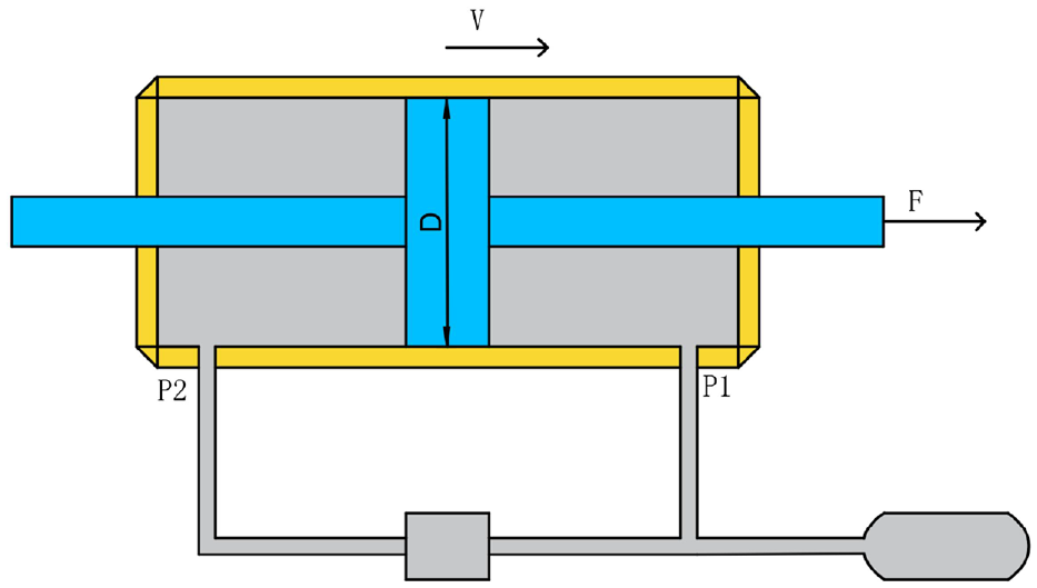
Structure diagram of stepped bypass magnetorheological damper.
In order to make the performance of the magnetorheological damper meet the use on heavy vehicles, the designed stepped bypass magnetorheological damper has a maximum damping force of 3000 N and an adjustable coefficient K of 4, and the adjustable coefficient K is the ratio of the Coulomb force generated by the magnetorheological fluid in the presence of a magnetic field to the viscous force in the absence of a magnetic field. The piston rod is the main force-bearing component of the damper, which is convenient for comprehensive processing. The size parameters of the hydraulic cylinder are selected in the following Table 2.
Related parameters of hydraulic cylinder.

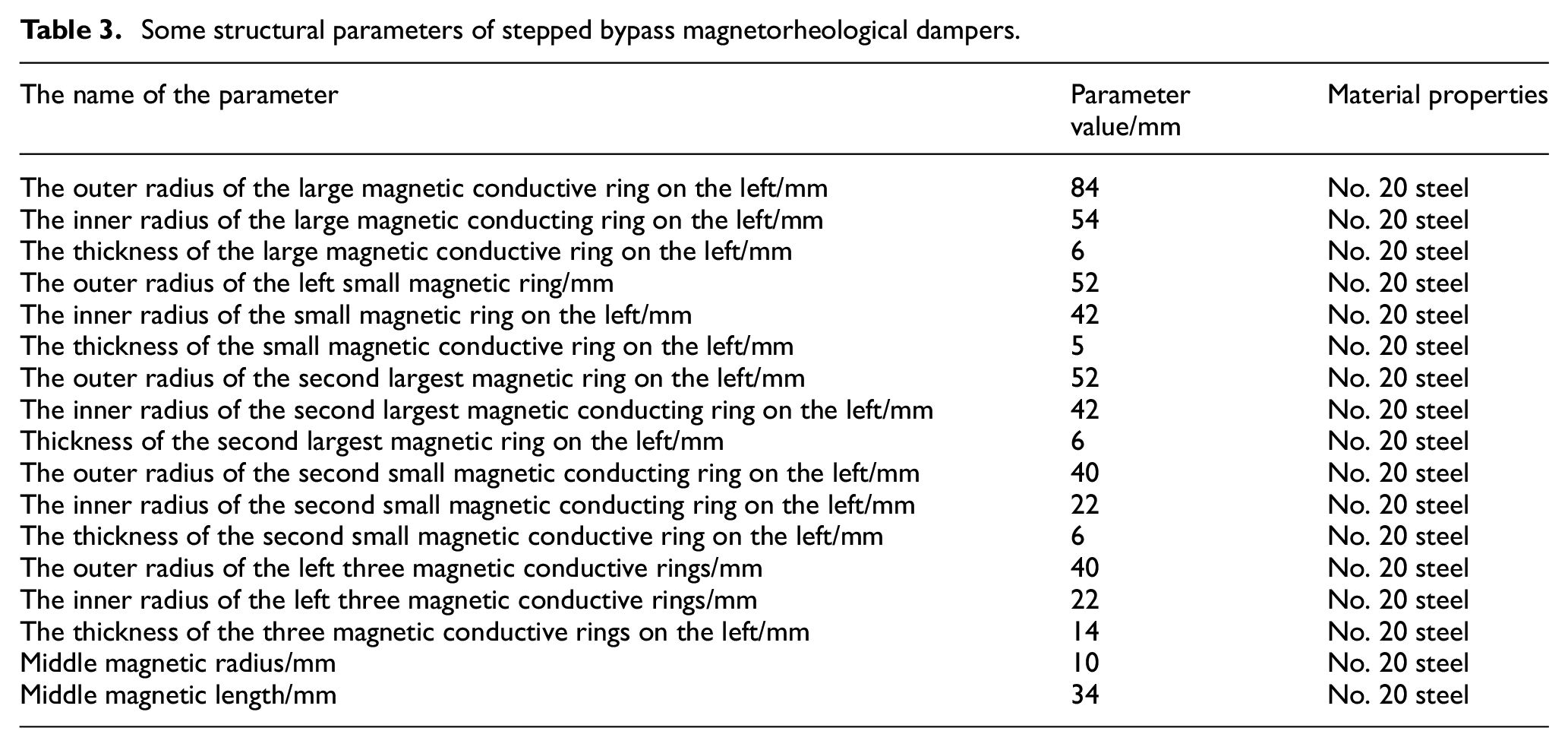
In order to make the damper output larger damping force and wider adjustment range under the same volume. After proper adjustment of some damper structure data, the relevant structural parameters are shown in Table 3, the Structure diagram of stepped bypass magnetorheological damper is shown in Figure 2, and a nitrogen-loaded oscillator has been added to the structure to supplement the rebound process of the double rod hydraulic cylinder. The two-dimensional structure diagram of the bypass valve is shown in Figure 3.
Some structural parameters of stepped bypass magnetorheological dampers.
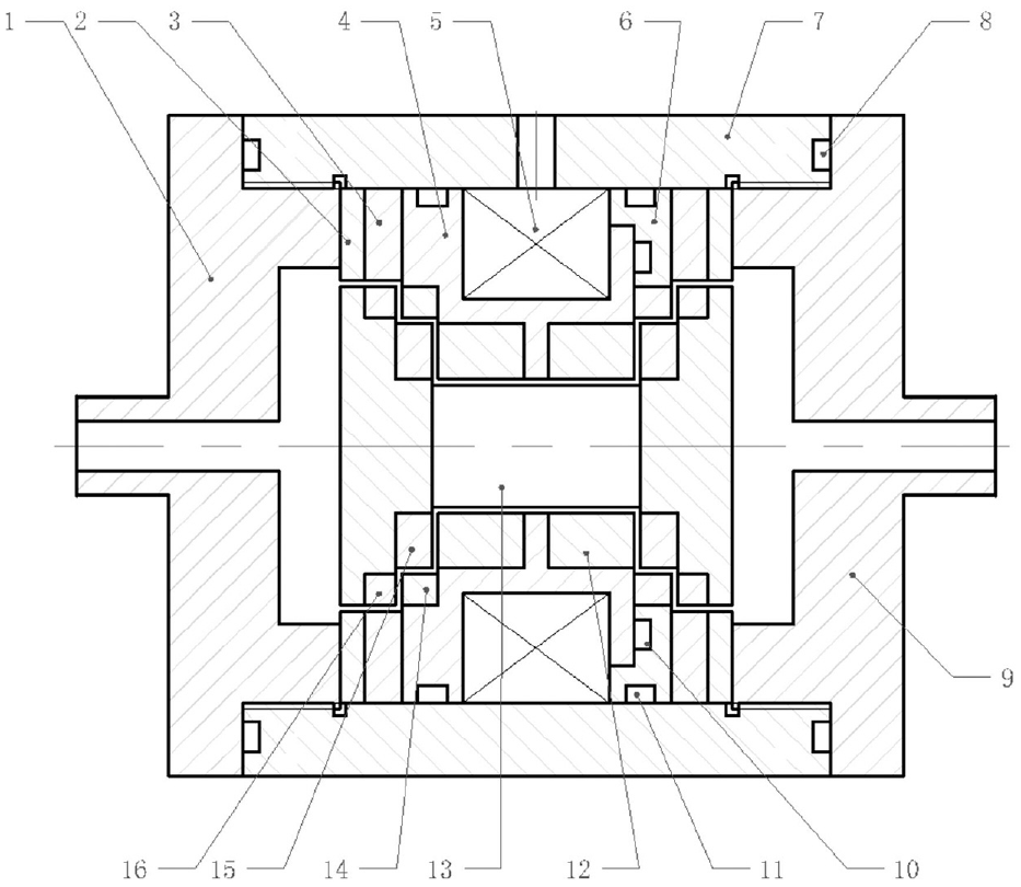
Schematic diagram of the two-dimensional structure of the bypass valve 1—left end cover, 2—positioning plate, 3—left large magnetic conducting ring, 4—left coil bracket, 5—excitation coil, 6—right coil cover, 7—shell, 8—O-ring, 9—right end cover, 10—O-ring, 11—O-ring, 12—right three magnetic conducting rings, 13—the middle magnetic conductive ring, 14—the second large magnetic conductive ring on the left, 15—the second small magnetic conductive ring on the left, and 16—the small magnetic conductive ring on the left.
The execution standard of No. 20 steel is: GB/T711-2017. and its yield strength is 245 Mpa, modulus of elasticity is 206 Gpa, Poisson’s ratio is 0.3, shear strength is 275–392 MPa, tensile strength is 253–500 MPa, yield strength is 275 MPa and elongation is 25%.
2.3 Magnetic circuit design
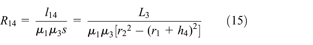
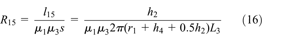
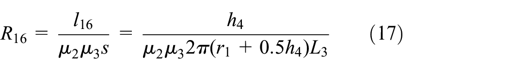
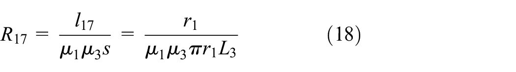
The schematic diagram of the magnetic circuit of the bypass valve is shown in Figure 4. Due to the symmetry of the structure, half of the structure is taken for research, corresponding to a total of 18 magneto resistances. The size of the bypass valve is shown in Figure 5.
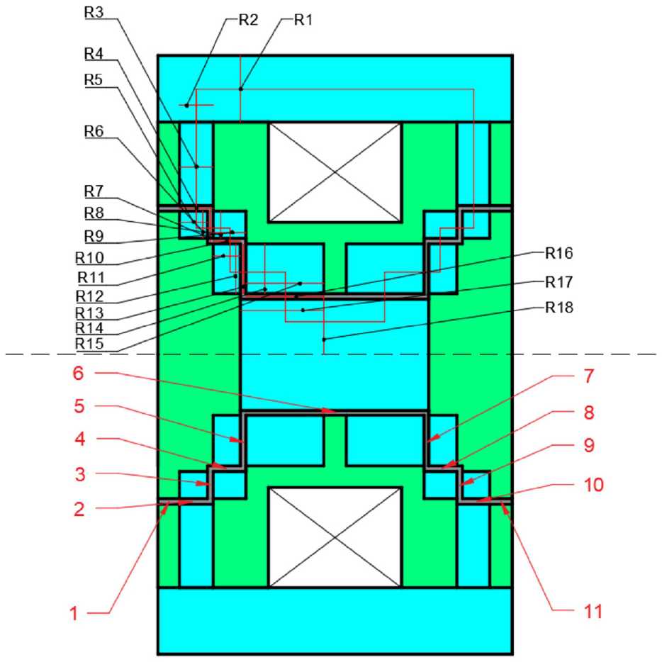
Magnetic circuit schematic and flow channel diagram.
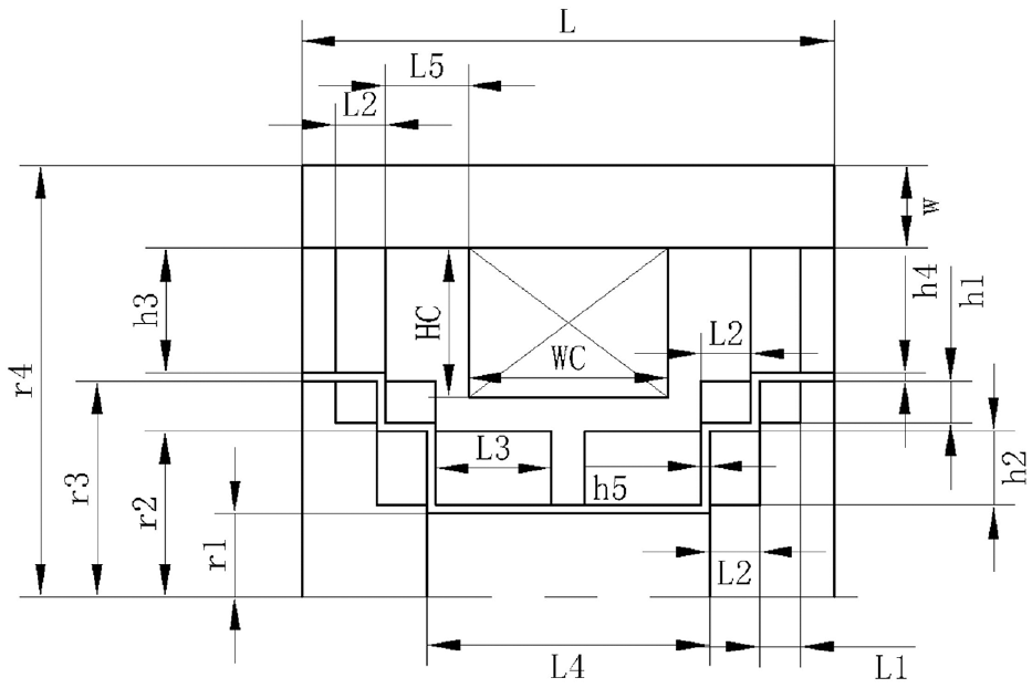
Dimensions of the bypass valve.
The shell and the magnetic conductive material are made of 20# steel, which has good magnetic permeability, and its magnetic permeability is
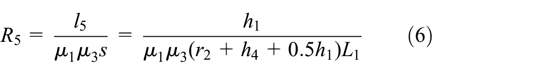
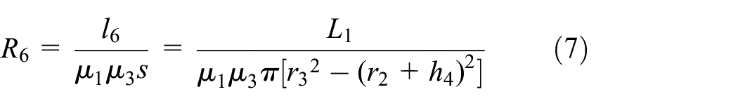
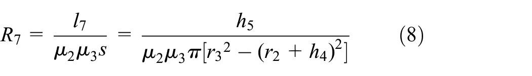
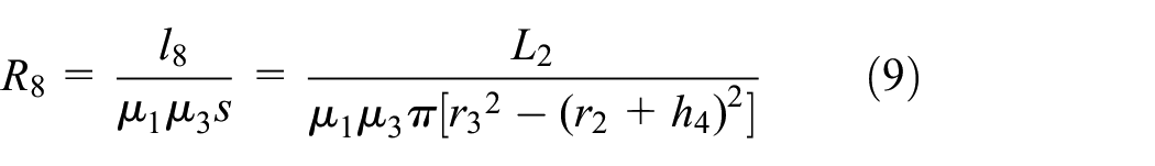
The formula for calculating the magneto resistance R is Zhao et al. (2020)
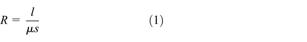
Where l is the length that the magnetic field line passes vertically, s is the cross-sectional area that the magnetic field line passes vertically.
Combining the magneto resistance and dimensional structure parameters marked in Figures 4 and 5, the corresponding magneto resistance formula for each part is derived by taking the magneto resistance formula (1) as follows:
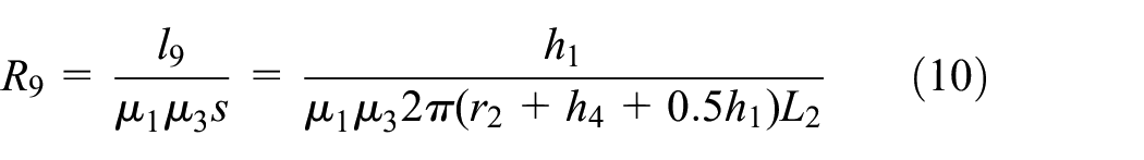
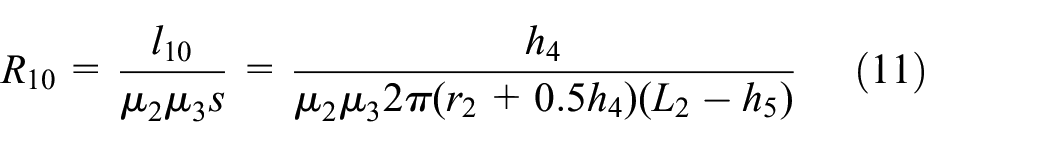

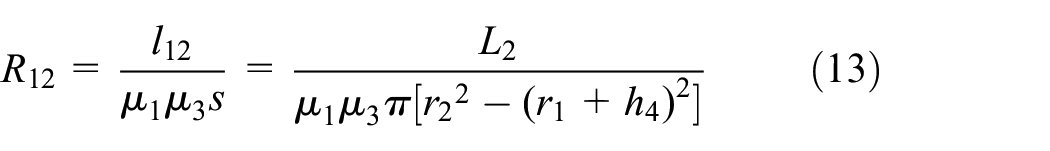
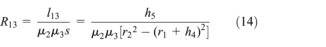
The total reluctance in the magnetic field loop is:
According to Ohm’s law for magnetic circuits: Zhao et al. (2020)
Where,
So, calculate the required magneto motive force:

The copper wire with a diameter of 1 mm is selected in the design. Assuming that the magnetic flux reaches saturation at a current of 4 A, the required number of coil turns N is about 275 turns, The size of the cross section of the coil slot is 24 mm × 18 mm = 432mm2. It can be calculated that the number of coil turns that can be wound around the coil slot is 432 turns.
2.4 Mathematical model of output damping force
From Newton’s second law it can be concluded that:

Where F is the external force on the piston rod, M is the mass of the piston rod and the piston head.
A represents the effective piston area, and it is expressed as: Wang et al. (2019).

Where
Therefore:

During the experiment, the piston rod starts to move under the external excitation, but the change of speed is relatively slow, so the acceleration is small, and its mass is not large, so it can be ignored.

According to the mechanical model, the pressure drop calculation methods of different channels are also different, so the damping channel of the damper is divided into 11 parts. The flow channel is shown in Figure 4.
As can be seen from the figure, a viscous pressure drop occurs in each region. Therefore, the formula for calculating the pressure drop of the damper is: Wang et al. (2019).
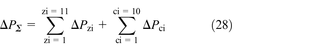
Where
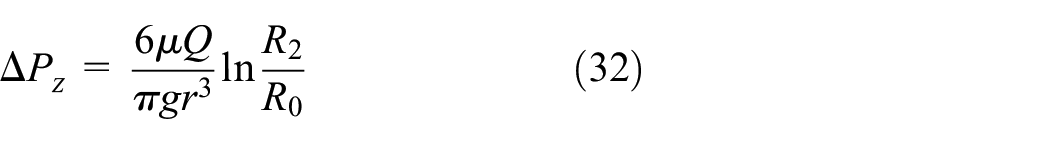
When the liquid flow channel is a cylindrical flow channel, its pressure drop performance is mainly related to its length and radius. So the viscous pressure drop is: Wang et al. (2019).
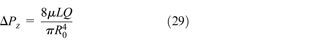
Where L is the length of the circular tube, Q is the flow rate through the circular tube,
When the liquid flow channel is an annular flow channel, its pressure drop performance is related to the gap, length and radius. The viscous pressure drop of the ring is: Wang et al. (2019).
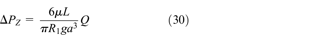
Where L is the length of the ring, Q is the flow rate through the ring,
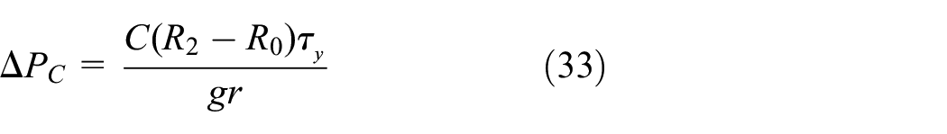
The magneto-induced pressure drop of the ring is: Wang et al. (2019)
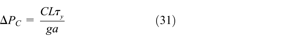
Where C is a constant whose value is 2–3, the formula to take C = 2. L is the length of the ring,
When the liquid flow channel is a disc flow channel, its pressure drop performance is related to the gap and radius.
The viscous pressure drop of the disc is: Wang et al. (2019)
Where Q is the flow through the ring,
The magneto-induced pressure drop of the disc is: Wang et al. (2019)
Where C is a constant with a value of 2–3, the formula to take C = 2.
3. Modeling and simulation analysis
3.1 Modeling of the bypass valve
In this paper, the APDL electromagnetics simulation of ANSYS software is used to simulate the bypass valve part of the magnetorheological damper. The bypass valve is an axisymmetric structure, so one-half of the structure is taken to establish a simplified model diagram, and the final material properties are shown in Figure 6. After the output processing of the calculation results, the distribution map of magnetic force lines as shown in Figure 7. In the Figure 6, A1 is the magnetic conductive material such as the shell, the magnetic conductive ring and the magnetic conductive material in the middle, and the material is 20# low carbon steel; A2 is the coil, choose an enameled copper wire with a diameter of 1 mm, and the relative permeability is 1; A3 is the non-magnetically conductive material such as coil bracket and positioning disc. The material is 304 stainless steel, and the relative magnetic permeability is 0.1.
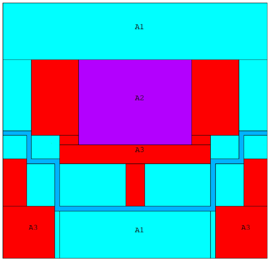
Schematic diagram of material properties.
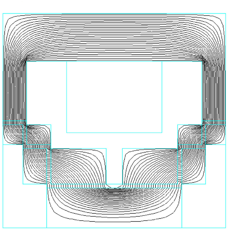
Distribution of magnetic field lines.
It can be seen from Figure 7 that all the magnetic lines of force are basically perpendicular to the effective damping gaps of all the liquid flow channels, and only a small amount of magnetic flux leakage occurs at the corners, which achieves the design goal. The simulation results in Figure 7 yield the magnetic induction intensity B in the damping gap, which can be brought into the relevant equations in Chapter 2 to find the flux and hysteresis pressure drop, and finally to find the final damping force
3.2 Analysis of simulation results
3.2.1 Effect of step type and normal type on damping performance under different current conditions
As can be seen from Figure 8, the damping force of both the stepped structure and the ordinary structure increases with the increase of current. When the current reaches 5 A, the damping force of the stepped structure is 5314 N and the damping force of the ordinary structure is 2299 N, so the damping force of the stepped structure is about 2.3 times of the ordinary structure.
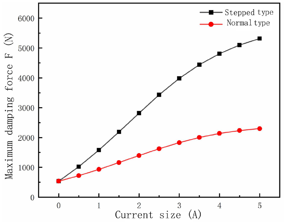
Comparison of damping force between stepped type and ordinary type at different currents.
As can be seen from Figure 9, the adjustable coefficients of both the stepped structure and the ordinary structure increase with the increase of current. When the current reaches 5 A, the adjustable coefficient of the stepped structure is 8.8 and the adjustable coefficient of the ordinary structure is 3.2, so the adjustable coefficient of the stepped structure is 2.75 times of the ordinary one.
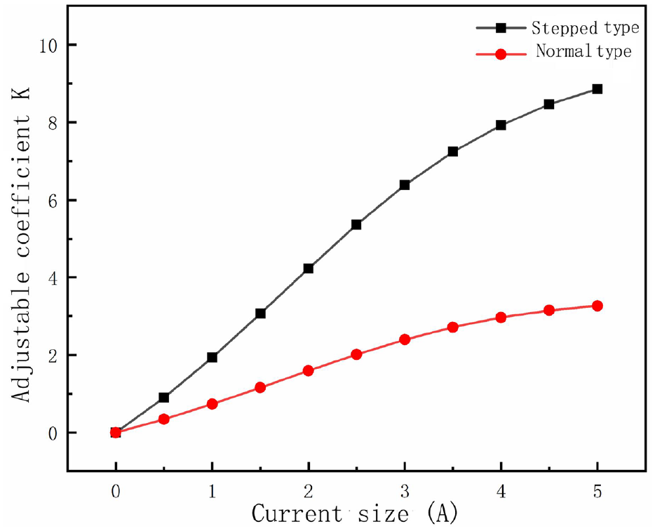
Comparison of adjustable coefficients between step type and ordinary type at different currents.
3.2.2 Influence of current size on damping performance
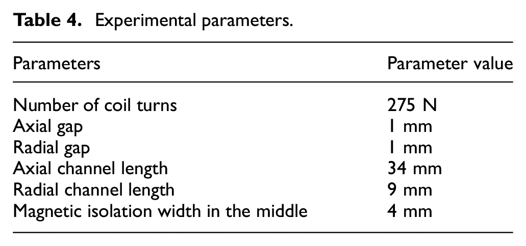
When the parameters are set in the following Table 4.
Experimental parameters.
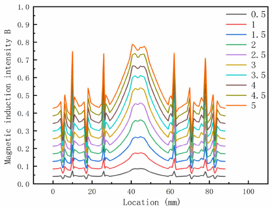
The maximum damping force F and the adjustable coefficient K are calculated based on the simulation results of Ansys software and the results are brought into the equations in Chapter 2. The change of the magnetic induction intensity in the damping gap under different current sizes is studied as shown in Figure 10.
The effect of current size on magnetic flux density.
It can be seen from Figure 10 that when the current passed to the excitation coil gradually increases from 0.5 to 5 A, the magnetic induction intensity in the damping gap of the liquid flow channel is increasing. The reason is that increasing the current is equivalent to increasing the magnetic flux, and the magnetic resistance in the damping gap is the same as before when the structure remains unchanged, so the magnetic flux density in the gap increases with the increase of the current. When the current reaches a certain level, the magnetic flux density reaches a saturation value, and increasing the current has little effect on its damping performance. Figures 11 and 12 show the effect of different currents on the output damping force and the adjustable coefficient.
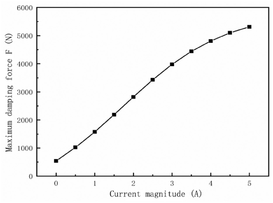
Influence of current size on damping force.
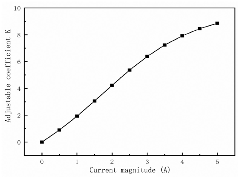
Influence of current size on adjustable coefficient.
It can be seen from Figure 11 that when the current increases from 0 to 5 A, the output damping force increases with the increase of the current. This is because increasing the current will increase the magnetic flux, and the magnetic resistance will remain unchanged when the structure remains unchanged, so the magnetic induction intensity in the damping gap is increasing, and the hysteresis damping force increases, but the viscous damping force is constant.
It can be seen from Figure 12 that when the current increases from 0 to 5 A, the adjustable coefficient K also increases with the increase of the incoming current. This is because the viscous damping force is constant when the structure remains unchanged, increasing the current will increase the magnetic flux, and the magnetic resistance in the gap remains unchanged, so the magnetic induction intensity in the damping gap increases. The increase of the magnetic induction will lead to an increase in the hysteresis damping force, but the viscous damping force remains unchanged.
3.2.3 Influence of axial clearance on damping performance
When the parameters are set in the following Table 5.
Experimental parameters.
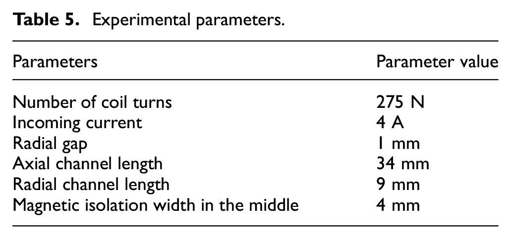
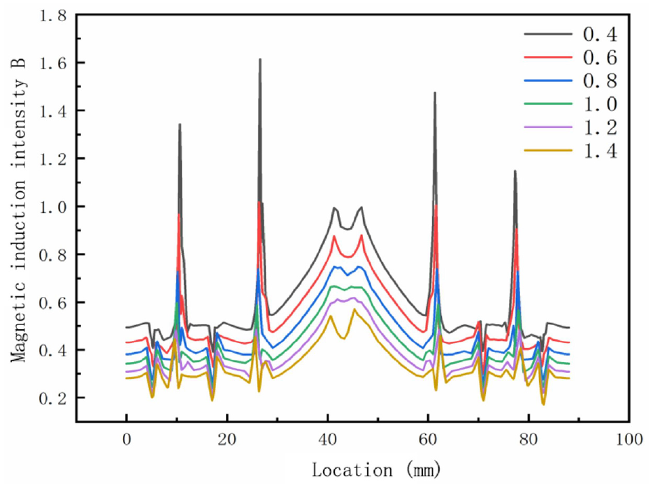
The maximum damping force F and the adjustable coefficient K are calculated based on the simulation results of Ansys software and the results are brought into the equations in Chapter 2. The changes in the magnetic flux density in different axial damping gaps are studied as shown in Figure 13.
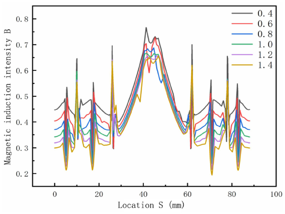
Influence of axial gap on magnetic flux density.
It can be seen from Figure 13 that when the axial damping gap in the liquid flow channel increases, the magnetic induction intensity in the axial damping gap decreases significantly. This is because when the axial damping gap increases, the magnetic resistance in the axial damping gap increases, and the total magnetic flux is constant, so the magnetic induction intensity of the axial damping gap decreases. The effects of different axial clearances on the output damping force and adjustable coefficient are shown in Figures 14 and 15.
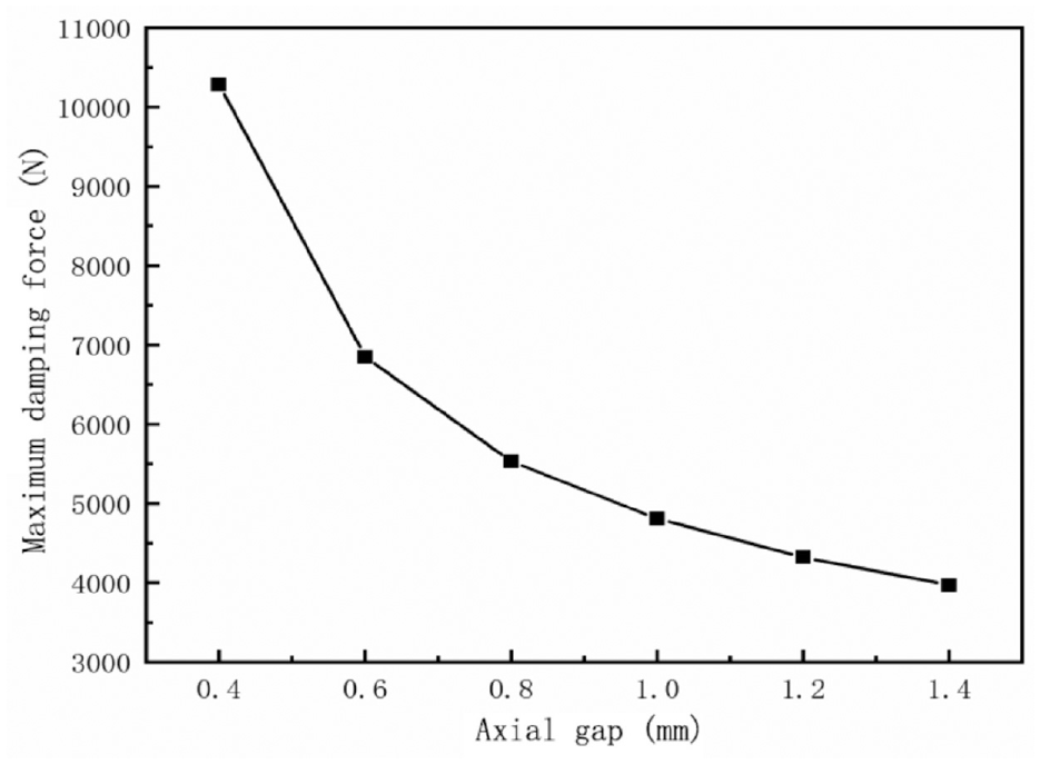
Influence of axial clearance on damping force.
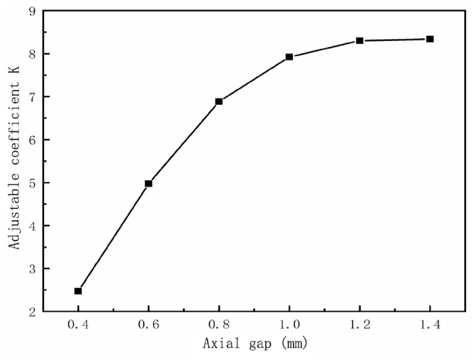
Influence of axial clearance on adjustment factor.
It can be seen from Figure 14 that when the axial damping gap increases from 0.4 to 1.4 mm, the magnetic induction intensity in the axial damping gap decreases with the increase of the axial damping gap. Both the viscous damping force and the Coulomb damping force are decreasing, so the maximum output damping force is continuously decreasing.
Figure 15 shows that the adjustable coefficient K increases with the increase of the axial damping gap in the liquid flow channel. The magnetic induction intensity in the axial damping gap in the liquid flow channel decreases with the increase of the axial damping gap, but the decreasing speed of the hysteresis damping force is much smaller than that of the viscous damping force, so the adjustable coefficient is on the rise.
3.2.4 Influence of radial clearance on damping performance
When the parameters are set in the following Table 6.
Experimental parameters.
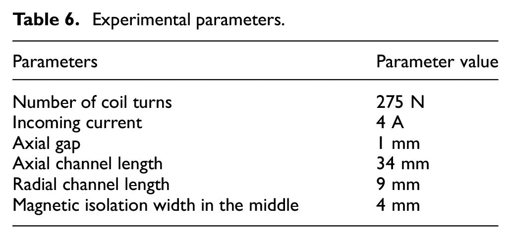
The maximum damping force F and the adjustable coefficient K are calculated based on the simulation results of Ansys software and the results are brought into the equations in Chapter 2. Figure 16 shows the variation of the magnetic flux density in different radial damping gaps.
Influence of radial gap on magnetic flux density.
It can be seen from Figure 16 that when the radial damping gap in the liquid flow channel increases from 0.4 to 1.4 mm, the magnetic induction intensity in the radial damping gap decreases with the increase of the gap. Because when the radial gap increases, the magnetic resistance in the gap increases, and the total magnetic flux is constant, so the magnetic induction intensity decreases. The effects of different radial damping gaps on the output damping force and adjustable coefficient are shown in Figures 17 and 18, respectively.
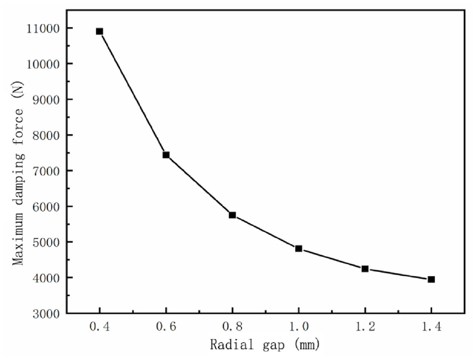
Influence of radial clearance on damping force.
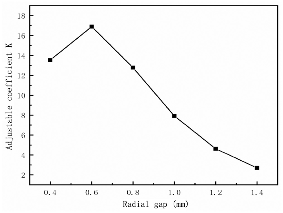
Influence of radial clearance on adjustable coefficient.
It can be seen from Figure 17 that when the radial gap increases from 0.4 to 1.4 mm, because the reluctance increases when the radial gap increases, But the total magnetic flux is constant, so the magnetic induction intensity decreases, and both the viscous damping force and the magnetic damping force are decreasing, so the output damping force is decreasing.
It can be seen from Figure 18 that when the radial clearance increases from 0.4 to 1.4 mm, the adjustable coefficient K first increases and then decreases continuously with the increase of the radial damping clearance. When the radial clearance is 0.6 mm, the adjustable coefficient is the largest. When the radial gap is less than 0.6 mm, the decreasing speed of the magnetic damping force is smaller than that of the viscous damping force, so the adjustable coefficient K shows an upward trend. When the radial gap is greater than 0.6 mm, the decreasing speed of the magnetic damping force is greater than that of the viscous damping force, so the adjustable coefficient K shows a downward trend.
3.2.5 Influence of axial channel length on damping performance
When the parameters are set in the following Table 7.
Experimental parameters.
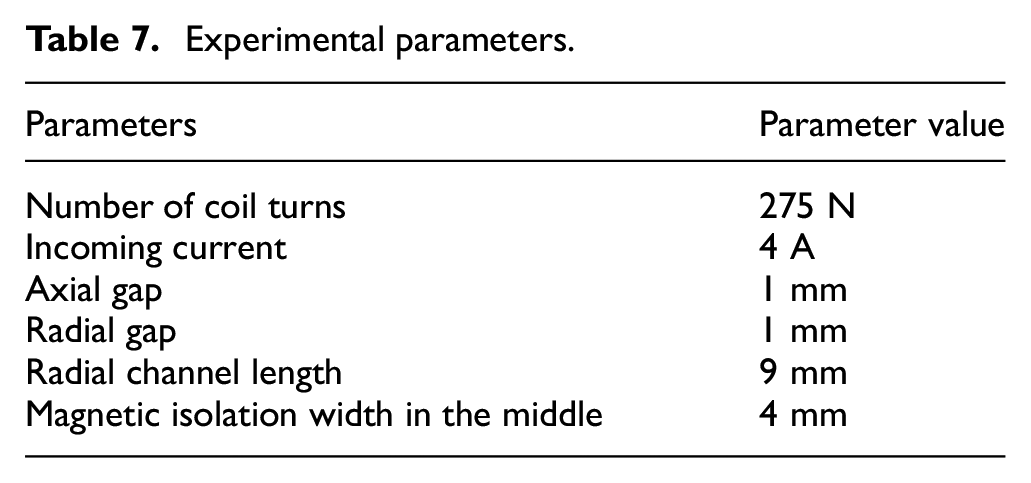
The maximum damping force F and the adjustable coefficient K are calculated based on the simulation results of Ansys software and the results are brought into the equations in Chapter 2. Figure 19 shows the change in the magnetic flux density in the damping gap for different axial channel lengths.
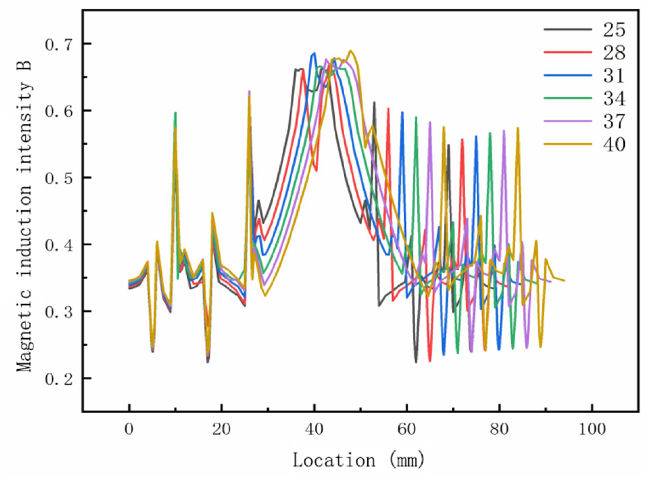
Influence of axial channel length on magnetic flux density.
It can be seen from Figure 19 that when the length of the axial passage increases, the magnetic induction intensity in the damping gap increases slightly, but the increase is slightly smaller. This is because the increase in the axial channel length will also indirectly lead to an increase in the reluctance, but the total magnetic flux is constant. However, the magnetic field lines increase through the middle magnetic conductive part, and the magnetic induction intensity in the gap also increases, so the increase is slightly smaller. The effects of different axial channel lengths on the output damping force and adjustable coefficient are shown in Figures 20 and 21, respectively.
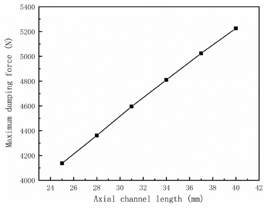
Influence of axial channel length on damping force.
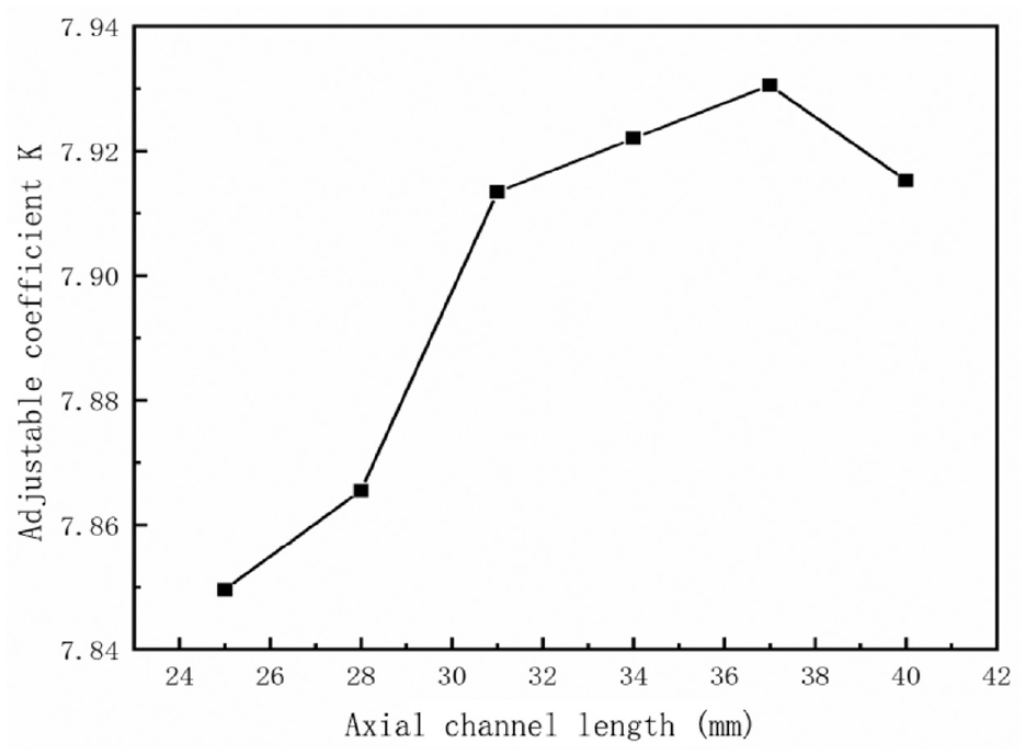
Influence of axial channel length on the adjustable coefficient.
It can be seen from Figure 20 that the damping force increases linearly with the increase of the axial channel length from 25 to 40 mm. This is because the length of the axial channel is the length of the magnetically conductive part in the middle. When the length of the axial channel increases, the magnetic induction intensity in the damping gap will increase, which indirectly increases the magnetically induced damping force.
It can be seen from Figure 21 that the adjustable coefficient K first increases and then decreases with the increase of the axial channel length. When the damping channel is less than 37 mm, the increasing speed of the hysteresis damping force is greater than that of the viscous damping force, so the adjustable coefficient shows an upward trend.
3.2.6 Influence of radial channel length on damping performance
When the parameters are set in the following Table 8.
Experimental parameters.
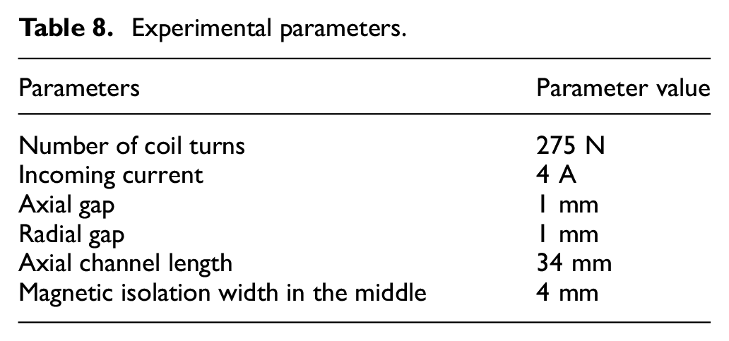
The maximum damping force F and the adjustable coefficient K are calculated based on the simulation results of Ansys software and the results are brought into the equations in Chapter 2. Figure 22 shows the variation of the magnetic flux density in the damping gap with different radial channel lengths.
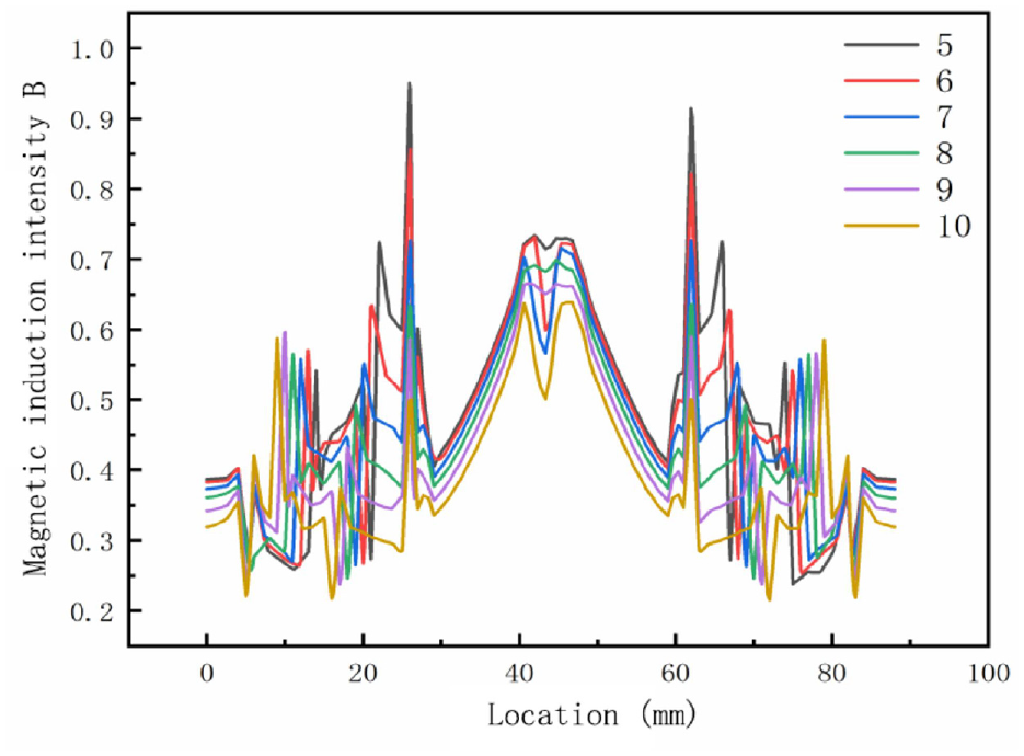
Influence of radial channel length on magnetic flux density.
It can be seen from Figure 22 that when the length of the radial channel increases, the magnetic induction intensity in the gap decreases. When the radial channel length increases to a certain extent, the magnetic induction intensity in the gap becomes very small. When the length of the radial channel decreases, although the magnetic induction intensity of the damping gap in the liquid flow channel increases to a certain extent, the length of the damping channel through which the magnetic field lines of the corresponding region pass vertically becomes shorter, thereby affecting the magnetically induced damping force. Figures 23 and 24 show the effects of different radial channel lengths on the output damping force and adjustable coefficient.
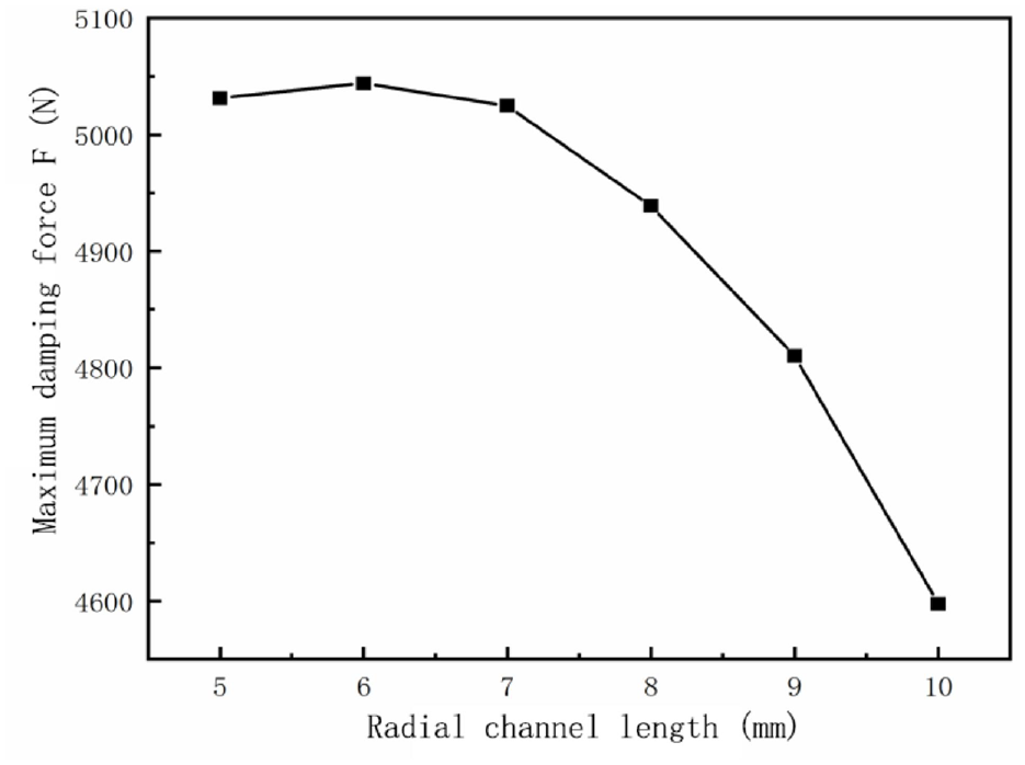
Influence of radial channel length on damping force.
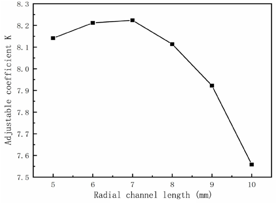
Influence of radial channel length on the adjustable coefficient.
It can be seen from Figure 23 that when the radial channel length increases, the output damping force first increases and then decreases. However, the first rising trend is relatively small, and then with the increase of the length of the radial channel, the length of the vertical line of magnetic force becomes larger, and its magnetic damping force may increase. However, when the length of the radial channel increases to a certain value, the magnetic induction intensity in the gap decreases, the magnetic damping force decreases, and the viscous damping force changes little, so the output damping force first increases and then decreases.
It can be seen from Figure 24 that the increasing speed of the most open hysteresis damping force is greater than that of the viscous damping force, and the adjustable coefficient K first shows an upward trend. When the radial channel length exceeds 7 mm, the hysteresis damping force begins to decrease, but the viscous damping force is still increasing, resulting in a decreasing trend of the adjustable coefficient K.
4. Test verification of damping characteristics
4.1 Experimental setup
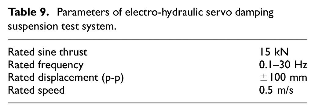
The magnetorheological damper performance test instrument adopts the electro-hydraulic servo damping suspension test system (HPM-V2500) to test the magnetorheological damper. Electro-hydraulic servo damping suspension experimental system consists of hydraulic pump station (HPU-60), vibration exciter, system bench, electro-hydraulic servo loading controller (VT-6106), and computer. The test site map is shown in Figure 25. The specific parameters of the electro-hydraulic servo damping suspension test system are shown in Table 9. The stepped bypass MR damper is shown in Figure 26, and the bypass MR valve is shown in Figure 27.
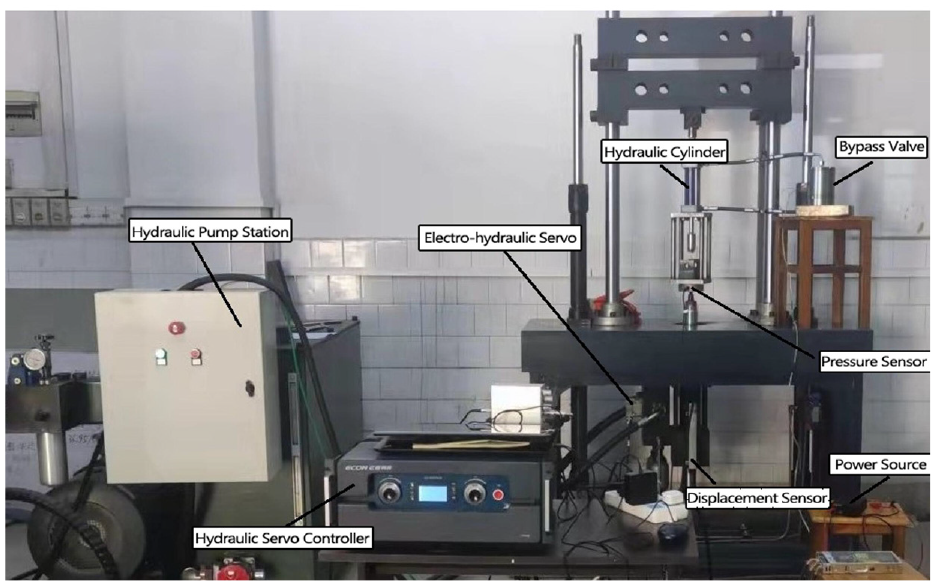
Electro-hydraulic servo damping suspension test system diagram.
Parameters of electro-hydraulic servo damping suspension test system.
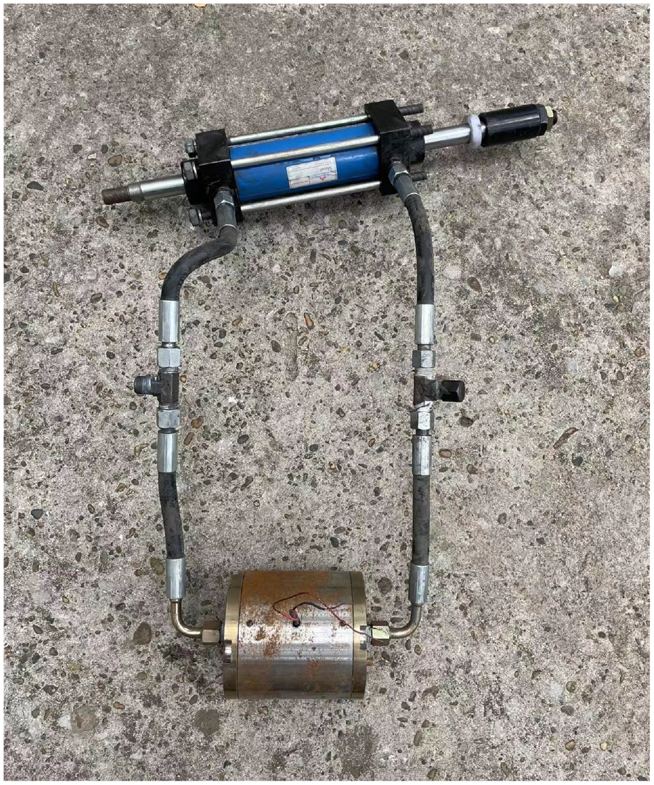
Stepped bypass magnetorheological damper.
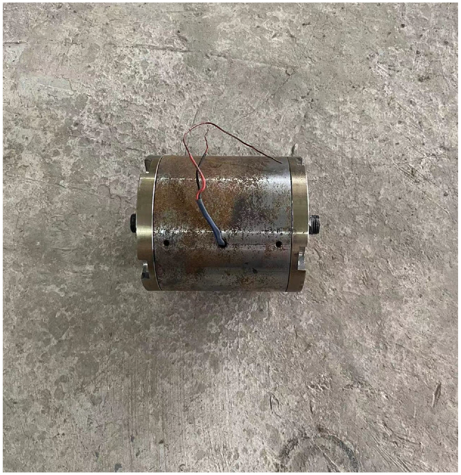
Bypass MR valve.
4.2 Analysis of test results
The magnetorheological damper designed in this paper is a bypass valve type magnetorheological damper, which consists of a hydraulic cylinder and a magnetorheological valve. Therefore, the performance of the bypass valve part is experimentally studied, and the performance change law of the bypass valve part of the magnetorheological damper is derived by measuring the 9 mm amplitude part. According to the above theoretical deduction, the output damping force is not related to the damper stroke. Therefore, only the amplitude within 9 mm was tested in the experiment.
4.2.1 Variation relationship of damping force without electricity
Test the damping force of the damper without power on. During the test, the power was turned off, the fixed frequency was 1 Hz, and the output damping force-displacement and damping force-velocity curves of the damper were measured when the amplitude was 3, 5, 7, and 9 mm respectively.
It can be seen from the Figures 28 and 29 that as the amplitude increases from 3 to 9 mm, the output damping force also increases. This is because the frequency is fixed and the amplitude affects the rate of movement of the piston rod of the hydraulic cylinder, when the amplitude increases, the movement rate of the piston rod also increases, resulting in an increase in the flow rate of the magnetorheological fluid, resulting in an increase in the viscous damping force, and finally an increase in the output damping force.
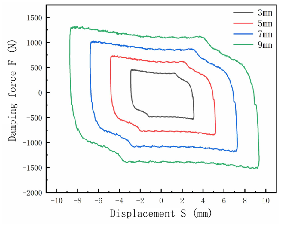
Relationship between damping force and displacement at different amplitudes.
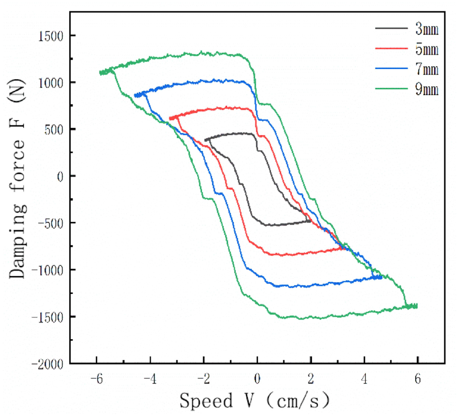
Relationship between damping force and speed at different amplitudes.
4.2.2 Variation relationship of damping force under the condition of frequency variation
When a current of 2 A is applied, the fixed amplitude is 5 mm, and the frequency is set to 0.5, 1, 1.5, and 2 Hz in turn, and the relationship curves of the output damping force-displacement and damping force-velocity are shown in the Figures 30 and 31.
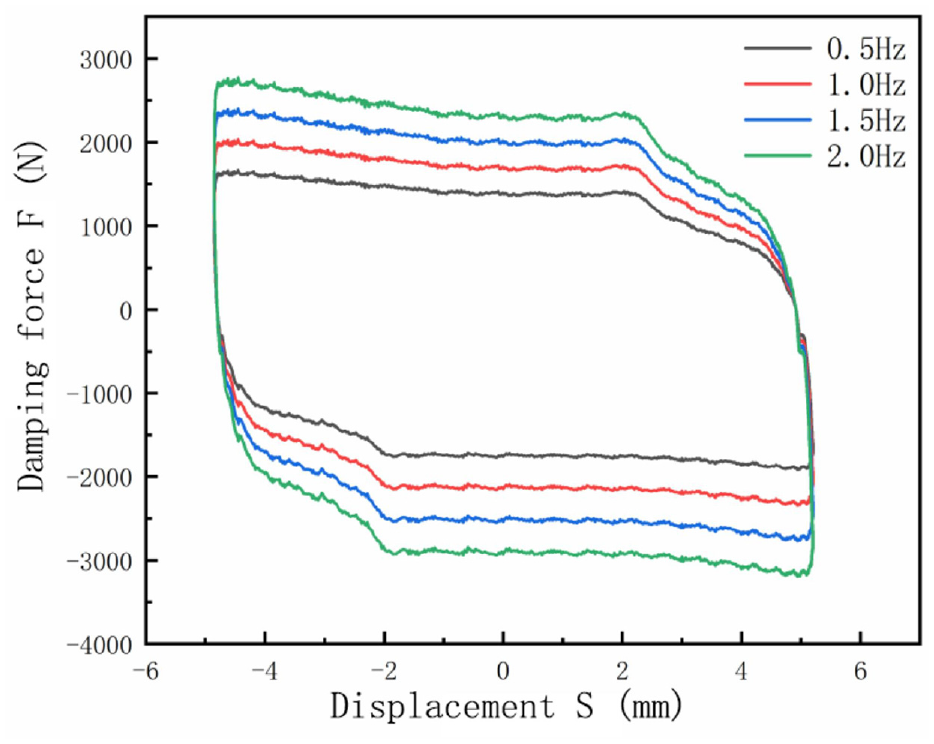
Relationship between damping force and displacement at different frequencies.
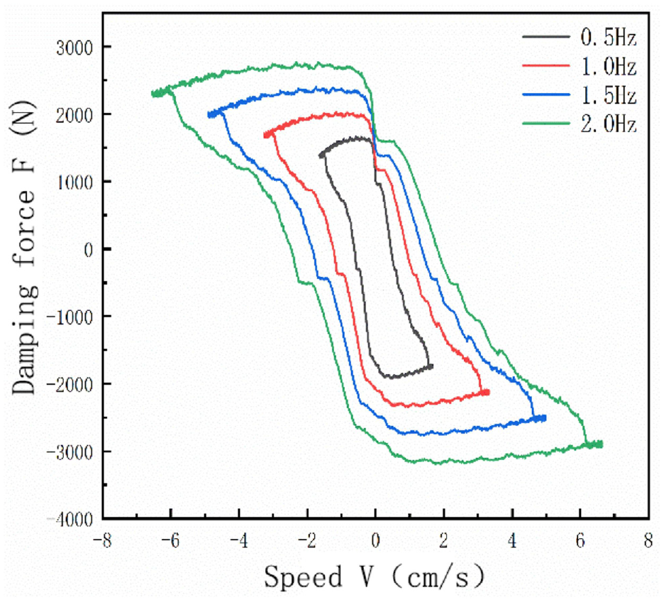
Relationship between damping force and speed at different frequencies.
When the frequency increases from 0.5 to 2 Hz, the movement rate of the piston rod is affected, and the flow rate of the magnetorheological fluid will increase because the movement rate of the piston rod, eventually the viscous damping force, which will be affected by the flow, becomes larger.
4.2.3 Variation relationship of damping force under the condition of amplitude variation
When the current is 2 A and the frequency is 1 Hz to the excitation coil of the stepped bypass magnetorheological damper, the amplitude is set to 3, 5, 7, and 9 mm in turn. The relationship between output damping force-displacement and damping force-velocity at different amplitudes is shown in the Figures 32 and 33.
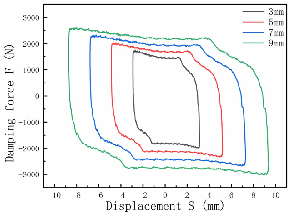
Relationship between damping force and displacement at different amplitudes.
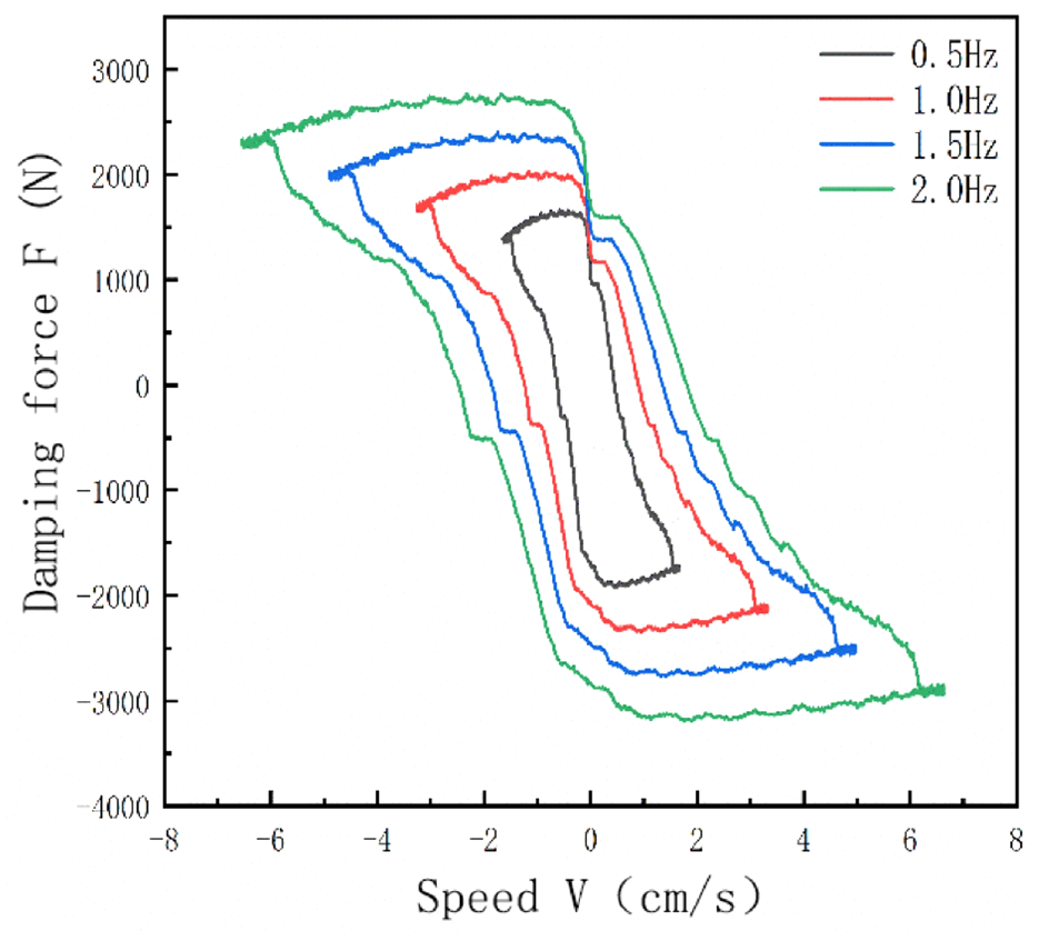
Relationship between damping force and speed at different amplitudes.
It can be seen from the figure that as the amplitude increases from 3 to 9 mm, the output damping force increases gradually. The amplitude affects the movement rate of the piston rod of the hydraulic cylinder. When the amplitude increases, the movement rate of the piston rod also increases, resulting in an increase in the flow rate of the magnetorheological fluid, which increases the viscous damping force. When the current to the excitation coil remains unchanged, the hysteresis damping force affected by the magnetic field also remains unchanged, which eventually leads to an increase in the output damping force with the increase of the amplitude.
5. Parameter optimization
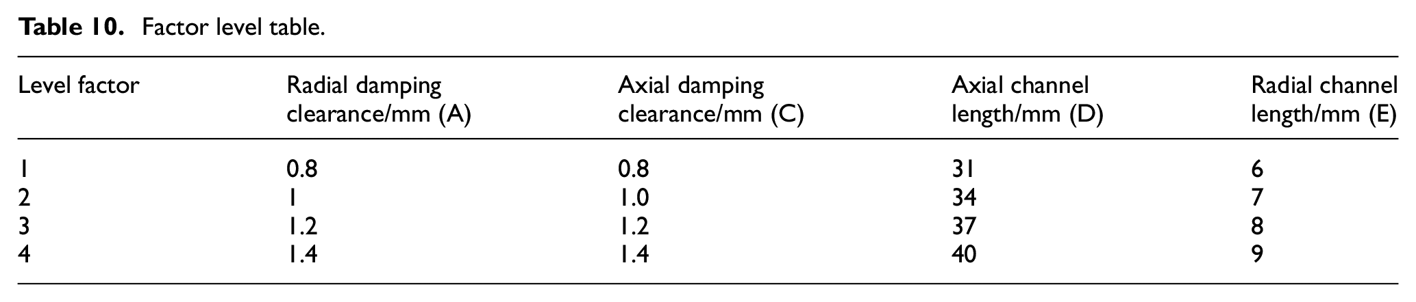
Orthogonal experimental design, an experimental design method to study multiple factors and levels. Orthogonal optimization is used to study the importance of the influence of each factor on the damping performance in different situations (Deng et al., 2022a). The purpose of this orthogonal test is to find the optimal structure size of the stepped bypass magnetorheological damper. The quantitative index refers to the objective function G containing the weight coefficient. The larger the value of G, the better. The factors affecting the performance of the stepped bypass MR dampers are five factors: radial gap, axial gap, radial channel length, axial channel length, and medium interval magnetic width. When the magnetic separation width is 2, the output damping force F and the adjustable coefficient K are the largest, but in the actual processing process, the middle part will be too weak and damaged, so it is more appropriate to choose the magnetic separation width of 4 mm in the actual process. The level factors selected in this paper are shown in Table 10.
Factor level table.
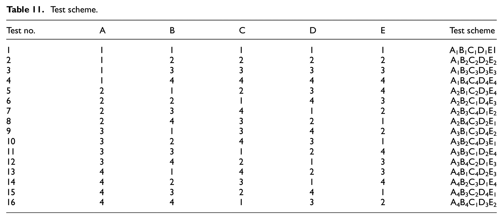
According to the number of factors and levels, choose the appropriate orthogonal table. This orthogonal test has five factors and four levels, and the orthogonal table that meets the requirements is table L16(45). The test scheme is shown in Table 11.
Test scheme.
The formula of the objective function G is as follows:
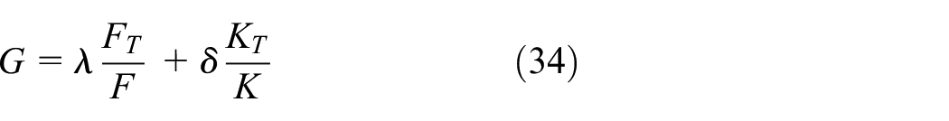
Where,
The constraints to determine the objective function G according to the actual situation are as follows:


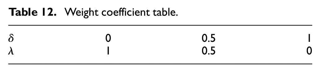
According to the orthogonal table, the electromagnetic field simulation experiment is carried out to obtain the objective function G. The weight coefficients of the two different cases in this paper are shown in Table 12.
Weight coefficient table.
5.1 Results under the first weight coefficient
5.1.1 Range analysis
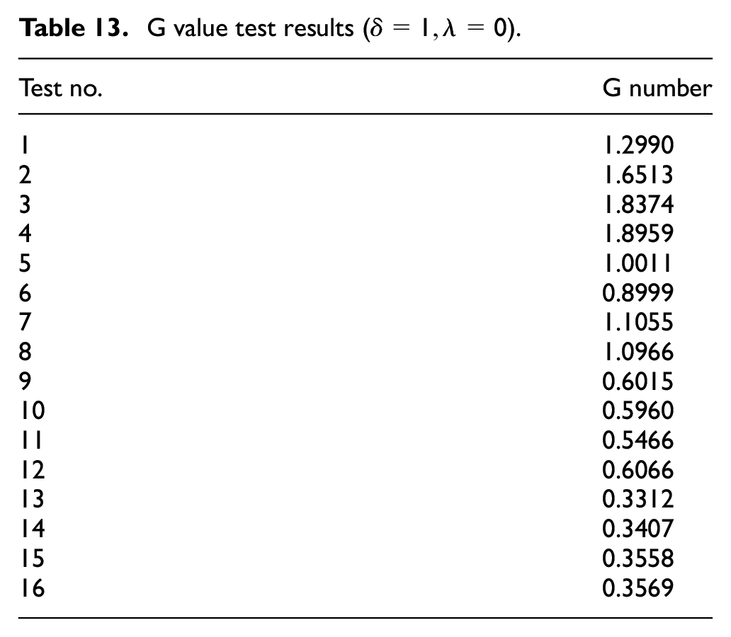
When
G value test results (
Range analysis of test results (
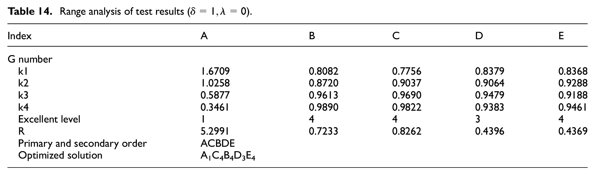
A larger range value reflects the greater influence of the factor corresponding to that R value on the test index. It can be seen from Table 14 that the range is RA > RC > RB > RD > RE, so the primary and secondary order of the factors affecting the orthogonal test index is: ACBDE. Finally, the optimal level combination of each factor is obtained, that is A1C4B4D3E4.
5.1.2 Analysis of variance
When
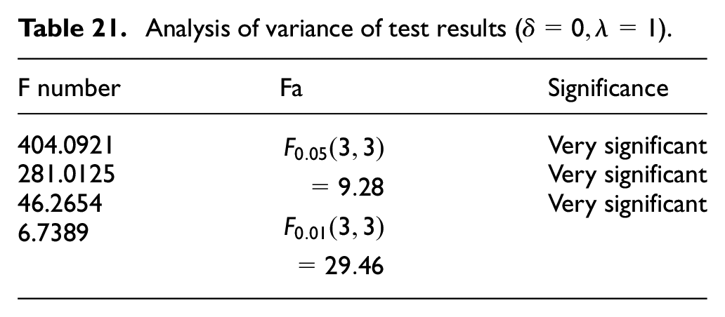
Analysis of variance of test results (
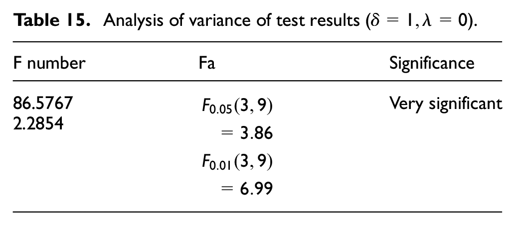
Through the calculation formula of variance, the variance analysis results of each factor are calculated, and the F test method is used to test that factor A has a very significant impact on the test results, while factors B, C, D, and E have no significant impact on the test results. This shows that the A factor radial clearance has a great effect on the G value, the C factor axial clearance has a great effect on the G value, and the D factor axial passage length and the E factor radial passage length have a certain effect on the G value.
5.2 Results under the second weighting coefficient
5.2.1 Range analysis
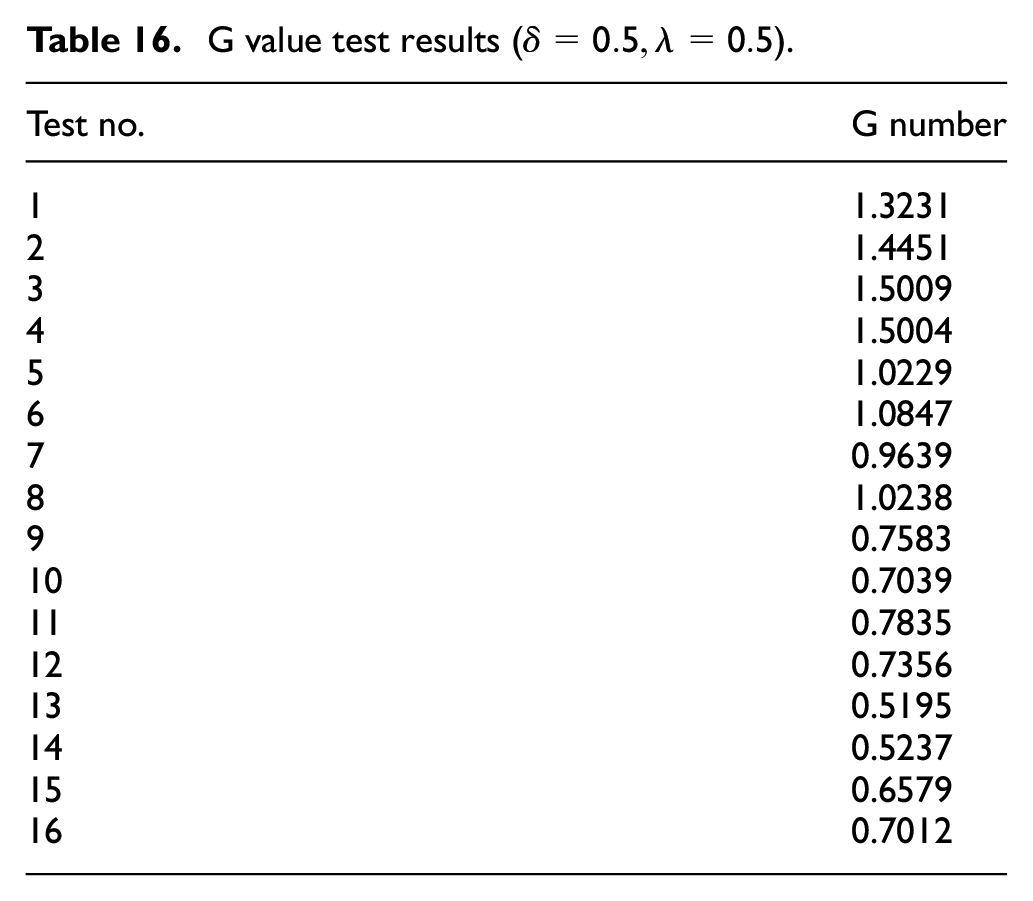
When
G value test results (
Range analysis of test results (
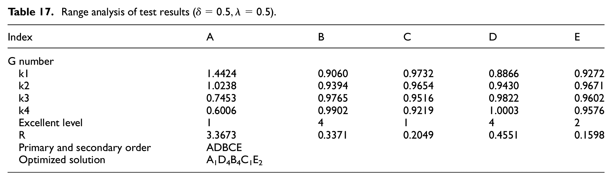
A larger range value reflects the greater influence of the factor corresponding to that R value on the test index. From Table 17, it can be seen that RA > RD > RB > RC > RE, so the main order of factors’ influence on the index of orthogonal test is: ADBCE. Finally, the optimal level combination of each factor is obtained, namely A1D4B4C1E2.
5.2.2 Analysis of variance
When
Analysis of variance of test results (
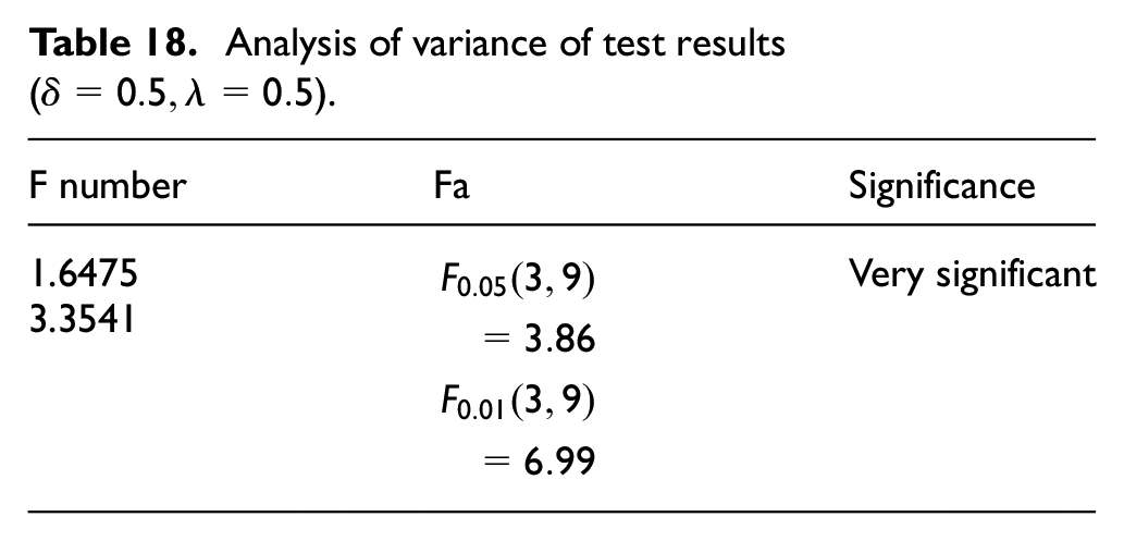
The ANOVA results of each factor were calculated by the formula of variance, and the test using F-test showed that factor A had a highly significant effect on the test results, and factors B, C, D, and E had no significant effect on the test results. This indicates that the A-factor radial clearance has a very large effect on the G-value, the D-factor axial channel length has a large effect on the G-value, and the C-factor axial clearance and the E-factor radial channel length have some effect on the G-value.
5.3 Results under the third weight coefficient
5.3.1 Range analysis
When
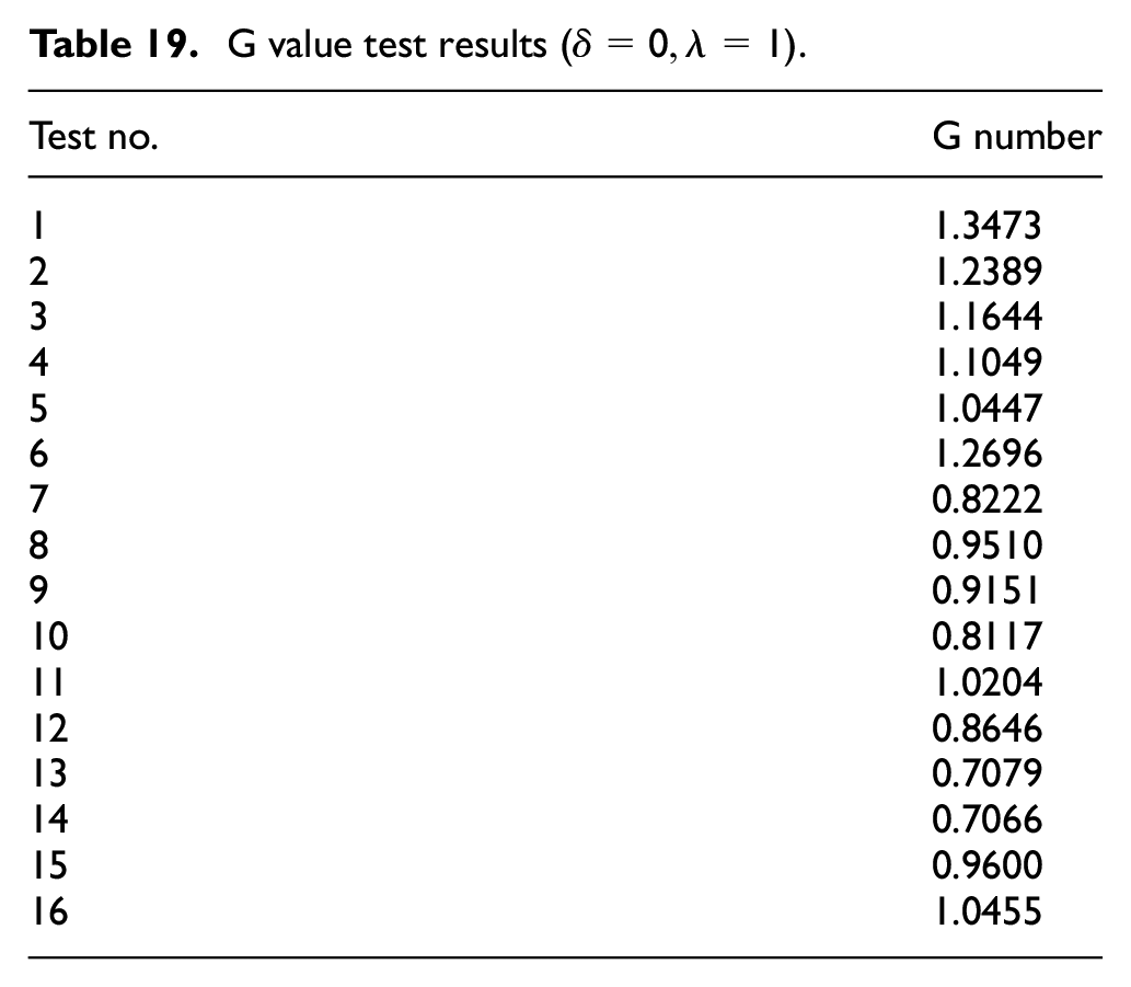
G value test results (
Range analysis of test results (
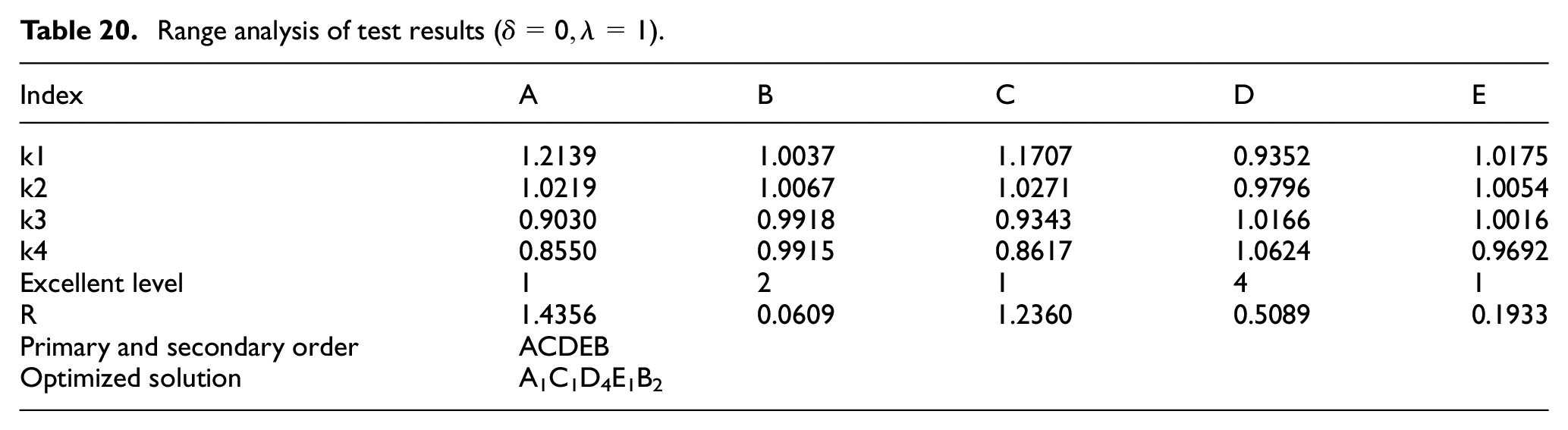
A larger range value reflects the greater influence of the factor corresponding to that R value on the test index. From Table 20, it can be seen that RA > RC > RD > RE > RB, so the primary and secondary order of the factors affecting the orthogonal test index is: ACDEB. Finally, the optimal level combination of each factor is obtained, that is, A1C1D4E1B2.
5.3.2 Analysis of variance
When
Analysis of variance of test results (
Through the calculation formula of variance, the variance analysis results of each factor are calculated, and the F test method is used to test that factors A, C, and D have a very significant impact on the test results, while factors B and E have no significant impact on the test results. This shows that the A factor of radial clearance, the C factor of the axial clearance, and the D factor of the axial channel length have a great effect on the G value, and the E factor of the radial channel length has a great effect on the G value.
5.4 Comparison before and after optimization
The best combination obtained for the first weighting coefficient of
The best combination obtained for the second weighting coefficient of
The optimal combination obtained for the third weighting coefficient of
The damping forces and adjustable coefficients calculated from the relevant equations are greater than those of the pre-optimization scheme. As shown in Figure 34. The first weighting factor of
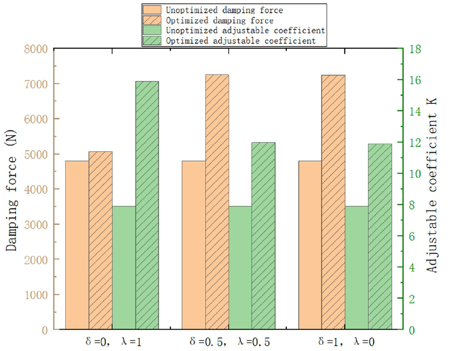
Comparison before and after optimization.
6. Conclusion
In this paper, a new type of stepped bypass magnetorheological damper is proposed and designed. According to its mechanical model, preliminary hydraulic design and magnetic circuit design are carried out, and the electromagnetic field simulation method is used to study the influence of different key parameters such as damping gap, damping channel length, and current magnitude on the damper performance. The damper is tested and verified. Orthogonal experiment optimization was carried out, and the optimization results compared with the former results. Finally, the following conclusions are drawn.
In the case of no power supply, the frequency remains constant, and as the amplitude increases from 3 to 9 mm, the output damping force increases. When the current and amplitude are kept constant, and the frequency increases from 0.5 to 2 Hz, the output damping force increases. When the current and frequency are kept constant, and the amplitude increases from 3 to 9 mm, the output damping force also increases.
When the current is 0 A, the output minimum damping force is about 700 N. When the input current reaches 4 A, the output damping force will not increase significantly. When the input current is 5 A, the output maximum damping force is about 4500 N, and the adjustable coefficient K is about 5.4.
The structure is optimized by orthogonal experimental design. The optimized damping force is 7249 N, which is 50.7% higher than that before optimization, and the adjustable coefficient K is 1.37 times that before optimization. The range of damping force before optimization is 607–4809 N, and the range of damping force after optimization is 610–7249 N, which is 57.9% wider than that before optimization. The results fully show that the damper with optimized structure size has better maximum output damping force and adjustable coefficient than the damper before optimization.
Footnotes
Declaration of conflicting interests
The authors declared no potential conflicts of interest with respect to the research, authorship, and/or publication of this article.
Funding
The authors disclosed receipt of the following financial support for the research, authorship, and/or publication of this article: The authors gratefully acknowledge the support of the National Nature Science Foundation of China (Grant No. 51905114), the support of the Science and Technology Project of Guangxi Province (Grant No. 2020GXNSFAA159042).