
Abstract
This work presents a magnetorheological (MR) damper applicable to the landing gear system in the aircraft. The proposed MR landing gear (MRLG) is modeled as a two degrees of freedom (2-DOF) system for the drop performance evaluation. A mathematical model of the governing equations is then formulated considering a flow path whose pressure depends on the major and minor losses. The flow path of MR fluid is composed of annular orifice and bypass as the required damping force for compression and extension is much different, and relief valve operates in conformity with the motion direction of the piston rod. An entry region is added to guarantee precise controllability of the field-dependent damping force. In addition, the magnetic intensity and total loss coefficient are estimated using magnetic analysis and computational fluid dynamics tools, respectively. It is demonstrated from the drop test based on the Federal Aviation Regulation (FAR) Part 23 that the shock struct efficiency (SSE) of the proposed MRLG can be increased from 42% at zero current to 84% at 1 A, and the agreement between simulation and experimental results is excellent showing similar pneumatic force, strut force, and jerk behavior which validates the accuracy of the proposed model.
Keywords
1. Introduction
Of all elements in the aircraft, the landing gear is the most crucial system upon landing, acting as an intermediate structure between the aircraft’s fuselage and runway. This system should ensure the boarding feeling of passengers and stability as well as maneuverability (Currey, 1988). The only way to improve these is to dissipate the mechanical energy sufficiently in the landing gear to minimize the impact and vibration transmitted to the fuselage (Gharapurkar et al., 2013). The up-to-date oleo-pneumatic shock absorbers mainly provide good landing performance, but it is unsuitable for landing in severe conditions such as harsh weather, sink speeds, and road surfaces. Therefore, conventional landings operate only on well-paved roads and airports. Besides, passive suspensions are difficult to provide both good landing impact cushioning and improved frequency characteristics during taxiing (Hitch, 1981). Even in taxiing on well-paved runways, the problem of overlapping the natural frequency of the aircraft structure and human body causes severe degradation of the ride comfort (Krüger et al., 1997). The magnetorheological (MR) damper can be a solution to this problem in that it can tune the natural frequency and magnitude of the system depending on the input current (magnetic field intensity).
To guarantee stable landing in various conditions, some studies on replacing aircraft landing gear with MR dampers have been progressing rapidly in recent years (Han et al., 2019, 2020; Kang et al., 2021b, 2021c). Developed by Jacob Rabinow in 1948 (Rabinow, 1948), MR fluid (MRF) is a mixture of micro-sized carbonyl iron particles and carrier oil containing silicone, hydrocarbon, etc. (Carlson, 2002; Goncalves et al., 2006). An external magnetic field polarizes the suspended particles inside the fluid, and the induced dipole forms a structure that inhibits the flow of the fluid (Carlson and Jolly, 2000). Thanks to its tunable nature, MRF can be analyzed based on the Newtonian model in the absence of the external field and the Bingham-plastic or Herschel-Bulkley shear model in the presence of the external field (Gamota and Filisko, 1991; Lee et al., 2002). Therefore, MRF is classified into a smart fluid and is currently being studied in various research fields (Lee et al., 2019; Park and Choi, 2021; Sohn et al., 2018).
In particular, the MR damper is the most used in the field of vibration systems among various MR applications. The MR damper is filled with MRF, and the permanent magnet or the electromagnet is built-in inside the damper (Yao et al., 2002). The field-dependent damping force can be tuned depending on the magnetic field of MRF (Kim et al., 2020; Lee and Choi, 2019). The hysteresis of the field-dependent force may occur in the low-speed region during exciting MR damper, and the Bouc-Wen model is frequently used to simulate the phenomenological hysteresis (Choi and Han, 2005; Spencer et al., 1997). By utilizing the Schwarz-Christoffel transformation, the field-dependent force is derived analytically for a multi-layered magnetic core model in MR damper by considering the fringing effect and nonlinearity of the magnetic field-intensity (B-H) relationship (Yoon et al., 2021). An amount of MR energy absorber (MREA) technologies has been developed over the last 15 years. MREAs have been developed based on dimensionless numbers such as the Bingham number to realize optimal soft landing by dissipating shock energy when reaching a constant stroke regardless of the impulse (Wereley et al., 2011). MREA capable of resting an impulse of up to 300 N·s within 30 ms was built based on a nonlinear hydrodynamical model, and the transient impact response has been analyzed experimentally (Mao et al., 2013). Moreover, recently the cavitation behavior was mathematically modeled for the MR damper, and its effectiveness was validated via experiment; It is observed in the MR damper that the hysteresis damping is dependent not only on the effect of the magnetization but also on the cavitation effect (Kang et al., 2022).
MR landing gear (MRLG) is a kind of MR damper that replaces the oil of the oleo-pneumatic shock absorber with MRF (Batterbee et al., 2007a). There are various examples of attempts to substitute MRLG for conventional landing gear. An MR damper similar to the typical landing gear was manufactured in a compact form, and the pressure losses for the derived model and experimental data have been compared and considered under low-speed conditions (Batterbee et al., 2007b). The MRLG for a helicopter was modeled using the Bingham-plastic model, and an impact test has been performed with the damper using the synthesized MRF (Powell et al., 2013). The damping force of a minimum of 3 kN and a maximum of 38 kN was realized through an experiment by designing a helicopter MRLG without the pneumatic chamber, and the structure’s acceleration has been reduced effectively by using bang-bang and continuous controls (Choi et al., 2016). Based on the aircraft’s mechanical energy, a feedback control logic and performance simulation have been studied to calculate the desired force of the MRLG (Yoon et al., 2020). However, it is not sufficient until now to experimentally validate the landing performance of the MRLG, which can be operated at a fast sink speed corresponding to actual landing conditions. This issue is directly related to drop tests at various sink speeds according to Federal Aviation Regulation Part 23 (FAR 23) (Federal Aviation Regulations, 1989). Furthermore, the study on MR damper appliable to the aircraft landing gear system which can produce the maximum damping force up to 30 kN with low initial pneumatic pressure is considerably rare.
Consequently, the main technical contributions of this work are to formulate and optimize the 2-DOF MRLG model for the evaluation of the drop performance and validate the model via drop test. Therefore, sophisticated or robust control strategies such as sliding mode controller which can apply to the proposed semi-active control system under the semi-active condition did not considered (Do and Choi, 2022). Instead, the modeling accuracies between the proposed model and measurement are evaluated at various sink speed, different unsprung mass and input current
As a first step, it is derived a mathematical model governing the motions of the MRLG considering the pressure (major and minor) losses that is generally neglected in the MR damper model applicable to vehicle suspension systems. Subsequently, A 2-DOF MRLG dynamic model containing the pneumatic force, strut force, and ground force is established. In compliance with part FAR 23, the shock strut efficiency (SSE), which directly represents the performance of the aircraft landing gear system, is tested up to the sink speed of 3.05 m/s and compared with the simulation results under several drop mass: 640, 680, and 720 kg. In addition, the jerk motion of the MRLG is evaluated with and without input current to identify SSE improvement of the proposed system.
2. Mathematical modeling of MR landing gear
Figure 1 depicts the configuration of MR landing gear (MRLG). The MRLG is designed for the 3000 lbs. (1400 kg) class aircraft’s main landing gear system. The columns, braces, and side strut are jointed to the main strut support and distribute the aircraft’s load, connecting the MRLG and the aircraft fuselage with the trunnion. The side strut is connected to the landing gear drive system to help the gear retraction. The torque link suppresses the relative rotation between the main strut and the rod. In addition, the tire axle is connected to the tire and wheel, and a brake assembly can be installed. In a modified form of a single-ended monotube MR damper, the gas chamber is separated from MR fluid (MRF) by the separator inside the rod to prevent cavitation behavior. The piston rod is exposed through the rod gland at the bottom of the main strut. Chambers 1 and 2 are divided by the MR valve (MRV) on the piston head. The orifice and bypass are located inside and outside the MRV, respectively, and MRF can flow through these flow paths. The electric wire extends over the MRV and exits through the cable gland of the cap. The seal components are installed on the piston head, rod gland, and separator to prevent leakage and implement the operating pressure. In the figure, A1 and A2 are the cross-sectional area of chamber 1 and the outer area of the rod, respectively. There are some additional design requirements for the MRLG. First, high damping force is required to dampen the impact of the fuselage during landing. It should be considered that most of the impact energy is dissipated in the first compression process due to the high sink speed. On the other side, a fast extension is required to improve tire grip with low damping force. The relief valve can help to implement these damping characteristics. Second, structural MRV should be designed corresponding to a falling velocity of 3.05 m/s (Federal Aviation Regulations, 1989). Third, the angle of the torque link should not exceed 135° (Currey, 1988).
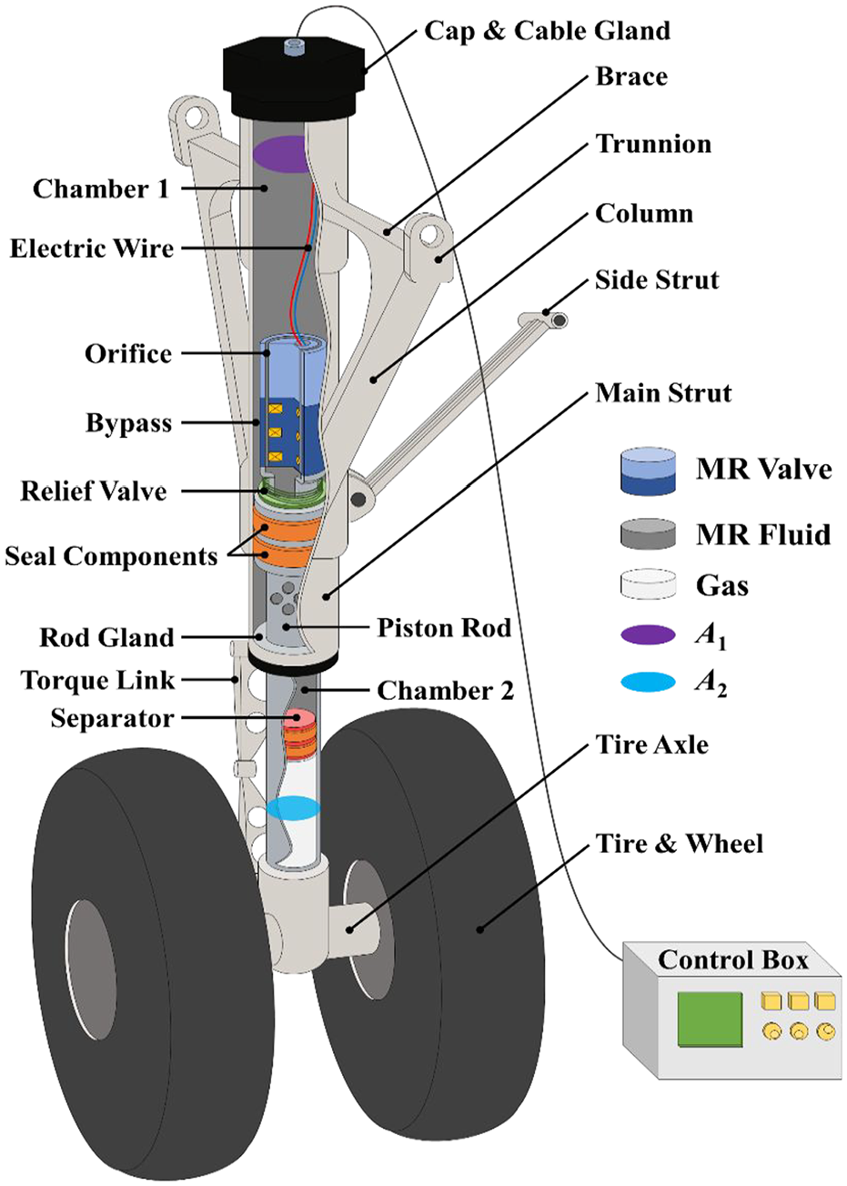
Configuration of MR landing gear (MRLG).
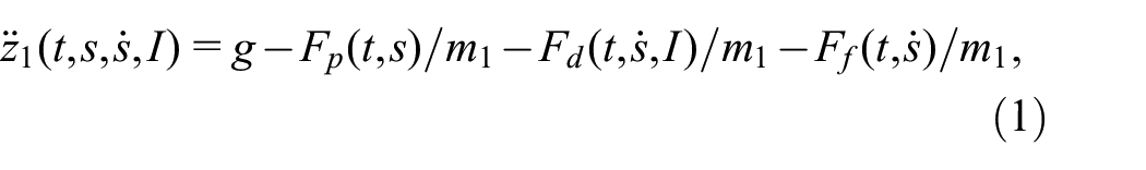
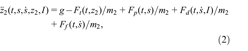
In order to imitate the vertical drop test, the landing gear system is modeled with two degrees of freedom (2-DOF), as shown in Figure 2. The aircraft drop model is composed of MATLAB code, a numerical analysis program. The system response of the landing gear can be analyzed by solving the differential equation numerically. The equations of motion for sprung and unsprung masses are:
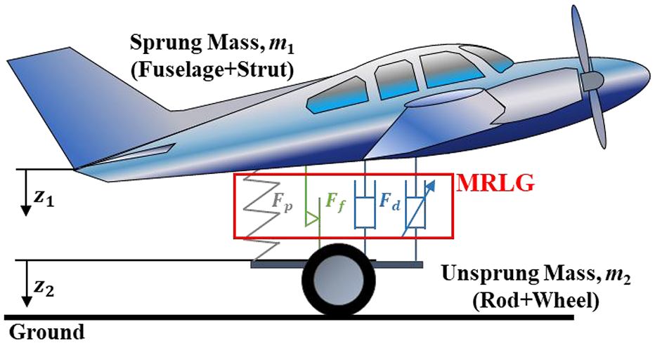
2-DOF MRLG model for drop simulation.
where t, g, and I are time, gravity acceleration, and input current; z1 and z2 are displacement of sprung mass (sum of aircraft fuselage and strut masses, m1) and unsprung mass (assembly mass of MRV, piston rod, wheel, and tire, m2), and

where kt and κ are the tire stiffness coefficient and index for the tire-deflection process, and
As shown in Figure 2, the strut force acting on the MRLG is classified into three categories: pneumatic force Fp, damping force Fd, and friction force Ff. The pneumatic force Fp is derived from the adiabatic processes for the ideal gas, assuming that the separator is compressed quickly enough after touchdown immediately:
where P0 and Pa are the initial inner pressure (or initial pneumatic pressure) and atmospheric pressure, V0 is the gas chamber volume at fully extended, and γ is the ratio of the specific heats, respectively.
Figure 3 shows the cross-section of the MRV, magnetic field, and streamlines in the orifice and bypass. The coordinate system of MRV is cylindrical and consists of flow (x-axis), radius (r-axis), and rotational axes. It is assumed that MRF flows along the x-axis only to compensate for the internal volume change caused by rod displacement. The proposed MRV consists of inner and outer magnetic cores, solenoid coils, and entry. The magnetic core is a kind of electromagnet that helps a magnetic field to act effectively on the magnetic pole zone of MRF. The magnetic field can be controlled depending on the input current since the solenoid coil is wound around the inner core. In this work, multi-core type is used in which the solenoid is divided into three parts. Therefore, the magnetic poles are four parts with lengths of Lp,1, Lp,2, Lp,3, and Lp,4, as shown in Figure 3. The orifice and bypass formed by the arrangement of inner and outer cores are annular flow paths, thereby having mean circumference diameter D and gap size d, respectively.
Schematic diagram of MR valve (MRV).
Notably, the relief valve in Figure 1 increases the pressure in chamber 1 by blocking the bypass flow during compression, whereas the pressure in chamber 2 is relieved by allowing the bypass flow during extension. Thanks to the relief valve, MRF flows only through the orifice when compressed (blue streamline) and simultaneously to the orifice and bypass when extended (red streamline). Therefore, the valve helps to realize the asymmetry of the damping force. The entry part is also installed. The entry length is long enough so that the magnetic core in Figure 3 is not located in the entrance region (Yang et al., 2002), installed to one side only since the region is negligible during extension. Besides, the effects of fluid compressibility and hydrodynamics are disregarded since there is a minor error between the cavitation model (Kang et al., 2022) and the model to be described later, and it is meaningful to prove and secure the model validity of the pressure loss model.
The following pressure loss models satisfy the annular Poiseuille laminar flow in the orifice and the annular Poiseuille-Couette laminar flow in the bypass. In addition, it can be approximated as a parallel-plate flow when the ratio of inner and outer diameters of an annular flow path exceeds 0.8 (Lundgren et al., 1964). Based on the preceding conditions, both major and minor losses are considered in the compression condition (Kang et al., 2021a). Under the compression, the total pressure loss is as follows:
where ρ and η are MRF’s density and dynamic viscosity, ΣK is total system loss near the MRV (dimensionless), do is orifice gap, ΣLp is total magnetic pole length (Lp,1 + Lp,2 + Lp,3 + Lp,4), L is MRV length,
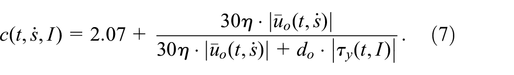
Due to the fast stroke and significant flow rate at the orifice, the minor loss coefficient is considered when compressed. On the other hand, the flow is splitted into the orifice and bypass, and the fluid velocities in the flow paths are slowed down. Hence, the major loss is considered only acting on the annular orifice and bypass in the extending condition. Under the extension, the relations between flow velocity and pressure loss in the orifice and bypass are as follows (Kang et al., 2022):
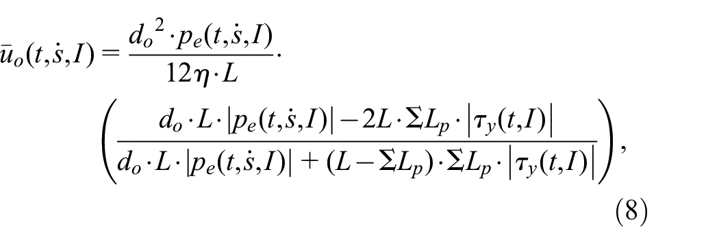
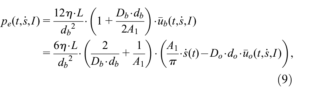
By solving equations (8) and (9), the pressure loss during extension is summarized as follows:
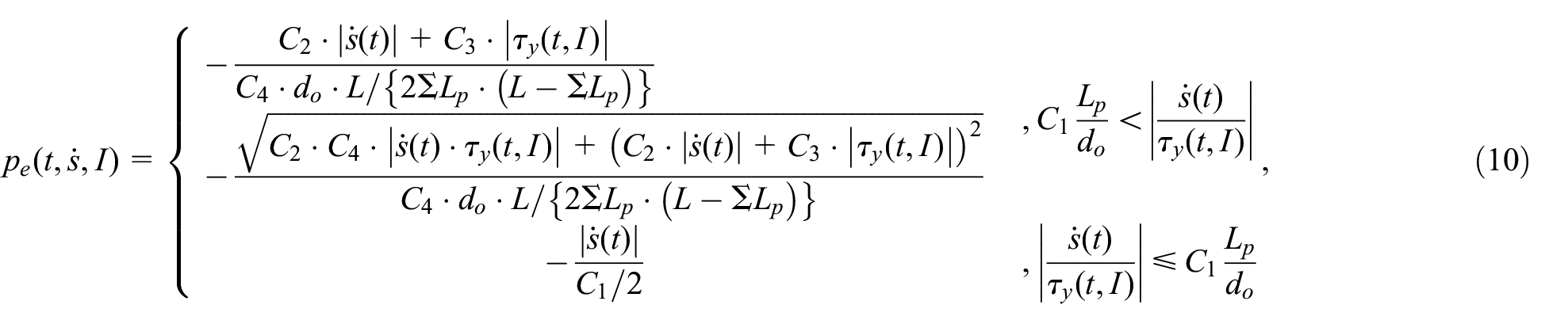
where the coefficients for C are for the viscous and geometric properties, defined as follows:
Finally, the damping force in compression and extension are:
Ignoring the friction force Ff, the strut force can be calculated as the sum of Fp and Fd.
3. Magnetic analysis and parameter optimization
3.1 Magnetic analysis
The finite element analysis is performed using the ANSYS MAXWELL (Electronics Desktop 2019 R1) program to analyze the magnetic field in the MRV. The magnetic field density-intensity (B-H) curve refers to the LORD Corporation’s (2019) datasheet for MRF-132CG. The materials of the MRV and the relief valve are as follows: Inner and outer cores are AISI1008 steel; the entry is AL6061-T6; The relief valve parts are SUS304; The solenoid coil is made of polyester enameled copper wire (PEW) of AWG27 standard, and it is wound about 1300 turns. The corresponding B-H curves and relative permeabilities are used for each material. The B-H curves of MRF-132DG and AISI1008 are shown in Figure 4. The relative permeabilities of paramagnetic materials, AL6061-T6, SUS304, and copper, are all set by 1. The magnetic analysis conditions are set as follows: The solution type is magnetic transient; The basic mesh number of the orifice is 15; Eddy effects and core loss are activated; nonlinear residual is set as 10−6. In Figure 5, the magnetic intensity of MRF is obtained by the magnetic analysis (Figure 5(a)) and curve-fitted (Figure 5(b)). The approximated magnetic intensity H for the input current I and orifice thickness do is determined as an exponential expression, as follows:

where the ranges of do and I are 1–2 mm and −2 to 2 A, and the units of do, I, and H are millimeter, Ampere, and kA/m. The above equation holds at total pole length ΣLp of 49.4 mm. The curve-fitted yield stress

In the above, the range of H is from −300 to 300 kA/m, and the units of
B-H curves for MRF-132DG and AISI 1008 steel.
Magnetic intensity contours for orifice gap and input current: (a) magnetic field analysis and (b) approx. solution.
Next, total system loss on the MRV is analyzed by computational fluid dynamics (CFD) using the ANSYS FLUENT (14.5.0 version) program. A1 and A2 are fixed, and parameter correlation analysis is performed to confirm the parameters affecting ΣK. As a result of the analysis, the decision of is ΣK not significantly related to the flow path diameter but influenced by the flow path gap. The total loss is analyzed by referring to the CFD conditions and calculation formula (Kang et al., 2021a). The range of flow path gap d is limited to 1–2 mm and the analyzed result can be seen in Figure 6. Based on the result, the approximated total loss coefficient depending on d is curve-fitted as follows:

where the unit of d is millimeter. The above equation holds at A1 and A2 of 25.52 and 20.19 cm2, respectively.
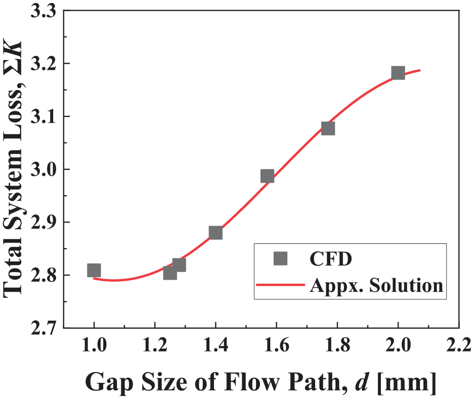
Total system loss depending on the flow path gap.
3.2 Parameter optimization
An aircraft’s landing performance is primarily determined by the shock strut efficiency (SSE), which is the most crucial design factor and describes the energy dissipation characteristics of the landing gear system (Currey, 1988). The SSE is the ratio of the energy dissipated in the MRLG to the maximum energy acting on the shock strut. The SSE is generally expressed in percentage units, and the SSE of a typical passive landing gear system shall not be less than 75%. It can be expressed as follows:
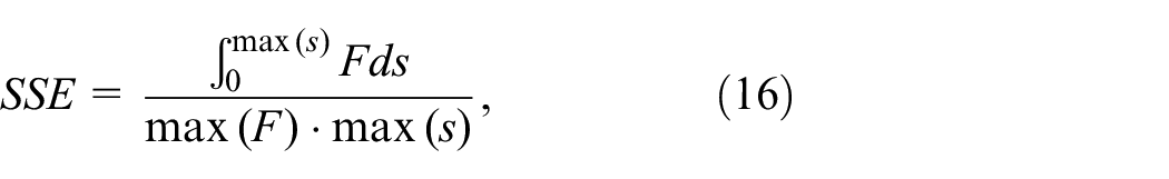
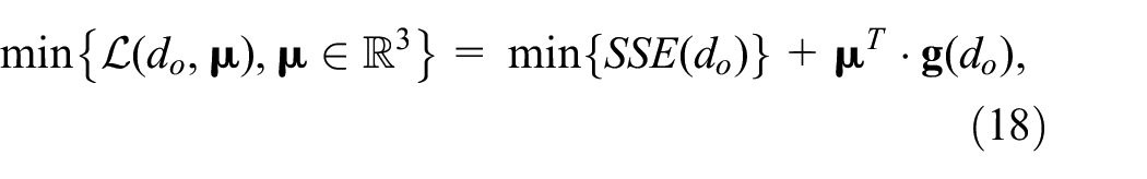
where F can be the main strut force or ground reaction Ft. “max” means the maximum value of the argument in the vector components. To secure the maximum controllable range of the SSE, the design parameters should be determined so that the off-state SSE is minimized under some constraint conditions. The sink speed, Vsink, for parameter optimization is set to the ultimate drop condition of 3.05 m/s in compliance with airworthiness standards (Federal Aviation Regulations, 1989). The optimal solution can be found through the following relation:

where
The SSE and do are set as a loss function and decisive variable,
where
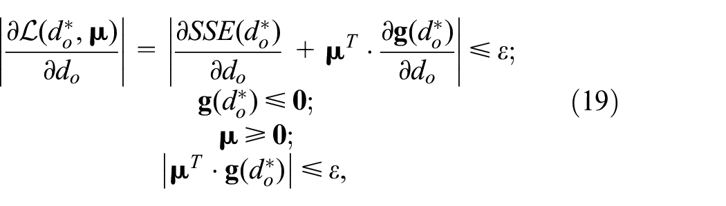
where the convergence error for the iteration stopping rule, ε, is set to 10−6. Finally, the optimal parameter
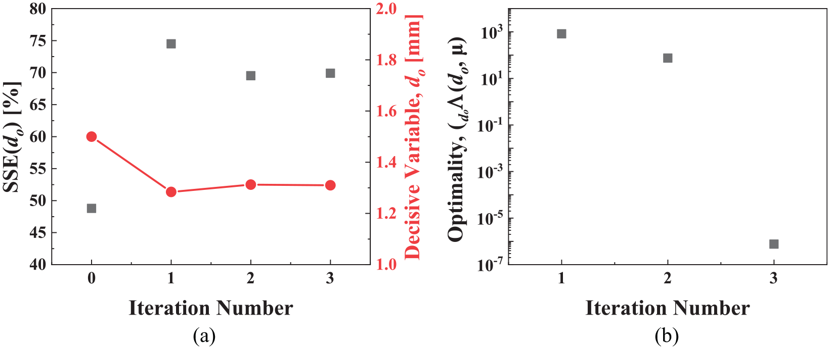
Parameter optimization results: (a) convergence for the SSE and do and (b) convergence of the optimality.
The yield stress for the input current can be calculated by simplifying equations (13) and (14) with the optimal parameter:

Furthermore, the entry length in the annular flow path is
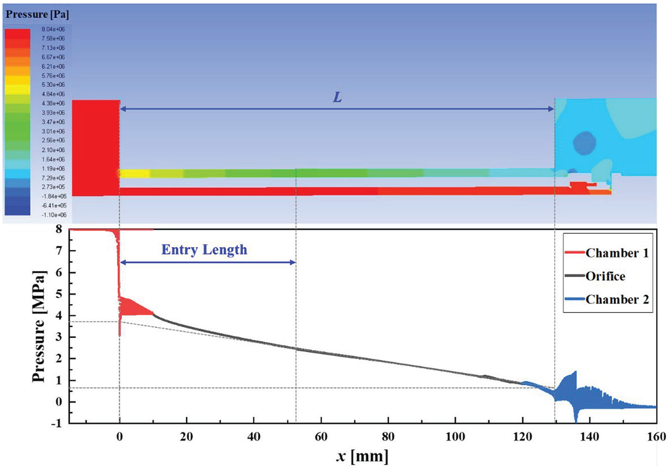
CFD result and pressure gradient for
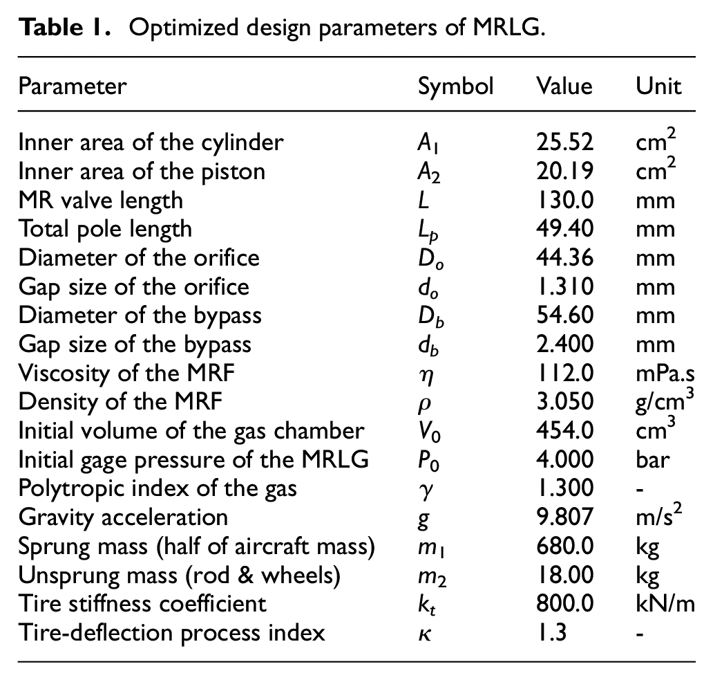
Optimized design parameters of MRLG.
4. Performance evaluation via drop test
All the components are manufactured, and the drop test is performed by mounting the MRLG onto the drop carriage to measure the responses and compare them with the simulated responses by adjusting the sprung mass, sink speed, and on-off states, respectively. In this work, the sink speed refers to the falling speed when the tire contacts the ground. The error between the measured and simulated data is analyzed with the root mean square (RMS) and coefficient of determination (R2), where the RMS means the square root of the mean square error of two data. R2 represents the variance ratio of the dependent variable; the closer to 1, the higher the correlation between the two data. The configuration of the drop carriage, dummy mass, sensors, DAQ (data acquisition) device, and sensor model names used in the experiment are shown in Figure 9.
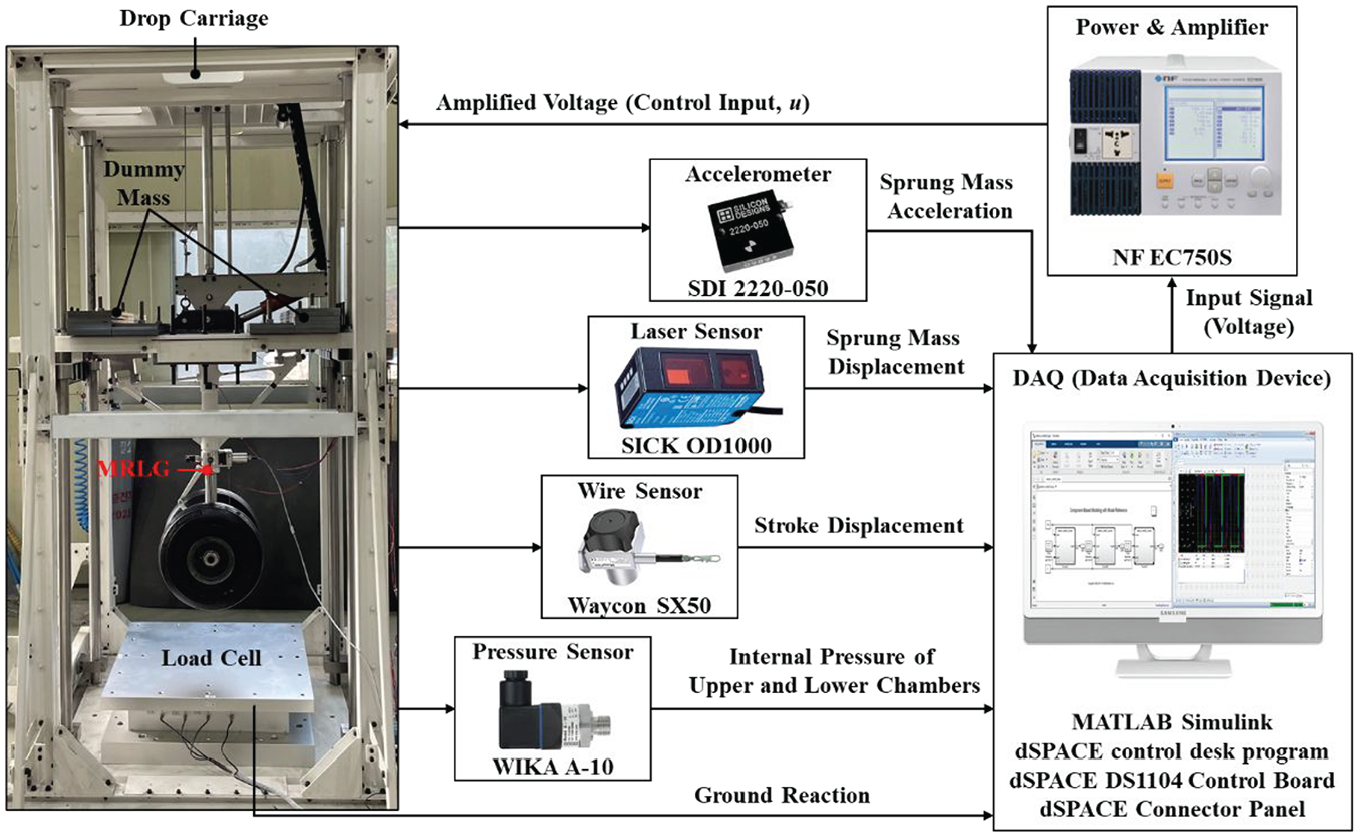
Vertical drop test configuration with MRLG.
Before proceeding with the authentic experiment, the pneumatic force and ground reaction are measured at the sink speed of 3.05 m/s, as presented in Figure 10. In the case of the pneumatic force, the simulated result based on equation (4) and measured data are compared. The results are shown in Figure 10(a), and the RMS and R2 between measured and simulated forces are 2.324 kN and 0.9217. In Figure 10(b), kt and κ of equation (3) are estimated through the measured ground reaction. As a result of the estimation, kt and κ are estimated to be 800 kN/m and 1.3; RMS and R2 are 2.820 kN and 0.8947, respectively.
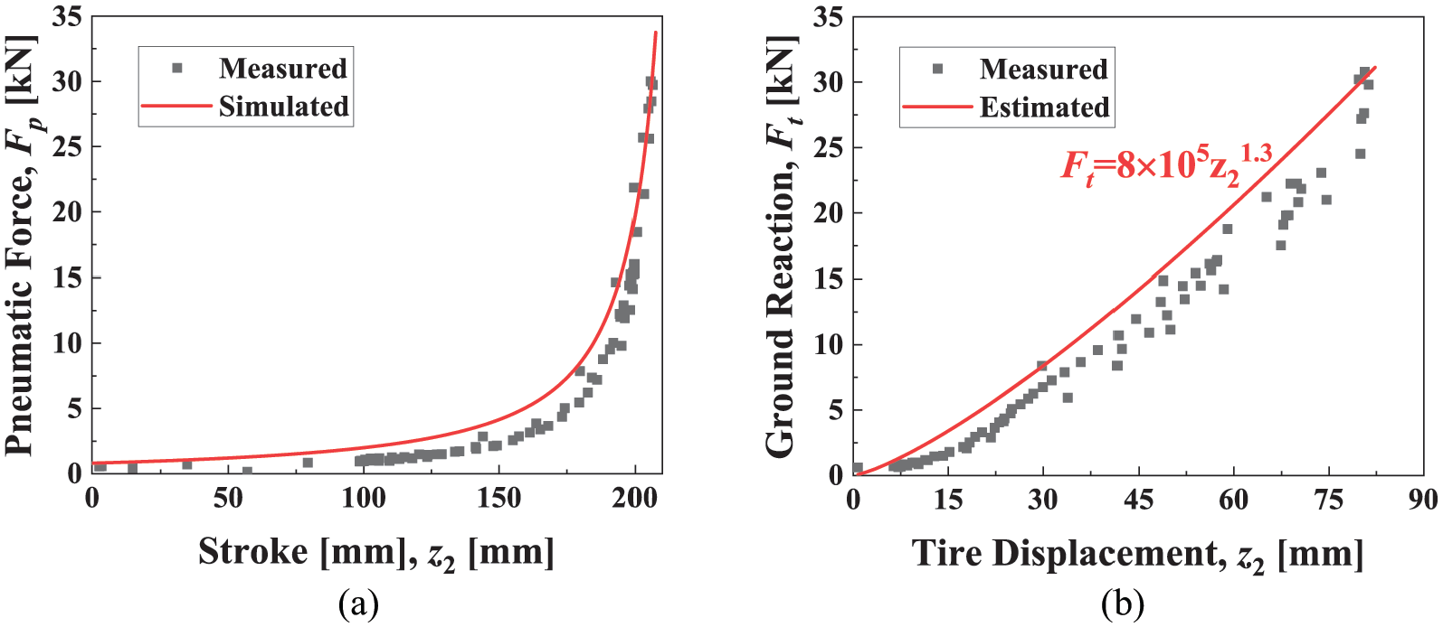
Comparison of tested and simulated results for Vsink = 3.05 m/s: (a) pneumatic force – stroke and (b) ground reaction – tire displacement.
The damping force is simulated and measured by applying the constant currents, 0, 0.5, 1.0, 1.5, and 2 A. As shown in Figure 11, the measured and simulated damping forces are compared. In the legend of the figure, applied constant currents are indicated, and there are the measured values on the left half side and the simulated values on the right half side represented with “_sim.” The field-dependent force can be calculated by subtracting the off-state damping force (0 A) from the on-state damping forces in the figure. From 0.5 to 2 A at the sink speed of 2 m/s, the simulated field-dependent force is 4.26, 8.42, 10.1, and 10.5 kN, and the measured field-dependent force is 2.85, 7.19, 10.29, and 11.45 kN, respectively.
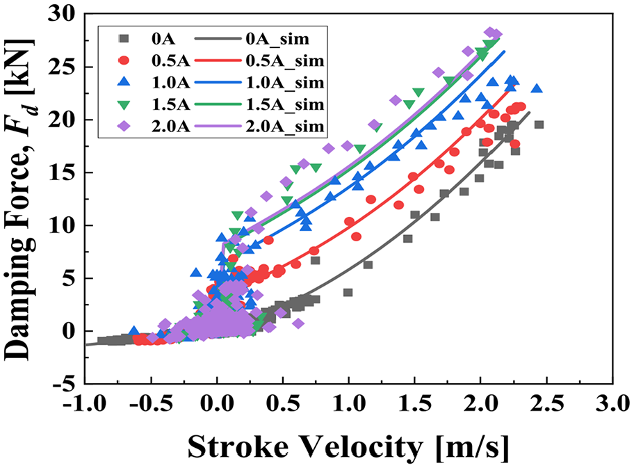
Comparison of tested and simulated damping force for velocity and current.
The drop tests for on-off states are progressed for the design targets, the sprung mass of 680 kg and sink speed of 3.05 m/s. Figure 12 shows the measured and simulated force-stroke curves and time-dependent jerk under the on-off states; One of the indexes to explain the boarding comfort is the jerk, of which a lower magnitude ensures a better boarding quality, and it can be derived by differentiating the accelerometer signal
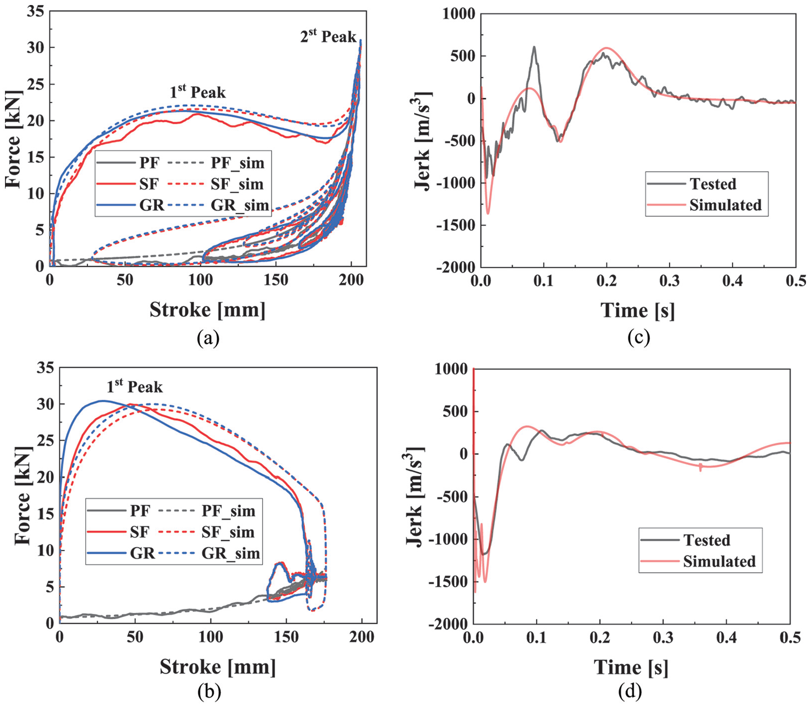
Measured and simulated drop testing results for m1 = 680 kg: (a) force – stroke (off-state), (b) force – stroke (I = 2 A), (c) jerk – time (off-state), and (d) jerk – time (I = 2 A).
Figure 13 shows the experimental results depending on the sprung mass and sink speed in off-state. Figure 13(a) to (c) visually shows the ground reaction changes over the stroke. As the upper mass or sink speed increases, the dissipated energy also increases; The energy can be calculated by integrating the ground reaction with the stroke. Moreover, the stroke speed and stroke increase simultaneously as the sink speed increases, and the first and second peaks of the force-stroke curve gradually stand out; The first peak and SSE seem relatively small because the low off-state damping force can be inferred from the slow sink speed; The off-state damping force and SSE increase at the fast sink speed since the maximum stroke is larger and the difference between the first and second peaks is smaller than at the slow sink speed. Table 2 summarizes the SSEs depending on the upper mass and speed, calculated from the force-stroke curves in the figure. Figure 13(d) to (f) shows the jerk estimated in the test. The figure shows that the jerk is dependent on the sink speed rather than the sprung mass; The magnitude of the jerk’s peak and valley increases as the speed increases. Table 2 shows the maximum magnitudes of the jerk valley and peak (Prime valley and peak) in conformity with the upper mass and sink speed.
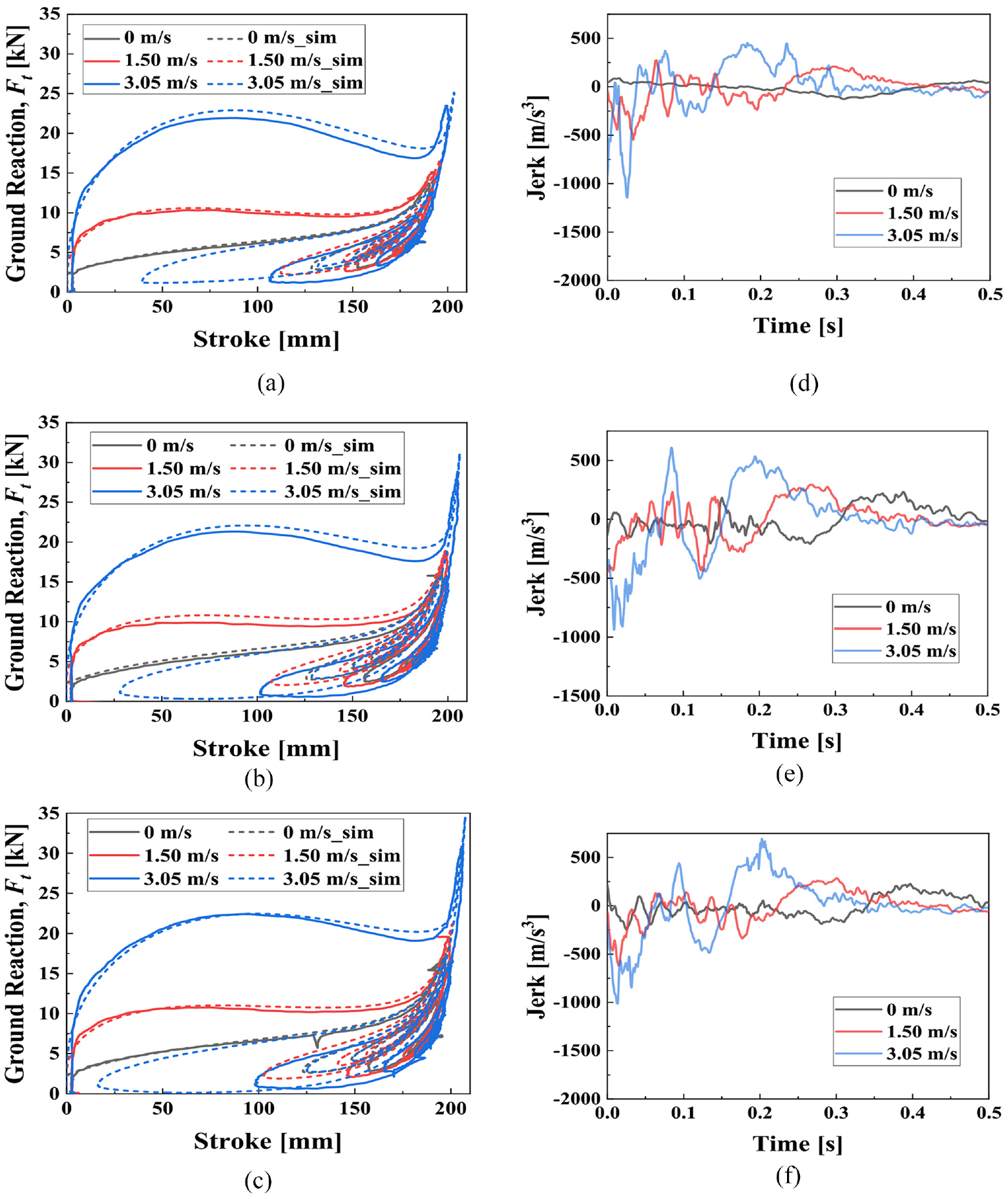
Measured and simulated results depending on the sink speed for off-state: (a) GR – stroke (m1 = 640 kg), (b) GR – stroke (m1 = 680 kg), (c) GR – stroke (m1 = 720 kg), (d) tested jerk – time (m1 = 640 kg), (e) tested jerk – time (m1 = 680 kg), and (f) tested jerk – time (m1 = 720 kg).
Drop test results of MRLG: SSE and jerk.
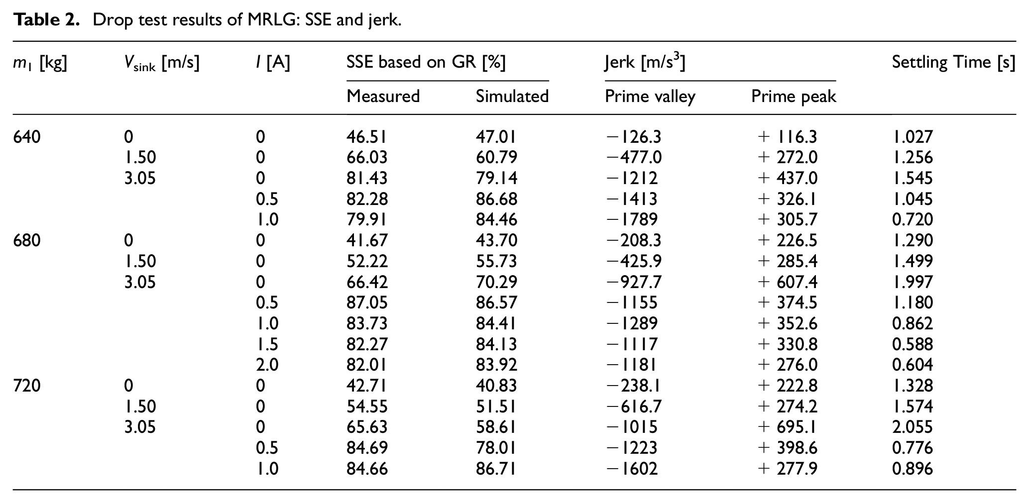
Figure 14 shows the force-stroke curve and jerk depending on the input current for each sprung mass. The damping force is proportional to the input current, as shown in Figure 14(a) to (c). Furthermore, the first peak for the damping force increases and the second peak for the pneumatic force decreases since the dissipated energy is the same when the upper mass and sink speed are fixed; The first and second peaks become similar with the input current of 0.5 A, and the first peak predominates at 1.0 A. Table 2 shows that the SSE can be highest at 0.5 A regardless of the sprung mass. It shows that the SSE can be maximized by minimizing the difference between the first and second peaks. In addition, it can be confirmed that the SSE can be varied depending on the input current. Furthermore, Table 2 indicates the SSEs to check the measured and simulated data error in Figures 13(a) to (c) and 14(a) to (c). The maximum differences between the measured and simulated SSEs within all drop test results are within 7%. Figure 14(d) to (f) presents the jerk’s tendency depending on the input current, and its prime valleys and peaks are summarized in Table 2. The magnitude of the prime valley tends to increase with increasing input current. The reason is that the increase in the input current and damping force decreases the stroke speed and the mechanical energy of the upper mass rapidly, which causes a sharp rise in the acceleration magnitude. In the figure, there is a prime peak after the prime valley, which is inversely proportional to the input current. Because the impulse to speed is reduced sufficiently depending on an increase of the dissipated energy before the prime peak, it is estimated that the prime peak decreases as the input current increases. Besides, the settling time is defined as the time required for the jerk to reach within 40 m/s3, corresponding to 2% of the maximum jerk. The results are shown in Table 2. The settling time is reduced as the sink speed and input current decrease, for both the sink speed and input current are related to the damping force. First, the mechanical energy is proportional to the sink speed squared, while the damping force is proportional to the stroke speed to the power of 1 and 2. Accordingly, a long settling time is required at the fast sink speed because it is difficult to dissipate energy sufficiently in the off-state. Second, because the input current and energy dissipation rate are proportional, a fast energy dissipation rate guarantees a short settling time.
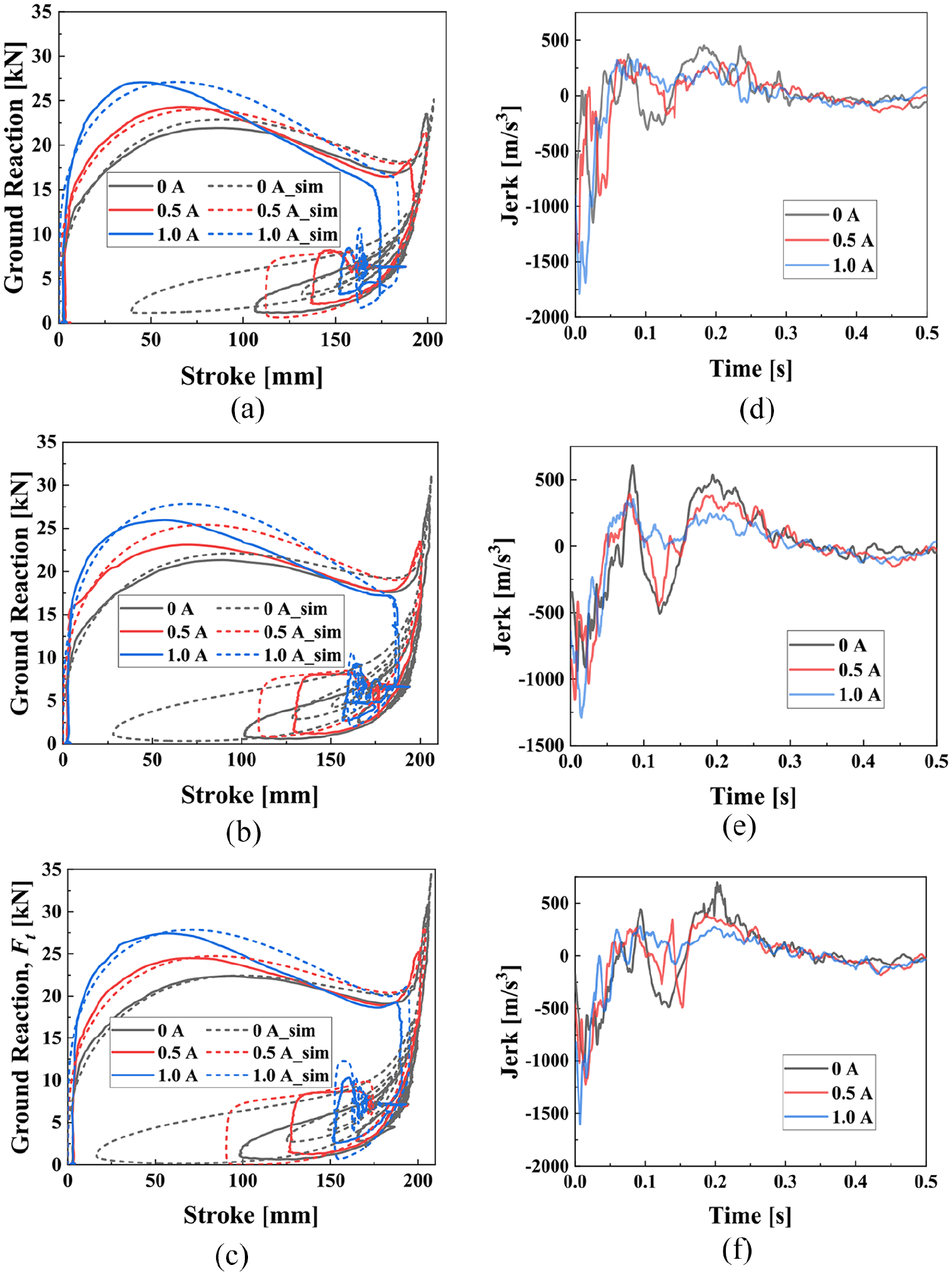
Measured and simulated results depending on current for Vsink = 3.05 m/s: (a) GR – stroke (m1 = 640 kg), (b) GR – stroke (m1 = 680 kg), (c) GR – stroke (m1 = 720 kg), (d) tested jerk – time (m1 = 640 kg), (e) tested jerk – time, and (m1 = 680 kg) (f) tested jerk – time (m1 = 720 kg).
5. Conclusion
The magnetorheological landing gear (MRLG) was designed, and parametric optimization was carried out in this study considering the major and minor losses. The pneumatic and damping forces were modeled mathematically suitable for fast stroke speed, and the magnetic intensity and total loss coefficient were determined by the magnetic analysis and computational fluid dynamics (CFD). Also, both the shock strut efficiency (SSE) and force controllability were optimized by setting the gap size of the flow path as a decisive variable. Next, a two-degrees-of-freedom vertical free-fall model was established with MRLG for the drop simulation. The simulation and the drop test were then performed to evaluate the landing performance and also validate the mathematical model. The results are summarized as follows. (i) SSEs for the strut force (SF) and ground reaction (GR) were compared by the test and simulation results. The force-stroke curves and SSEs for the SF were similar to those for the GR. (ii) The mathematical model of the MRLG was experimentally verified by SSE and jerk analysis. The errors between the measured and simulated SSEs are maintained within the maximum level of 7%. Moreover, the tested and simulated jerks were compared and confirmed to be similar based on the root mean square and coefficient of determination. (iii) SSE was changed depending on the sprung mass, sink speed, and input current. In terms of performance, the SSE can increase by adjusting the input current and reducing the difference between first and second peaks in the force-stroke curve. However, it was not possible to remove the valley between the first and second peaks by adjusting the constant input current. The landing performance may be rather deteriorated when the input current is applied too much. (iv) The jerk was analyzed for the sink speed and input current. The fast sink speed and high input current caused the jerk’s prime valley magnitude to enlarge. However, the jerk’s prime peak decreased depending on the increase of the input current, unlike the sink speed case. (v) The settling time was affected by the sink speed and input current. The fast sink speed increased the mechanical energy and slowed the settling time. On the other hand, the input current increased the energy dissipation rate to achieve a short settling time. Therefore, it is necessary to improve landing performance by designing a controller suitable for optimizing the SSE and settling time.
It is evident from this work, an appropriate control logic is absolutely required to reduce the prime valley and prime peak of the jerk, along with maximizing SSE. In this case, robust control strategies against modeling uncertainty, parameter variation and external disturbance are recommended to reflect practical environment conditions. It is finally remarked that an appropriate control logic will be implemented to the optimized MRLG to enhance the landing efficiency in the near future.
Footnotes
Declaration of conflicting interests
The authors declared no potential conflicts of interest with respect to the research, authorship, and/or publication of this article.
Funding
The authors disclosed receipt of the following financial support for the research, authorship, and/or publication of this article: This work was supported by the Technology Innovation Program (Intelligent landing gear with variable damping force for 1500 lb class) (10073291) funded by the Ministry of Trade, Industry & Energy (MOTIE, Korea).