
Abstract
This paper focuses on the performance improvement and evaluation of a novel flexible sandwich beam incorporated magnetorheological fluid porous fabric (MRF-PF). As a novel MR material, MRF-PF has been introduced, prepared, and measured to analyze the pre-yield property between complex shear modulus and magnetic fields. MRF-PF is used into the flexible sandwich beam as core layer. Pre-yield property with tunable stiffness is used to adjust the dynamic response. Then, a theoretical model is derived which can precisely describe the performance. Based on experimental results, sandwich beam incorporated MRF-PF has a good performance of controllability. When the magnetic field is applied into the free end, the natural frequency decreases with increasing the currents and filling ratio. In contrast, the frequency and amplitude increase when the clamped end is exposed to the magnetic fields. Comparing with other investigations, this proposed sandwich beam incorporated MRF-PF has a larger frequency range. The first and second natural frequency show the increases of 54.8% and 77.2%, respectively. The reduction of amplitude is closely related to the thickness of face plate. Therefore, the performance of the compound sandwich beam can be significantly improved by MRF-PF.
Keywords
1. Introduction
The concept of vibration controllability with intelligent materials within flexible adaptive beam is of significant interest in the last few decades. Owing to its well dynamic behaviors and variable stiffness of the flexible beam, it has been used in many critical engineering fields such as aircraft wing spars, tuned vibration absorbers, spacecraft isolation, bridge spans, and vibration sensors (Akhavan et al., 2019; Dyniewicz et al., 2015; Rajamohan et al., 2010b). With appropriate control of flexible adaptive beam, one of the most critical functions is reducing the undesirable vibration. As the core material with changeable mechanical properties, soft viscoelastic materials such as rubber, shape memory alloys (SMA), piezoelectric (PZT) material, and other intelligent fluids are stacked between two or more layers for improving the dynamic performance of the flexible adaptive beam. However, rubber is mainly used in passive vibration isolation system with a single working frequency band. Deformation restoring velocity of SMA and PZT is too slow to realize the real-time control. Hence, smart materials like electrorheological (ER) and magnetorheological (MR) materials are conveniently utilized into the flexible beams to realize vibration control with better performance (Dong et al., 2022). Moreover, MR fluid changes from liquid state to solid-like state reversely within only milliseconds under magnetic fields. Comparing with ER material, MR material is more suitable for high bandwidth control with minimum energy input via semi-active control (Choi et al., 2016). Especially, MR fluid and MR elastomer within the flexible beam are widely concerned and receive much attention in relative investigations.
The flexible beam incorporated MR fluid is proposed to improve vibration isolating performance (Rajamohan et al., 2010a; Sun et al., 2003). MR fluid in core layer provides rapid changes with stiffness and damping properties in real time by the external magnetic fields (Raja et al., 2014). With increasing the applied currents, the stiffness of the flexible beam changes quickly with a large range. A beam-like tunable vibration absorber filled by MR fluid was designed and the tunable range was from 106 to 149 Hz with an increase of 40% approximately (Hirunyapruk et al., 2010). Moreover, the natural frequency of MR cantilever sandwich beam had achieved the variation of 17.5% and vibration amplitude was decreased by 15.7 dB (Lara-Prieto et al., 2010). However, the settlement and leakage of MR fluid should be solved in the flexible beam which have limited its applications. In order to solve this problem, MR elastomer is utilized in the flexible beam. Particle chains are locked into the viscoelastic matrix with variable stiffness (Rasooli et al., 2020). The corresponding natural frequency of a developed vibration absorber with MR elastomer was tuned from 55 to 82 Hz with an increase of 47% (Deng et al., 2006). The flexible beam with MR elastomer had better vibration reduction than sandwich beam with viscoelastic core which was up to 30.63% (Nayak et al., 2011). What’s more, compression force between two layers can effectively increase the property of the sandwich beam (Szmidt et al., 2019). Hence, the flexible beam with MR elastomer core has a good performance in adjustable stiffness and vibration reduction. Compared with MR fluid, the variation of storage modulus with MR elastomer is less than MR fluid (Yang et al., 2019). It means that the range of adjustable stiffness of MR elastomer is lower than MR fluid.
For the sake of keeping the balance between dynamic performance and settlement of MR materials, a novel MR composite of MR fluid porous fabric (MRF-PF) with non-woven fabric is proposed. It is quite a new concept and very few investigations have been carried out in practical applications. MR fluid is stored in the matrix of non-woven fabric without any sealing mechanism. The internal porous network can effectively protect the magnetic particle chains (Nakano, 2011). Experimental results showed that the mechanical performance was improved by MRF-PF (Nakano et al., 2020). What’s more, MRF-PF was used in a variable inertial flywheel as the working medium. The tuning range of inertia was 27.5% (Dong et al., 2018). Based on these advantages, MRF-PF can be used into vehicle, sensor, and other semi-active control applications. According to the relative works, most research works are focus on the engineering applications to improve the output performance (Dong et al., 2018; Nakano, 2011; Nakano et al., 2020). Preparation and rheological properties of MRF-PF are not tested and further analyzed. The working principle with internal structure has not been reported in other works. Therefore, there is an urgent need to analyze the basic performance of MRF-PF for further applications.
Furthermore, the dynamic properties of MRF-PF in the flexible adaptive beam have not been found and analyzed in other research works. MRF-PF is consist of the matrix and MR fluid. This matrix is the three-dimensional porous structure which is formed by the thinner fiber. Comparing with other MR materials such as MR elastomer and foam (Ge et al., 2015), the absorbed MR fluid can flow freely inside the matrix. Internal fibers can effectively hold the particle chains along magnetic field to enhance the stiffness of the sandwich beam. The shear strength and pre-yield property were improved greatly (Mistik et al., 2012). These properties are totally different from other MR materials. Considering these unique properties of core layer in flexible beam, dynamic properties become different which has not been reported. Therefore, the sandwich beam with MRF-PF should be further analyzed with dynamic performance.
Based on the above motivations, the main contributions include rheological property of MRF-PF and performance evaluation of this novel sandwich beam. The dynamic properties of flexible sandwich beam incorporated MRF-PF are measured and analyzed firstly in this paper. MRF-PF is fabricated and tested as the core layer of the flexible adaptive beam. The dynamic properties of MRF-PF in pre-yield region are analyzed with complex shear modulus. Due to the strong representation of the cantilever which can be utilized to analyze other sandwich beams, a theoretical model of cantilever sandwich beam is derived considering the filling ratio and other factors. The dynamic performance of this flexible sandwich beam is analyzed and evaluated comparatively with other conventional MR materials. The remaining sections of this paper are listed as follows. The fabrication and material characteristics of MRF-PF and flexible adaptive beam are shown in section 2. Considering the properties and filling ratio of MRF-PF, theoretical model is derived in section 3. The finite element analysis (FEA) and comparative experiments have been discussed in section 4. Conclusion is shown in section 5.
2. Fabrication and material properties
In this section, this novel MR composite of MRF-PF was prepared and tested. The detailed preparation procedures of MRF-PF and the compound flexible sandwich beam had been introduced.
2.1. Preparation of MRF-PF
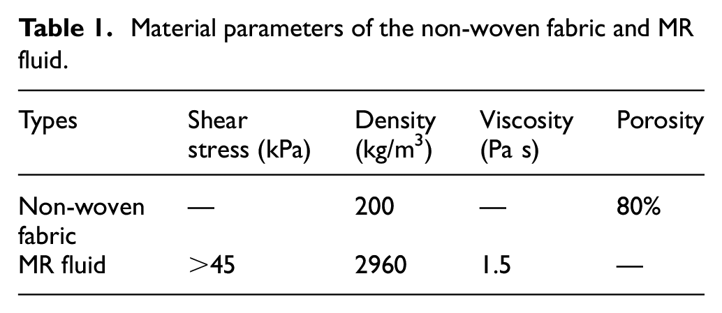
As a MR composite, MRF-PF consists of the non-woven fabric and MR fluid. The non-woven fabric was purchased from Changtai Non-woven fabric Co., Ltd. (Shenzhen, China). The commercial MR fluid (type MRF-G28) was obtained from Chongqing Materials Research Institute Co., Ltd. (Chongqing, China) with the volume fraction of 28%. Other additives of acetone, ethanol solution, and deionized water were from Aladdin Chemistry Co., Ltd. (Shanghai, China). All reagents were of analytical level which require no further purification. Material parameters of main raw materials were listed in Table 1.
Material parameters of the non-woven fabric and MR fluid.
The preparation of MRF-PF includes two steps which are shown in Figure 1. In the first step, matrix of non-woven fabric was clipped with a specific diameter and cleaned by acetone and 95% ethanol solution. The treated samples were dried at 80°C for 1 h. And then, the cleaned non-woven fabric can be obtained for further treatments. In the second step, MR fluid was stored into the non-woven fabric. The cleaned non-woven fabric was immersed by the commercial MR fluid of MRF-G28 with ultrasonic dispersion for 1 h. This treatment can make non-woven fabric absorb MR fluid effectively. Next, the mixed non-woven fabric was located vertically for 1 h to separate the extra MR fluid. In order to ensure the uniformity of the dispersion, these two treatments were repeated with three times. Therefore, the uniformly dispersed MRF-PF can be obtained which was shown in Figure 1.
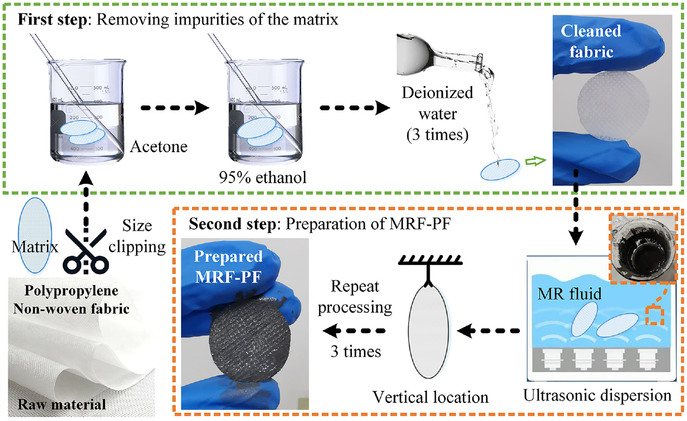
The preparation and treated sample of MRF-PF.
2.2. Performance test of MRF-PF
In order to further analyze the performance of MRF-PF, the rheological property was measured by the commercial rheometer (type MCR 302) of Anton Paar Co., Ltd. (Austria). MRF-PF was fixed on the testing base by alcohol glue (Ausbond Co., Ltd., Shenzhen). The matrix was fixed and performance of MRF-PF can be measured precisely. These experimental set-ups were shown in Figure 2.
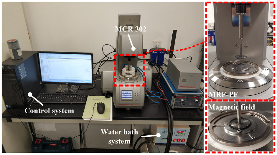
Experimental set-ups to measure the rheological properties of MRF-PF.
Dynamic shear modulus of MRF-PF was measured by the dynamic oscillatory mode. This experiment consists of two parts. The first experiment was operated on the shear strain sweep mode. The boundary conditions between linear viscoelastic (LVE) range and other ranges of MRF-PF can be measured by this test. The shear strain changed from 10−2 to 102 s−1 at the specific frequency of 10 Hz. The range of magnetic field was 0–0.6 T with a step of 0.3 T. Based on the variations of storage modulus (G′), LVE range of MRF-PF can be obtained. Based on the measured LVE range, experiments under magnetic field sweep mode were carried out with various magnetic fields. In this experiment, the specific shear strain was in LVE range and the excitation frequency was fixed at 10 Hz. The non-linear relationship can be obtained between dynamic modulus and magnetic field intensity. Moreover, to ensure the accuracy and repeatability of the measured results, the repeated tests of MRF-PF were conducted for three times under each excitation. The average values of three tested results were used to further performance evaluation of MRF-PF.
The measured results of storage and loss moduli under shear strain sweep mode have been listed in Figure 3. The G′ at various magnetic fields is shown in Figure 3. It can be observed that G′ keeps constant at small shear strain. This region is the so-called LVE range. With increasing the magnetic field, LVE range increases gradually and the flow point of MRF-PF increases simultaneously. These effects are determined by the stronger particle chains which can be formed by a larger magnetic field.
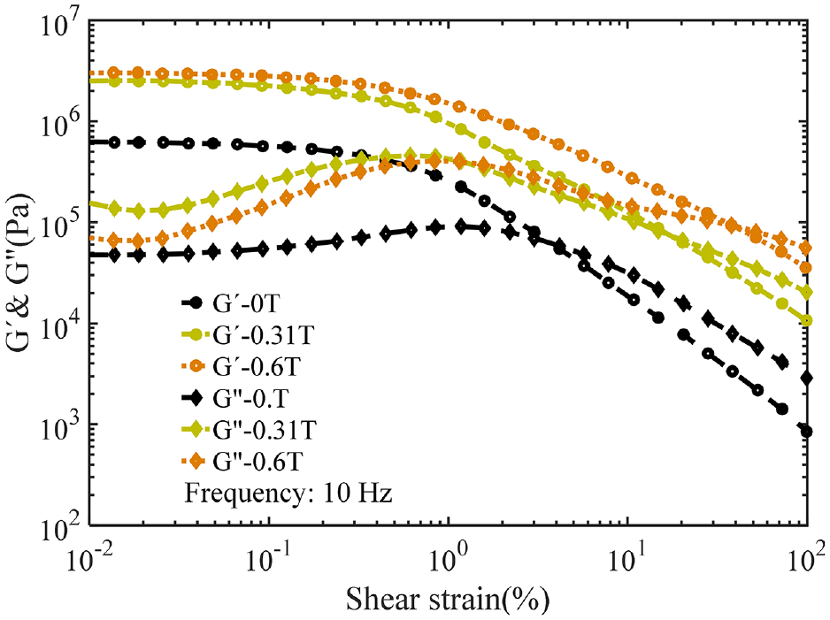
Storage and loss moduli of MRF-PF at shear strain sweep mode.
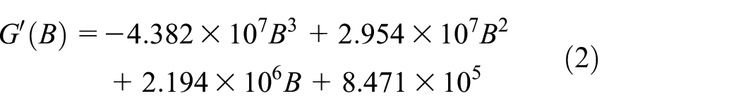
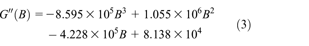
Based on the measured results under shear strain sweep mode, LVE range of MRF-PF has been obtained. Then, the shear strain is fixed at 0.01% in magnetic field sweep mode. The variations of G′ and loss modulus G″ have been shown in equations (1) and (2). Under small shear strain, MRF-PF works in pre-yield region. G′ increases rapidly with the increase of the applied magnetic fields. It means that MRF-PF becomes harder with a larger stiffness. However, G′ and G″ decrease significantly with the increase of the shear strain at large shear strain. And MRF-PF works in post-yield region at this condition.
By fitting the experimental results, the complex shear modulus of MRF-PF can be expressed as

The corresponding storage modulus G′ and loss modulus G″ with magnetic field strength B can be shown as
2.3. Fabrication of the sandwich beam
In order to analyze dynamic performance of the proposed flexible sandwich beam, the three-layered sandwich beam incorporated MRF-PF has been proposed and fabricated. In the fabrication of the proposed sandwich beam, aluminum alloy (6061) has been used as face plate due to the lower permeability which is equal to unity. When the external magnetic field passes through the sandwich beam, the distributions of magnetic field will not be affected.
The flexible sandwich beam incorporated MRF-PF is fabricated by three steps. Firstly, the gasket of aluminum alloy is glued to the lower face plate by the AB glue (EP05, Ausbond, America). The parallel face plate is 240 mm long and the width is 40 mm. And then, MRF-PFs with special shape are glued to the face plate to fill the gap. Finally, the upper face plate is fixed at the corresponding gasket. All sandwich beams have the same gap width of 1 mm. The fabrications are shown in Figure 4. In this sandwich beam incorporated MRF-PF, there is no sealing mechanism to avoid leakage of MR fluid. MR fluid is stored into the porous matrix.
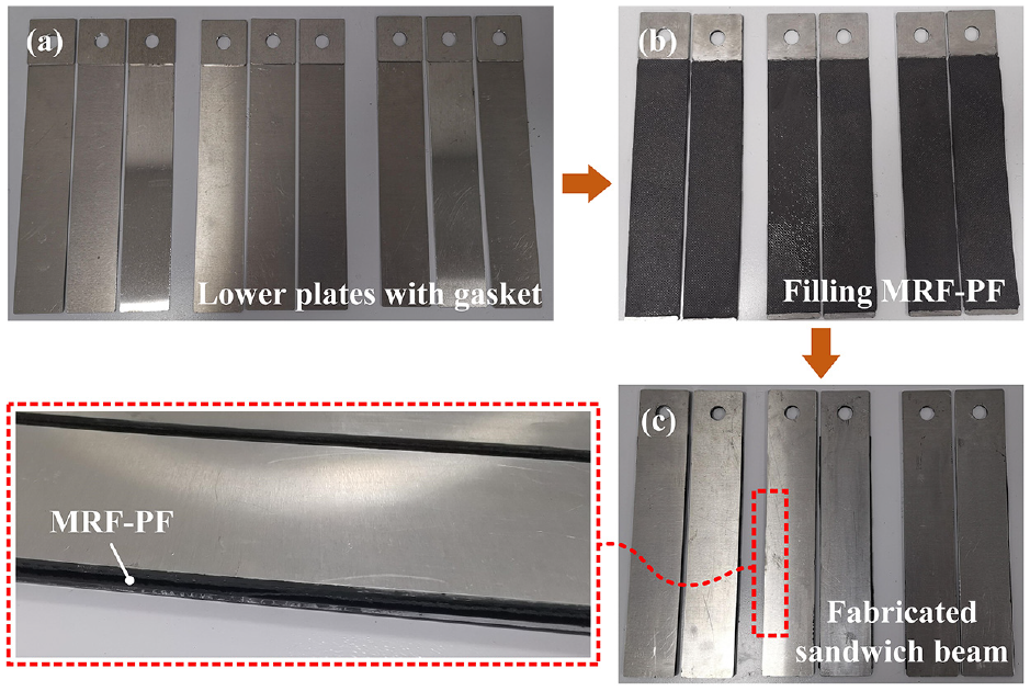
Fabrication of the sandwich beam incorporated MRF-PF: (a) plate fixation, (b) filling method, and (c) whole assembly.
3. Theoretical analysis
In this section, dynamic behavior of the proposed sandwich beam incorporated MRF-PF has been derived and modeled. These assumptions considered into this model are listed as follows. (1) Deformation of face plates can be analyzed by Euler-Bernoulli theory. (2) The link between plates are non-detachable. (3) The transverse displacement is the same with different layers. (4) There is no normal stress in MRF-PF and no shear strain in the plates.
The mechanical configurations are shown in Figure 5. u1, u2, u3 are axial displacements with upper plate, MRF-PF and lower plate, respectively. w2 is the transverse displacement of MRF-PF. The upper and lower plates are arranged symmetrically. h1, h2, and h3 are thicknesses of two plates and core layer, respectively.
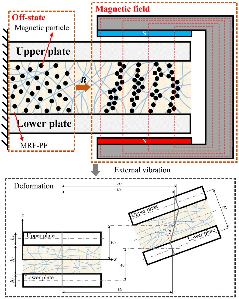
Deformation of the proposed sandwich beam incorporated MRF-PF.
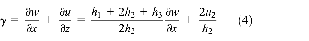
The shear strain in MRF-PF can be shown as
Based on the finite element (FE) method, this sandwich beam is divided into two nodes with six degrees of freedom (DOF). The nodal DOF vector is given by

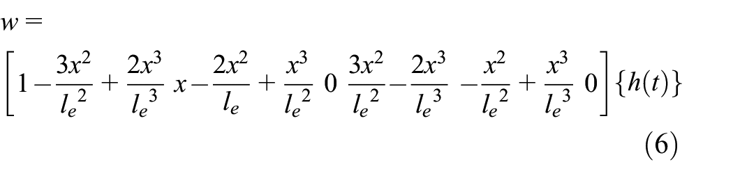
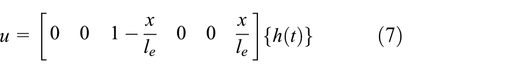
According to previous investigations, the displacements and shear strain along various directions of the proposed sandwich beam are shown as
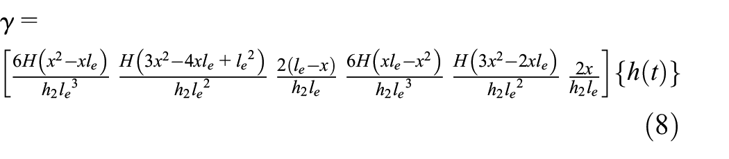
Where le is the length of the sandwich beam. H is equal to (h1 + 2h2 + h3)/2. The total strain and kinetic energies of this sandwich beam are listed with each plates. The kinetic energy consists two parts: upper and lower plates and cored material of MRF-PF. These are given respectively by
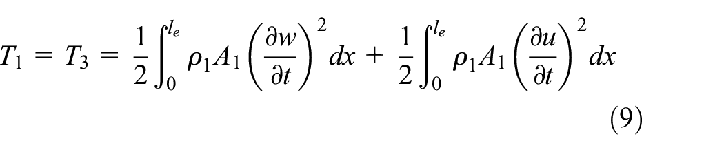
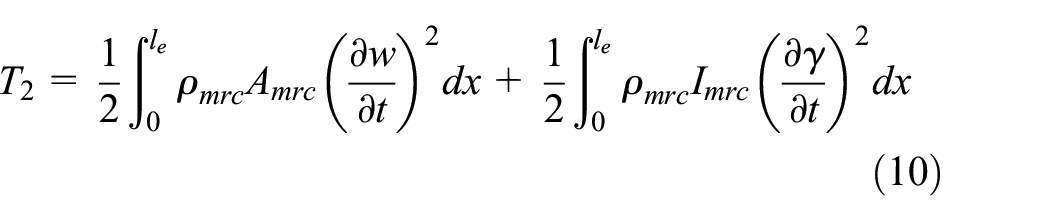
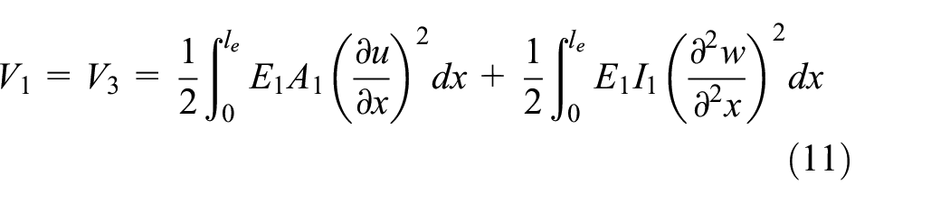
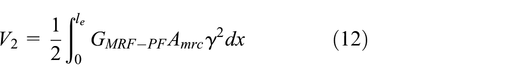
Where ρ1 and ρmrc are density of upper plate and core layer, respectively. A1, Amrc are the corresponding section area, respectively. I1, Imrc are the torsional moment of upper plate and core layer, respectively. The strain energy which includes two parts also can be expressed as
What’s more, considering the excitation position and filling ratio, the filling ratio is calculated by changing the effective area Amrc. The excitation position is considered by adjusting stiffness by multi-step integral. Therefore, matrixes of equivalent stiffness and mass can be derived by the kinetic energy and strain energy, respectively.
These matrixes of equivalent mass Me can be shown as

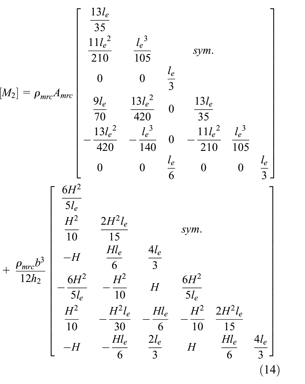
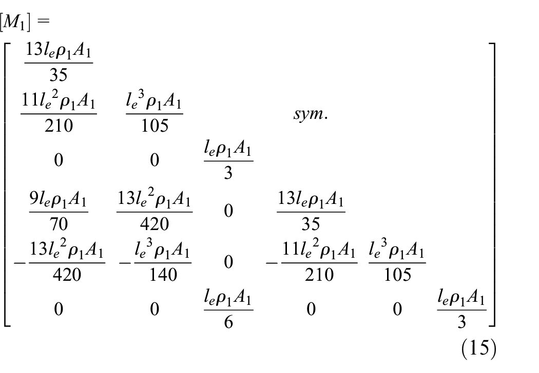
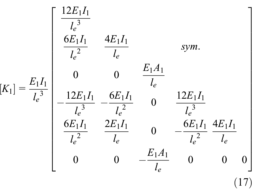
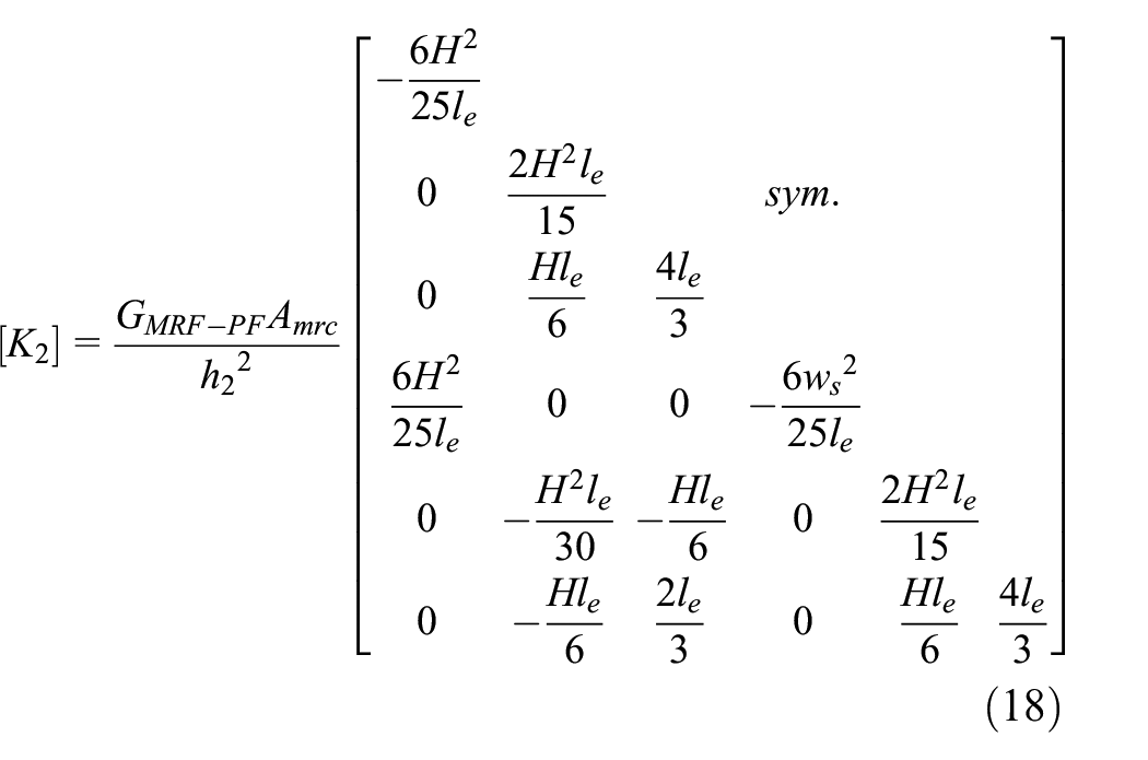
Where b is the width of the plate. These matrixes of equivalent stiffness Ke can be shown as equation (16). K1, K2, K3 are stiffness of upper plate, core layer, and lower plate, respectively. E1 is the young’s modulus of plate.

The damping property of the cantilever beam is shown as
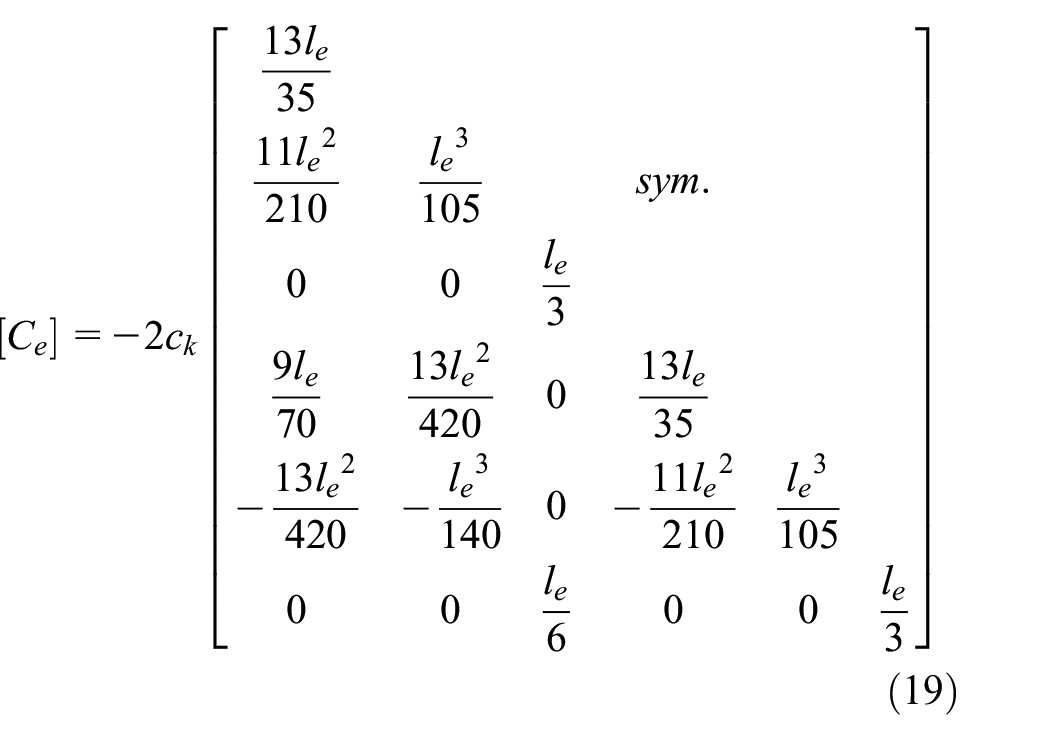
Where ck is the damping coefficient of the aluminum beam. Based on the Hamilton’s principle, the matrix equation of motion for this sandwich beam is shown as

Therefore, the dynamic property of natural frequency can be obtained by above equation.
4. Experiments and discussion
4.1. Finite element analysis
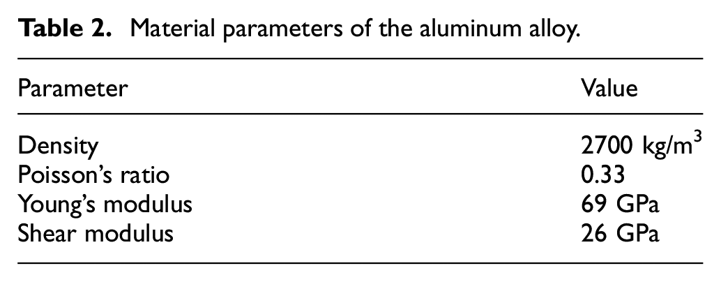
In order to further analyze the property of the sandwich beam with MRF-PF, the finite element analysis (FEA) has been carried out to analyze the dynamic properties of the sandwich beam. The fundamental parameters with the proposed sandwich beam are listed in Tables 1 and 2.
Material parameters of the aluminum alloy.
The software of ANSYS 15.0 has been adopted in the simulation. The sandwich beam with the thickness of 1 mm and working width of 1 mm has been analyzed in FEA. The three-dimensional model of this sandwich beam is divided by adaptive mesh division. Meanwhile, the convergence of the FEA result has been considered into the simulation to ensure precise. The modal vibration types with the first three stages are shown in Figure 6.
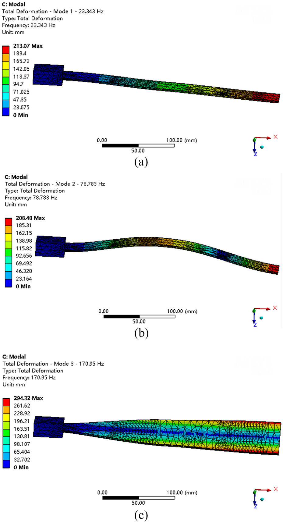
Modal vibration types in first three stages of the sandwich beam: (a) first order, (b) second order, and (c) third order.
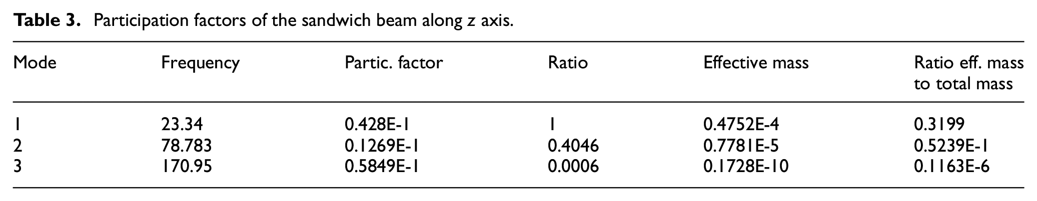
According to the FEA results, the first natural frequency of the sandwich beam is 23.34 Hz with the displacement along z axis. The modal vibration type in the second stage is the s-type along the same axis. What’s more, the effective modal mass can be used to identify the dominant vibration mode which has been listed in Table 3. The first and second natural frequencies contribute to 80.3% and 13.1% of the effective modal mass, respectively. Therefore, the first two modes are the main vibration mode and other higher-order modes of the sandwich beam can be ignored. Hence, the first two modes of this sandwich beam have been analyzed in the further experiments.
Participation factors of the sandwich beam along z axis.
4.2. Experimental test
The output performance of the sandwich beam with MRF-PF has been analyzed qualitatively and quantitatively by comparative experiments. In order to analyze the effects of main factors on dynamic properties deeply, the thickness of the sandwich beam, applied current, filling ratio, and excitation position have been investigated and discussed. The experimental set-ups of the sandwich beam are shown in Figure 7. For application of the forced vibrations, the commercial vibration exciter (JZK-50, Sinocera Piezotronics, Inc., China) has been adopted with the peak sine force of 500 N and maximum displacement of 15 mm. The exciter is driven by power amplifier and controlled by the dSPACE controller. The DC power device (E3631A & U8032A, Agilent, America) is used to supply the regular current for magnetic field generators which ranges from 0 to 1 A. Due to the different types with two power devices, the maximum currents are 1 and 0.5 A, respectively. The vibrational acceleration signals are measured by the accelerometer (4382, Bruel & Kjar, Denmark). Two accelerometers have been fixed at the free end and clamped end. Acceleration signals are collected by the corresponding dynamic signal analyzer.
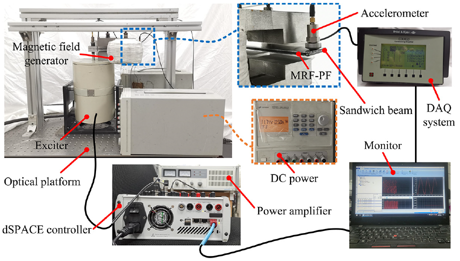
Experimental set-ups with the sandwich beam incorporated MRF-PF.
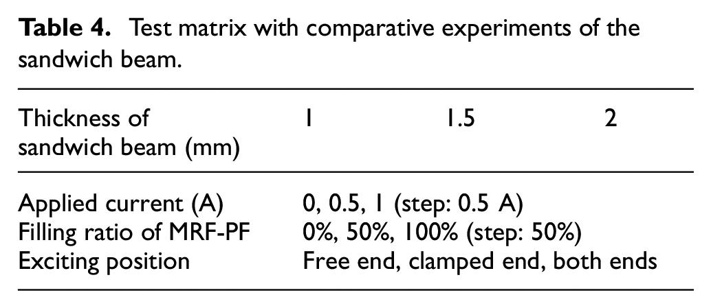
In order to analyze the output performance of the flexible adaptive beam systematically, comparative experiments with different factors were carried out. All performance experiments with the test matrix are listed in Table 4. The thickness of the sandwich beam ranges from 1 to 2 mm. What’s more, under the same thickness, the applied current, filling ratio, and exciting position have been analyzed separately. Due to power limitation of the DC power device, the resistance of the self-made magnetic field generator is 60 Ω and the maximum current are set at 1 and 0.5 A with different types of power device, respectively. The filling ratio and exciting position are considered into comparisons.
Test matrix with comparative experiments of the sandwich beam.
These comparatively experiments consist of two parts. The first part is the performance test of the sandwich beam without MRF-PF. These sandwich beams with different thickness are tested. In the second part, sandwich beams with MRF-PF are measured under various excitations. The mechanical properties of sandwich beam with MRF-PF can be analyzed deeply.
4.3. Discussion
In this section, the vibration responses in terms of natural frequency and acceleration are comparatively analyzed under different excitations.
4.3.1. Characteristic of thickness
The mechanical properties of the proposed sandwich beam with various thickness have been analyzed. First, the acceleration response in frequency-domain of the sandwich beam without MRF-PF is shown in Figure 8. It can be observed that the first two order frequencies of the sandwich beam increase with increasing the thickness. The first order natural frequencies are 11.29 and 17.23 Hz with the thicknesses of 1 and 2 mm, respectively. It shows 52.6% increase with the increase of the thickness. What’s more, there is a small resonance peak near the second natural frequency. This effect may be caused by the accelerometer. It will absorb the resonance energy to form a small peak near the second natural frequency. Therefore, this small resonance peak can be ignored. The second natural frequency of the sandwich beam changes from 91 to 148.5 Hz with an increase of 63.2%. It means that the stiffness of the sandwich beam increases dramatically with the increase of the thickness. The corresponding acceleration amplitude increases simultaneously and vibration of the sandwich beam becomes more intensified.
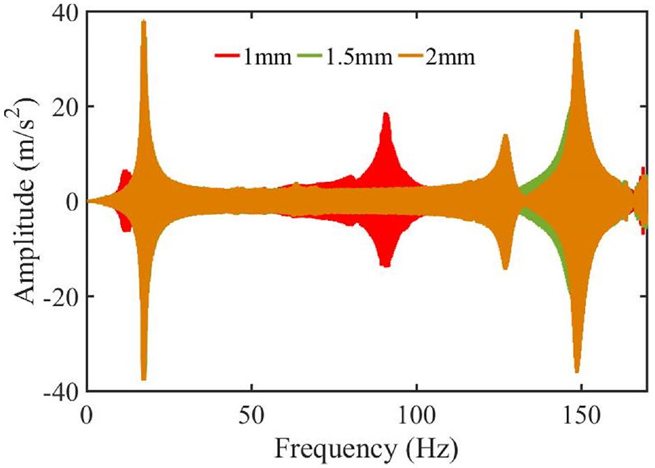
Frequency response of the sandwich beam without MRF-PF.
The vibration has been further analyzed by the acceleration transmissibility which is shown in Figure 9. With increasing the thickness of the plate, the acceleration transmissibility increases rapidly, especially in the first natural frequency. These values of the transmissibility are 4.84, 22.12, and 23.47 with various thicknesses in the first order mode, respectively. It has been increased by 384.9%. It means that the vibration of the sandwich beam becomes more serious at resonance frequencies. These increases are caused by the variation of the stiffness property. The sandwich beam without MRF-PF behaves a harder state.
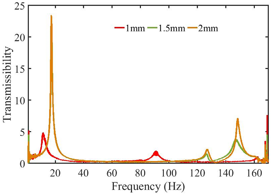
Acceleration transmissibility of the sandwich beam without MRF-PF.
When MRF-PF is filled into the middle gap of the sandwich beam, the performance is different from conventional sandwich beam. When the filling ratio is 50%, the frequency responses with different currents have been shown in Figure 10. When the sandwich beam is excited at off state, the natural frequency and acceleration amplitude decrease with increasing the thickness at the first resonance frequency. It ranges from 15.12 to 10.57 Hz which shows a decrease of 30.1%. The second natural frequency decreases rapidly, then increases slowly. The acceleration amplitude increases firstly and decreases with increasing the thickness. This phenomenon is closely related to MRF-PF. When the sandwich beam is partly filled by MRF-PF, the effective mass of the compound sandwich beam becomes large and MR fluid has been limited into the matrix. The damping property of MR fluid is introduced into the compound sandwich beam. Therefore, the first natural frequency decreases continuously. At the second resonance peak, the stiffness has greater impact on the frequency shift. The second resonance frequency increases slowly due to the higher thickness of the sandwich beam.
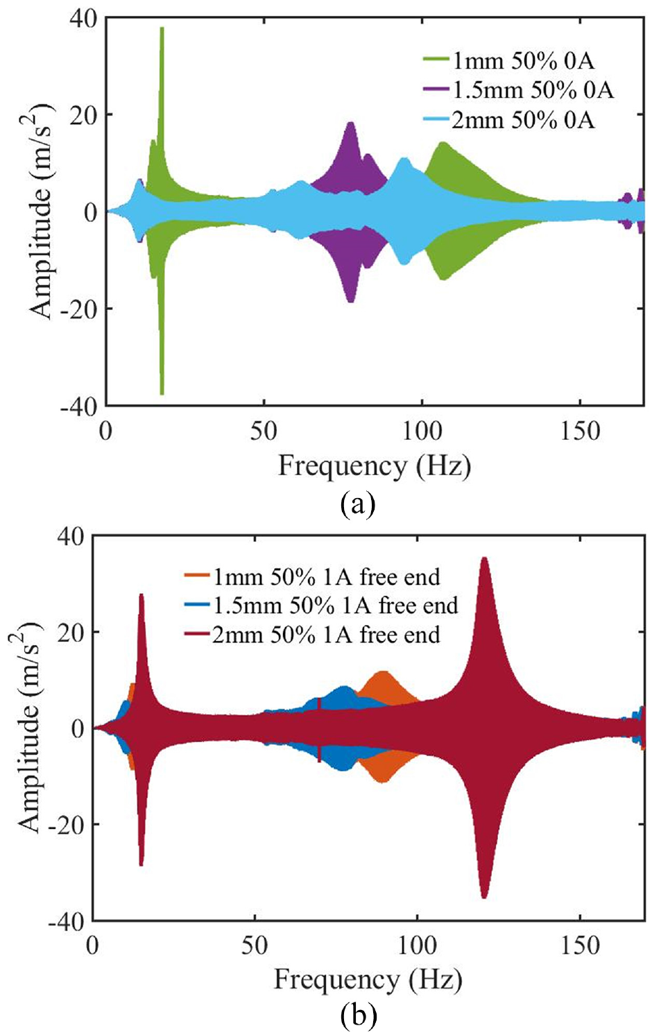
Frequency response of the sandwich beam with the filling ratio of 50%: (a) 0 A and (b) 1 A and free end.
The performance becomes different while the current is applied into the free end. With the increase of the thickness, the frequency responses at such excitations are shown in Figure 10(b). The first two natural frequencies decrease at the beginning, and then increase rapidly. The first natural frequencies are 12.25, 10.37, and 15.05 Hz with various thicknesses, respectively. The decrease effect is determined by the current excitation and damping effect of MRF-PF. When the magnetic field is applied into the free end, the natural frequency will decrease and vibration can be improved. With increasing the thickness, the stiffness of this sandwich beam increases greatly. MRF-PF behaves as the solid-like state and it’s hard to be sheared. The stiffness property plays a significant role in output performance comparing with the damping effect. The stiffness of the sandwich beam increases rapidly and the natural frequency increases simultaneously.
The acceleration transmissibility under such excitations has been shown in Figure 11. At this condition of the filling ratio of 50% without currents, the transmissibility decreases gradually with increasing the thickness at the first resonance frequency. It changes from 8.1 to 4.99 with a decrease of 38.3%. This effect is caused by the damping property of MRF-PF. At the second resonance point, the transmissibility increases in small range, and then decreases slowly. This variation is possible due to the stiffness which is the major factor at the second mode. What’s more, when the current is applied, the transmissibility decreases until the thickness is 1.5 mm. Under this condition, the damping property of MRF-PF can effectively improve the vibration. With the further increase of the thickness. The transmissibility increases rapidly and vibration becomes more serious. This increase is determined by the higher stiffness with a larger thickness of the sandwich beam.
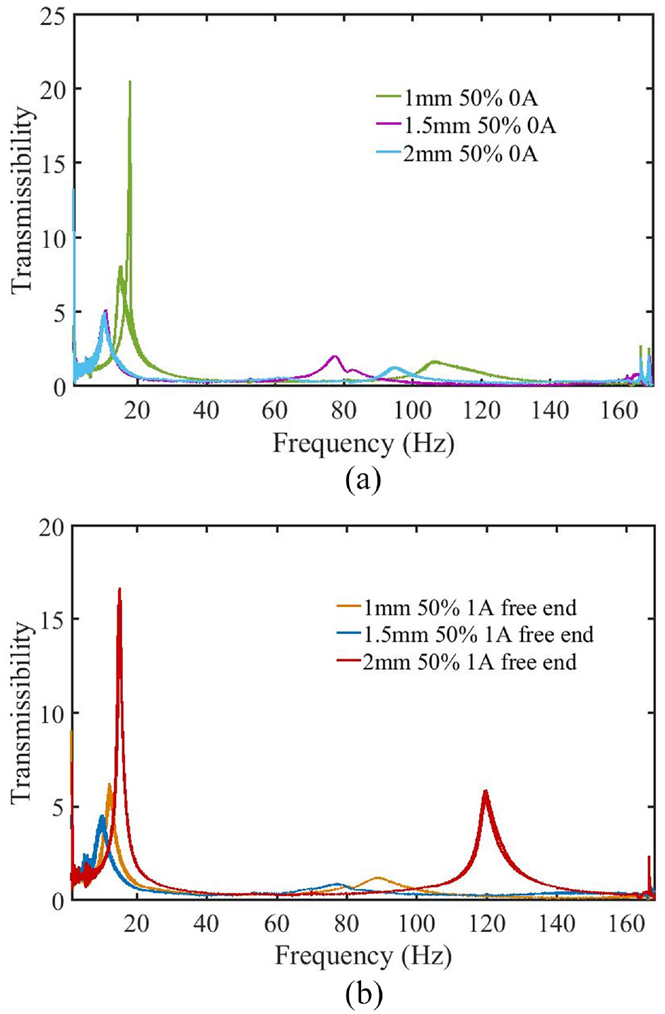
Acceleration transmissibility under various excitations: (a) 0 A and filling ratio of 50% and (b) 1 A and free end and filling ratio of 50%.
Therefore, the thickness directly affects the performance of the flexible sandwich beam. The natural frequency and acceleration transmissibility increase with increasing the thickness. However, MRF-PF can effectively improve the vibration isolation effect by the damping property.
4.3.2. Characteristic of filling ratio
As a novel compound sandwich beam with MRF-PF, filling ratio of MRF-PF has been further analyzed. The vibration responses in frequency-domain with different filling ratios have been shown in Figure 12. Experimental results show that the first two natural frequencies decrease rapidly with the increase of the filling ratio. When the applied current is 0 A, the first natural frequencies range from 17.37 to 10.1 Hz with a decrease of 41.9%. The second natural frequencies are 147.8, 77.1, and 70.28 Hz with different filling ratios, respectively. It shows a decrease of 52.4%. It proves that the filling ratio can effectively affect the dynamic property of the compound sandwich beam. The control bandwidth is enlarged greatly by filling MRF-PF. This effect is determined by the effective mass of MRF-PF. With increasing the filling ratio, the system damping and effective mass increase which lead to the variation of the natural frequency.
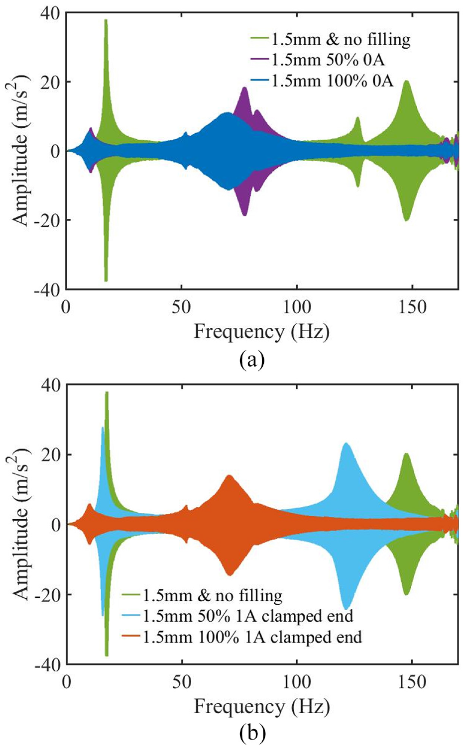
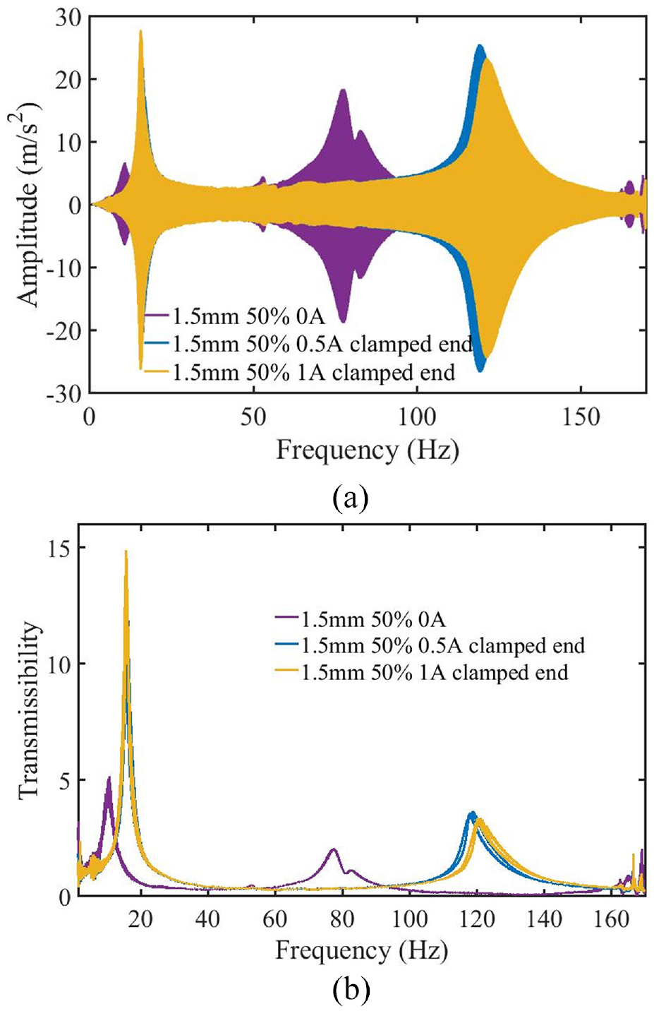
Frequency response at the thickness of 1.5 mm with different filling ratios: (a) 0 A and (b) 1 A and clamped end.
When the current of 1 A is applied into the clamped end, the first natural frequencies are 17.37, 15.72, and 10.25 Hz with various filling ratios, respectively. The second natural frequencies are 147.8, 121.5, and 71.19 Hz with various configurations, respectively. Comparing to the frequency response without currents, the first two natural frequencies increase gradually. The main reason is the excitation of the applied current. When the current is applied into the clamped end, MR fluid of MRF-PF behaves as the solid-like state. The local stiffness in the clamped end increases significantly. The vibration response becomes serious and frequency shift effect decreases.
Considering the influence of filling ratio, the acceleration transmissibility is shown in Figure 13. It is demonstrated that the transmissibility decreases significantly with the increase of the filling ratio. These values of the first resonance frequency range from 22.12 to 4.78 with a decrease of 78.3% under the condition without currents. The vibration has been improved greatly by filling MRF-PF. This improvement is determined by the damping property of MRF-PF. With increasing the filling ratio, more MR fluid has taken part in the vibration isolation of the sandwich beam. The damping property of the compound sandwich beam increases significantly.
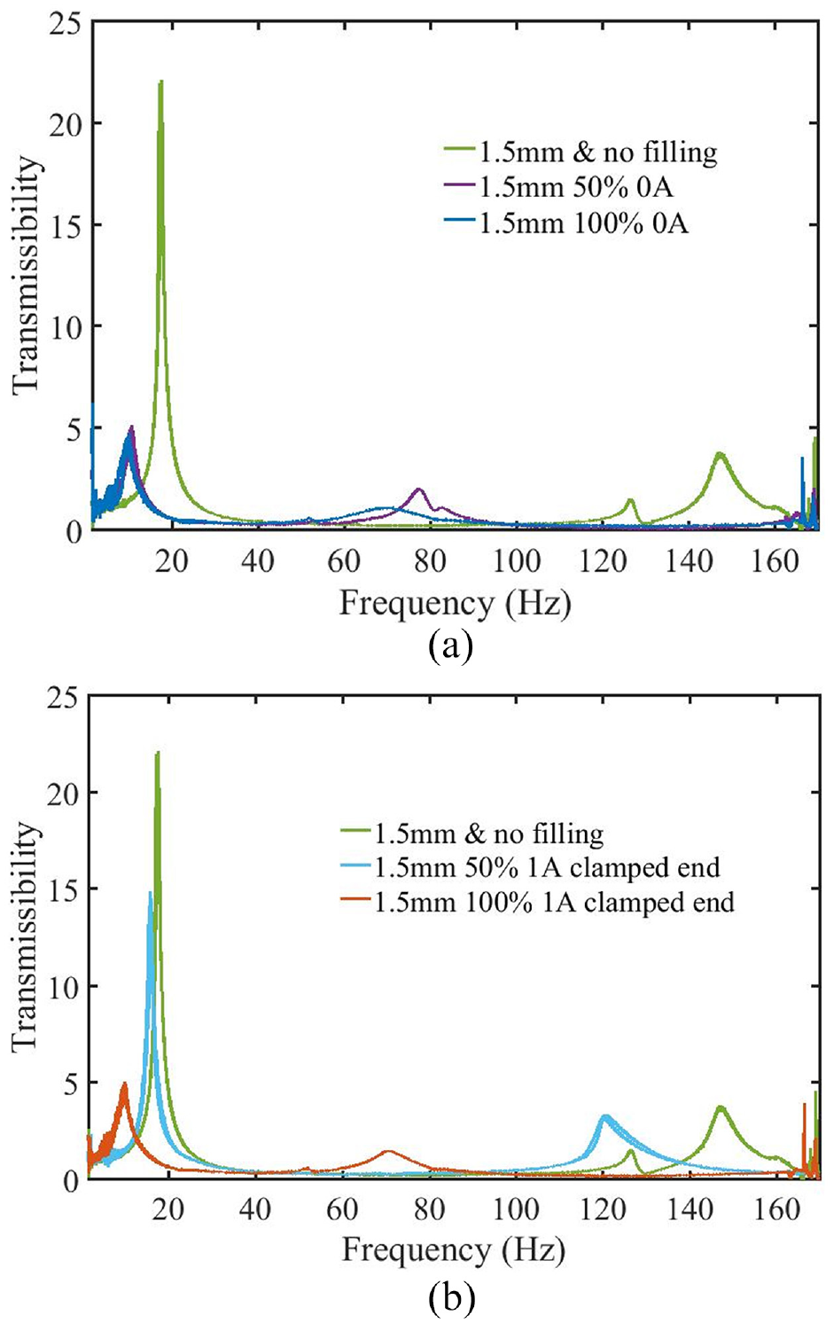
Acceleration transmissibility with different filling ratios: (a) 0 A and 1.5 mm and (b) 1 A and clamped end and 1.5 mm.
According to above experimental results, the filling ratio of MRF-PF is closely related to the damping property of the sandwich beam. With increasing the filling ratio, the first two natural frequencies and acceleration transmissibility decrease significantly. The damping property introduced by MRF-PF can effectively reduce the vibration and natural frequency. The vibration of the compound sandwich beam has been improved greatly by filling MRF-PF.
4.3.3. Characteristic of currents
The performance of the compound sandwich beam under different applied currents has been analyzed deeply in this section. When the current is applied into the clamped end, the frequency responses of the flexible beam with special configurations have been shown in Figure 14(a). It can be observed that the first natural frequency increases rapidly with the increase of the currents. This value ranges from 10.78 to 15.72 Hz with an increase of 45.8%. The second natural frequencies are 77.55, 119.2, and 121.5 Hz with various currents, respectively. With the further increase of the current, the frequency shift phenomenon becomes smaller in the first two natural frequencies. This effect may be caused by the magnetic saturation of MRF-PF. Meanwhile, this increase of the natural frequency is determined by the excitation current which is applied into the clamped end of the sandwich beam. Due to the distributed damping effect of MRF-PF, the compound sandwich beam becomes harder near the clamped end and the corresponding natural frequency increases with increasing the applied currents.
Vibration response of the sandwich beam with the thickness of 1.5 mm and excitation of the clamped end: (a) frequency response and (b) acceleration transmissibility.
What’s more, the acceleration transmissibility with this configuration has been shown in Figure 14(b). The transmissibility increases in the first two natural frequencies with the increase of the applied currents. Especially at the first natural frequency, these indexes are 5.16, 13.9, and 14.91 with different currents, respectively. It shows 188.9% increase which means that the vibration becomes more serious obviously under this condition. At the second natural frequency, the transmissibility increases slowly with an increase of 63.5%. Based on these experimental results, the acceleration transmissibility increases with the increase of the currents, especially at the first natural frequency. This effect is caused by the stiffness property near the clamped end of the compound sandwich beam. The effective stiffness increases dramatically and vibration becomes more serious with increasing the applied currents.
When the current is applied into the free end, the sandwich beam with the filling ratio of 100% has been analyzed. The frequency responses with different currents have been shown in Figure 15(a). The first natural frequency and the corresponding amplitude are almost the same at this condition. However, the second natural frequency decreases with increasing the applied currents. It ranges from 110 to 99.76 Hz with a decrease of 9.3%. Compared with the first mode, the vibration of the second mode has larger response and amplitude. The frequency shift phenomenon of the second mode can be easily observed than the first mode of the sandwich beam. It demonstrated that the variation of the natural frequency is little under different currents. The possible reason is that the stiffness of this sandwich beam is so large that the introduced damping effect can be ignored. When the current is applied into the free end, vibration deformation can be controlled and natural frequency decreases. Therefore, the first two natural frequencies decrease slowly with a small range.
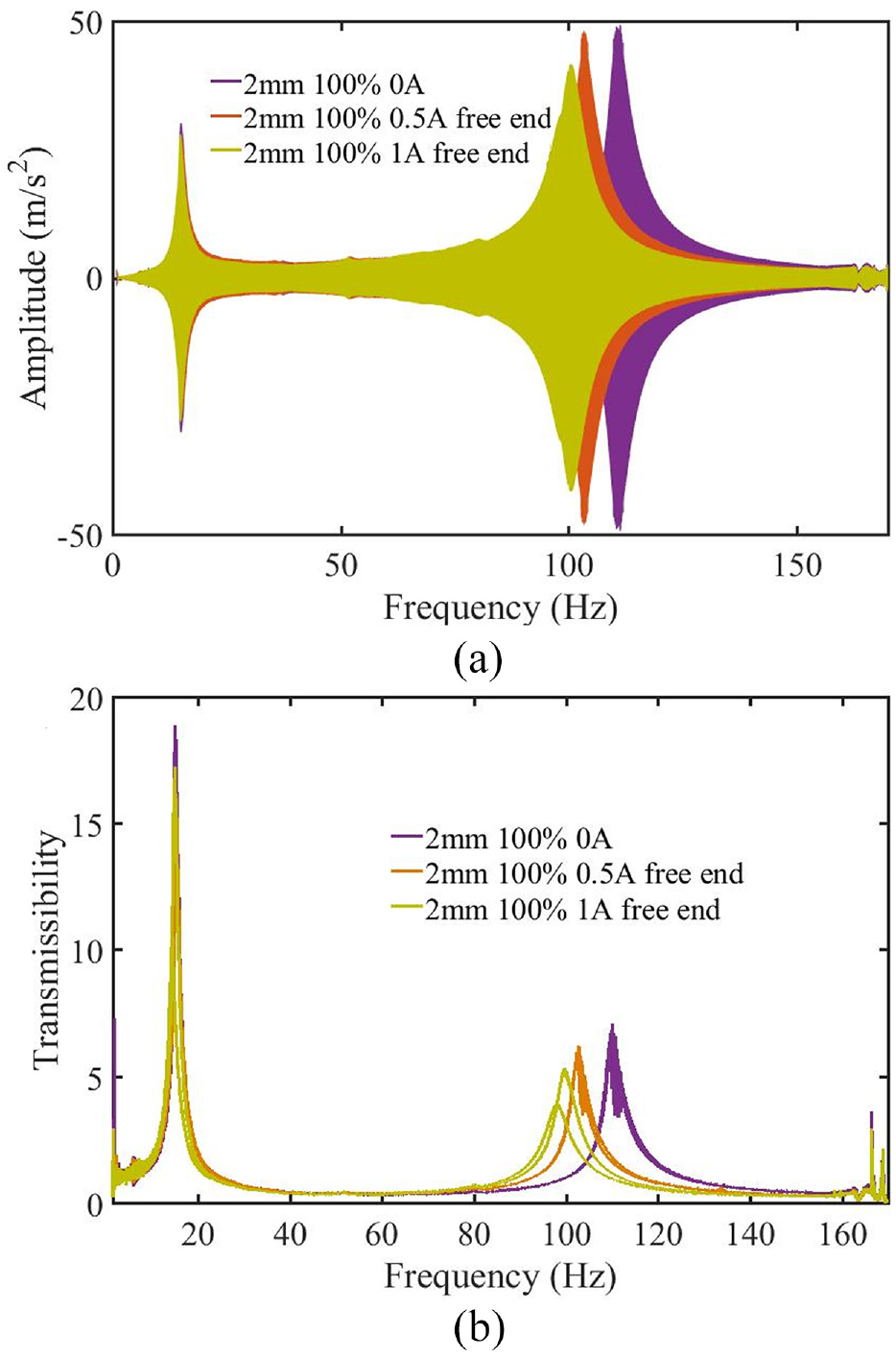
Vibration response of the sandwich beam with the thickness of 2 mm and excitation of the free end: (a) frequency response and (b) acceleration transmissibility.
The variation of the acceleration transmissibility has been shown in Figure 15(b). With the increase of the applied current, the transmissibility decreases gradually. It shows 8.67% and 24.9% decrease at the first two natural frequencies, respectively. This decrease is determined by the applied current and excitation position. When the external magnetic field is applied into the free end, the stiffness of the free end increases and the deformation of this part will decrease at the same time. The vibration of the compound sandwich beam is improved.
Based on the experiments and performance at the various applied current, the current is the primary influence factor of the acceleration transmissibility. Combined with the excitation position, these two factor have an effect on the frequency shift phenomenon.
4.3.4. Characteristic of excitation position
For the compound sandwich beams, excitation position is a significant factor of the output performance. The variation with different excitations positions has been quantitatively analyzed. The comparison of different sandwich beams has been shown in Figure 16.
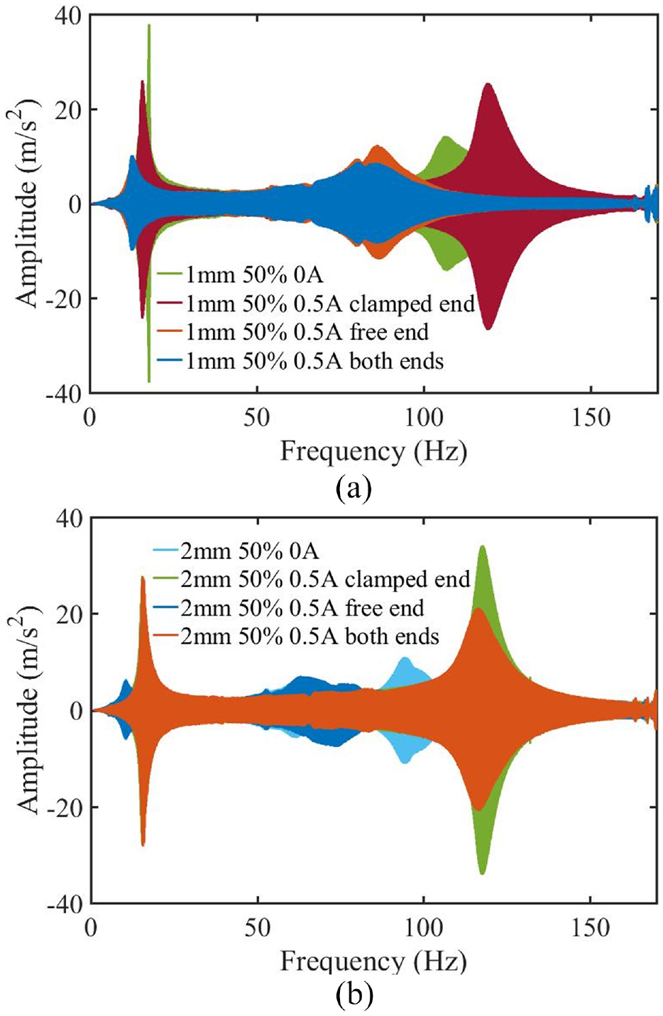
Frequency responses with different excitation positions: (a) 1 mm and 50% and 0.5 A and (b) 2 mm and 50% and 0.5 A.
With increasing the thickness of sandwich beam, the dynamic properties have the same variation at various excitation positions. When the current is applied into the clamped end, the first two natural frequencies and the corresponding amplitude increase gradually. For the sandwich beam of the thickness of 1 mm, the first natural frequency ranges from 15.09 to 15.87 Hz with an increase of 5.1%. The second natural frequencies are 106 and 118.9 Hz with different excitation positions, respectively. When the thickness increases to 2 mm, the frequency shift phenomenon is more obvious. This increase effect is closely related to the distributed property of MRF-PF. When the magnetic field is applied into the clamped end, the stiffness of the clamped end increases significantly. The deformations of sandwich beam mainly occur in the free end which is validated in Figure 6. The high stiffness in the clamped end will increase the vibration of the sandwich. Therefore, the natural frequency of the compound sandwich beam increases when the current is applied into the clamped end.
What’s more, when the excitation position is the free end, the natural frequency decreases rapidly. It shows 17.3% and 19.2% decrease of the thinner sandwich beam with the first two natural frequencies, respectively. With increasing the thickness, the natural frequency decreases at the same excitation position. It can be proved that the excitation at the free end can effectively reduce the natural frequency. The decrease is determined by the stiffness variation at the free end. When the magnetic field is applied into the free end, the local stiffness increases rapidly and the compound sandwich beam shows the harder state. The bending deformation at the free end of the sandwich beam will be suppressed effectively. The corresponding natural frequency of sandwich beam decreases simultaneously.
However, there is a difference of the dynamic property when the current is applied into the both ends. When the thickness of the sandwich beam is 1 mm, the first natural frequency of 12.67 Hz is slightly larger than the value at the free end under this conditions. The second natural frequency is almost the same with the value at the free end which is 85.9 Hz approximately. It means that the damping property of MRF-PF can effectively improve the vibration. When the thickness of the beam increases to 2 mm, the first two natural frequencies are 15.63 and 115.8 Hz with excitation of the both ends, respectively. These two frequencies are greatly larger than the frequencies at the free end. Comparing with different thicknesses, the first two natural frequencies increase significantly with increasing the thickness at this excitation. It may be caused by the stiffness property of the sandwich beam. With the increase of the thickness, the integral stiffness of the sandwich beam increases rapidly which plays a main role in the dynamic performance. The introduced damping effect of MRF-PF in the thicker sandwich beam can be ignored.
The acceleration transmissibility at these excitations is shown in Figure 17. The variations of the currents and excitation position can be validated. Under the excitation of the free end, the transmissibility decreases gradually and vibration has been improved. When the current is applied into the clamped end, this index increases with the frequency shift phenomenon. When the whole sandwich beam is excited, the dynamic property is dependent on the stiffness property which is determined by the thickness of the sandwich beam.
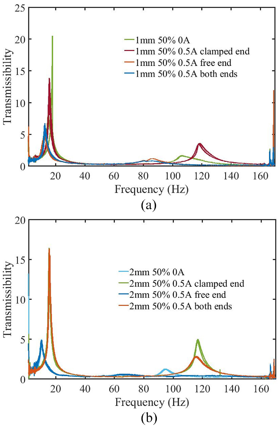
Acceleration transmissibility with different excitations: (a) 1 mm and 50% and 0.5 A and (b) 2 mm and 50% and 0.5 A.
Therefore, excitation position is significant to the dynamic properties of the sandwich beam with MRF-PF. The frequency shift phenomenon is related to the vibration deformation with the first two natural modes.
4.3.5. Validation and comparison
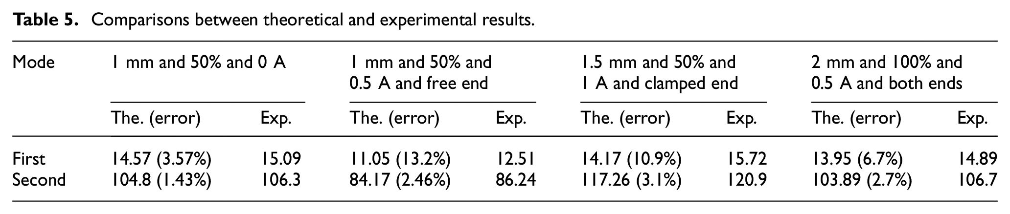
In order to validate the derived model, comparisons between theoretical and experimental results under different excitations have been listed in Table 5. The results indicate that the derived model can precisely describe the performance under different excitations. The maximum error is 13.2% under the specific excitation. The possible reasons are the distribution of magnetic field and binder between face plates. In this experiments, the magnetic field of the self-made magnetic field generator is not uniform outside the working region. What’s more, the aluminum plate is glued by the AB glue. The binder will increase the stiffness of the sandwich beam. Therefore, the measured frequency is larger than the theoretical result. Besides these, the errors are in a reasonable range under other excitations.
Comparisons between theoretical and experimental results.
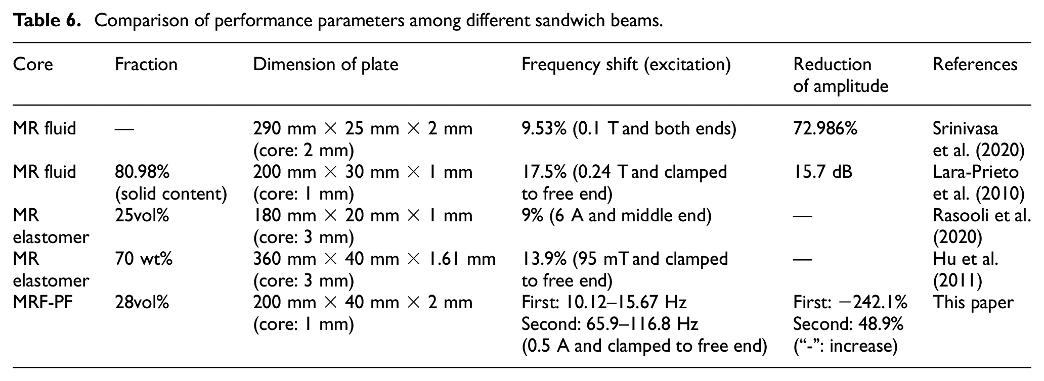
Meanwhile, the comprehensive comparison among different sandwich beams cored various MR materials is shown in Table 6. The performance parameters with different sandwich beams are listed to evaluate the mechanical properties qualitatively. According to experimental results, the frequency shifts under specific excitations are up to 54.8% and 77.2% with first and second natural frequencies, respectively. Comparing with other compound sandwich beams, the frequency range of the proposed sandwich beam cored MRF-PF is larger than other sandwich beams significantly. It means that the proposed sandwich beam incorporated MRF-PF has a better controllability with a larger dynamic range. What’s more, considering the geometric dimensions of the face plate, the proposed sandwich beam has a larger inertial moment than above listed structures. The measured results demonstrate that MRF-PF can effectively adjust the stiffness of sandwich beam as the core layer. This improvement may be determined by the internal porous network of MRF-PF. Particle chains are protected to reinforce the performance. However, the vibration isolating performance of this proposed sandwich beam is limited. In first order resonance, the excitation amplitude increases when the magnetic field is applied into the clamped end. This effect is determined by the excitation position. In second order resonance, the amplitude shows a decrease of 48.9% at the excitation position of the free end. Therefore, comparing with other sandwich beams incorporated MR materials, this proposed sandwich beam incorporated MRF-PF has a better dynamic property without any sealing mechanism.
Comparison of performance parameters among different sandwich beams.
5. Conclusion
This paper proposes a novel flexible sandwich beam incorporated MRF-PF with a well controllable capability. The main innovations are the performance evaluations of MRF-PF and the corresponding sandwich beam. As a novel MR material, fabrication and performance experiments of MRF-PF have been introduced and investigated. The pre-yield properties between complex shear modulus and magnetic fields in pre-yield region have been measured. It can be used into vehicle, tactile sensor, civil structure, and other engineering applications. Then, considering the excitation position, filling ratio, and MRF-PF, a theoretical model has been derived which can precisely describe the performance of the flexible sandwich beam incorporated MRF-PF. According to experimental results, the dynamic properties of this sandwich beam are determined by excitation position, filling ratio, and currents. When the magnetic field is applied into the clamped end, the natural frequency increases with increasing the applied current and filling ratio. On the contrary, the natural frequency decreases when the excitation works on the free end. Moreover, core layer of MRF-PF will increase the damping property of the sandwich beam to suppress the vibration. Comparing with different sandwich beams of various MR material, this proposed sandwich beam incorporated MRF-PF has a wider frequency range to enhance the controllability. The performance of the compound flexible sandwich beam is significantly improved by MRF-PF as core layer. Therefore, it can be widely utilized into many critical applications due to well performance.
Footnotes
Declaration of conflicting interests
The author(s) declared no potential conflicts of interest with respect to the research, authorship, and/or publication of this article.
Funding
The author(s) disclosed receipt of the following financial support for the research, authorship, and/or publication of this article: This research was financially supported by National Natural Science Foundation of China (No. 52075056), and additionally supported by Chongqing University Graduate Student Research Innovation Project (CYB21012).