
Abstract
Although failure mechanics and plasticity of composite materials is a relatively new and volatile field, it has been long realized in the composite materials community that a composite’s true integrity lies in the constituents’ interfacial health. Composite materials allow scientists and engineers to design structural architectures with directional stress, strain, and thermal fields in mind while simultaneously reducing the system’s overall weight. While there are advantages to using composite materials like carbon fiber reinforced polymers (CFRPs), designing and implementing long-term sustainable aerospace structures out of CFRPs is bottlenecked by the brittle catastrophic failure mechanism high strength carbon composites exhibit. As the demand for these materials in critical loading regimes increases, it is paramount that scientists and engineers understand how CFRPs will behave in real-time and in predictive models for load profiles. This research’s motivation comes from the US Army’s future vertical lift vehicle initiative to transition from interval-based maintenance to condition-based maintenance (CDB). This paper explores a real-time, non-contact, and non-destructive evaluation (NDE) method for composite materials by performing localized magnetic flux scans (32 mm2 field of view) of CFRP embedded with Terfenol-D (
Keywords
1. Introduction
Composite materials allow scientists and engineers to design structural architectures with considerations of directional, thermal, and material properties while simultaneously reducing the structure’s overall weight. While there are advantages to using composite materials like carbon fiber reinforced polymers (CFRPs), the disadvantages arise when designing and implementing long-term sustainable aerospace structures out of CFRPs. CFRP’s long-term implementation innovation is bottlenecked by the brittle catastrophic failure mechanism high strength carbon composites exhibit. Although failure mechanics and plasticity of composite materials is a relatively volatile field, it has been long realized in the composite materials community that a composite’s true integrity lies in the constituents’ interfacial health (Cole et al., 2017; Kaw, 2006; Myers et al., 2013: 991–1006).
A composite material is defined by a unit substrate that is composed of two or more constituents. In load-bearing CFRP components, the constituent of particular interest is the matrix material. The matrix material in CFRPs plays a vital role in the overall health, quality, and strength of the CFRP. Although in most composite materials the matrix material is the weakest constituent (with the fiber material being the strongest), it is responsible for maintaining fiber orientation, bonding lamina together, and transferring loads to the fiber material, along with many other environmental resistance duties (Cole et al., 2017; Haile et al., 2016; Kaw, 2006; Myers et al., 2013: 991–10067). In other words, it is the matrix material’s job to hold onto the fibers while the fibers carry the load. The criticality of this research is driven by the degradation of the matrix material in the form of damage precursors.
With respect to the US Army’s future vertical lift vehicles, damage precursors in CFRP structures are the dislocation density complex within the material that is associated with microscopic impurities that are not detectable using traditional sensing methodologies (Haile et al., 2016; Myers et al., 2013: 991–10067). These impurities can come in the form of voids, microcracks, crazes, etc. This research’s micro-scale interest has the potential to develop a powerful tool for micro-scale non-contact dislocation density detection, strain detection, localized stress detection, and high-resolution full-scale stress field detection. As seen in Figure 1 in the COMSOL Multiphysics model, it is possible to achieve micro-scale magnetic flux density sensitivity with MagCFRP. While Figure 1 is a FEM geometry cross-sectional view of the MagCFRP system, this current work is not simulation focused. This depict strictly serves as a visual representation of the system. Future works will include simulation setup and results.
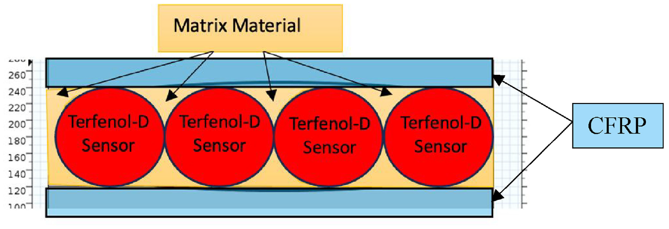
2D COMSOL Multiphysics FEA geometry model of Terfenol-D particles suspended in matrix material between fiber layers.
Due to CFRP’s low strain/toughness brittle fracture mechanics, it is paramount that future lightweight aerospace structures are smart and responsive as impending catastrophic failure can be imminent if not promptly detected. In other words, the US Army’s future aerospace vehicles need to be able to “feel” damage at a microscopic scale to warn, adapt, and survive in tactical situations. This paper explores a novel and sustainable methodology for Non-Destructive Evaluation (NDE) of CFRP interphase with implications to act as a data source for Structural Health Monitoring (SHM) machine learning schemes (Farrar and Worden, 2013; Nelon et al., 2022). Potential use cases for this work include but are not limited to NDE for condition-based maintenance, non-contact strain/stress sensing, and real-time composite SHM. The Army Research Laboratory (ARL) funded and motivated this research to revolutionize material use in their future vertical lift vehicles and weapons systems.
1.1. Review of NDE and methodologies
NDE of structural composite systems provides a strategy for damage detection across static and dynamic loading regimes without causing damage to the substrate itself in the process (Chang, 2013; Farrar and Worden, 2013). Monitoring and performing statistical analysis on damage-sensitive features (such as stress, strain, or, more specifically in this work, magnetic flux density) over an extended period can be used to determine the instantaneous state of a composite systems’ structural health and predict the systems’ future structural health (Farrar and Worden, 2013). NDE is a valuable solution in assessing CFRPs’ internal interphase health. However, there are no real-time, non-contact NDE techniques for localized interlaminar macro and micro-scale scanning.
The novelty of this research is that it explores a new real-time non-contact NDE method for aerospace composite structures and components. Most well-known NDE techniques include but are not limited to 3D Scanning Laser Vibrometry, Piezoelectric Wafer Active Sensors (PWAS), Acoustic Emissions (AE), Structural Thermography, Radiography, Well-Connected Nano Networks, Strain Gauges, Piezoelectric Sensors, Ultrasonic C-scans, X-ray CT (Computer Tomography) Scans, and Digital Image Correlation (DIC). While these techniques are useful in many applications, their scalability and practicality in robust applications can be limited to environmental and physical constraints. Using a non-contact NDE method such as Terfenol-D embedded CFRP (MagCFRP) has the potential to be used in a wide variety of applications while still possessing scalability and sustainability characteristics.
One widely used non-contact NDE technique is 3D Scanning Laser Vibrometry. 3D Scanning Laser Vibrometry uses a scientific instrument (Laser Doppler Vibrometer, LDV) to make non-contact vibration measurements of a surface. This technique is used for measuring stress wave propagation on the surface of a material rather than the extent and mode of internal damage (Ong and Chiu, 2014). The laser beam from the LDV scans the surface of interest for amplitude and frequency from the Doppler shift of the reflected laser beam frequency due to surface motion. Similar to Terfenol-D embedded CFRP surface scanning, LDV outputs are generally a continuous analog voltage. In LDV, the analog voltage is directly proportional to the target velocity component along the direction of the laser beam (Ong and Chiu, 2014).
In Ong and Chiu (2014), the condition of non-surface penetrating defects was assumed in their research and laser Vibrometry. Ong and Chiu explore the possibility of relating velocity field wave modes to structural defects. Their research uses metallic test structures, which do not possess the same strain/stress, failure, and defect characteristics as CFRP composites. Using this method in composite would be highly difficult due to the inter lamina configuration and interphase properties. In this work, they refer to idealized specimens concerning geometry rather than the type of material. Ong and Chiu showed that real-world geometry significantly alters the behavior of Lamp wave-based damage detection and, due to CFRP brittle and abrupt fracture mechanism, LDV may not even be a viable solution for surface defect monitoring of CFRP components. CFRP has an attenuating effect on high-frequency stress waves, allowing them only to be carried to a distance no longer than a few centimeters from the source location (Boshe, 2004).
The test specimens used in Ong and Chiu were made from 6 mm thick aluminum. A partial depth hole is machined on one side of the test plate. A 20 mm diameter partial depth hole simulated a non-surface penetrating defect. Two 10 mm piezoceramic (PZT) actuators initiated the stress waves. Before introducing the non-surface penetrating defect, the undamaged specimen was scanned to obtain a baseline. The damage was progressively increased following each scan. The scattering of the velocity was calculated by the differential of the velocity concerning time (i.e. Vscan = −|Vbase−Vdamage|) (Ong and Chiu, 2014). To accurately sense Lamp waves responses in a specimen with three-dimensional geometry, one must have a three-axis laser vibrometer experimental and production set-up. This highly integrated testing procedure raises the concern of sustainability due to the high amount of calibration required to use this system confidently.
In Ong and Chiu, a substantial amount of postprocessing must be performed before the raw data can be interpreted. Examples include MATLAB algorithm scripts to generate a time-varying visualization representation of the stress field and 2D FFT processing to understand the dispersion characteristics of the present stress waves. It is interesting to note that the scattered wavefield is more prominent outside of the partial depth damage and appears to be guided by the circumference of the partial depth defect, even though these measurements were taken on the flat side of the test specimen. This phenomenon can be a source of uncertainty in concentrated localized damage detection.
Another NDE/SHM technique is the piezoelectric wafer active sensor (PWAS). This technique is used to detect structural damage through wave propagation techniques. One of the main differences between the state-of-the-art PWAS approach and other conventional NDE techniques is that PWAS SHM uses permanently attached unobtrusive, minimally intrusive transducers. In contrast, the traditional NDE approach uses relatively large and expensive conventional ultrasonic transducers (Giurgiutiu, 2014: 639–703). Giurgiutiu believe their approach will lead to emerging new technology: embedded ultrasonic NDE. The authors propose this new method of embedded ultrasonic NDE to facilitate on-demand interaction of the structure to determine its current state of health and predict its remaining life. The premise of the PWAS NDE method is that the transducers can be used both as a receiver and a transmitter (pitch and catch). The pitch-and-catch technique is a test with a transmitter and receiver transducers, where the path of the ultrasonic beam is not a straight line but follows a complex path (Giurgiutiu, 2014: 639–703). The embedded pitch-catch method was discussed to detect through-thickness fatigue cracks in metallic structures and delamination in composite and other bonded structures.
The specimens under consideration in the reported studies ranged from simple geometries to full-scale aircraft-like panels (Giurgiutiu, 2014: 639–703). The presence of irregularities in the time-reversal reconstruction would indicate structural damage. It is stated that many NDE and Non-Destructive Testing (NDT) techniques exist for identifying local damage and detecting an incipient failure in critical structures. However, these techniques are mainly limited to the continuum level and shed very little insight on the micro, nano, and atomistic level. Ultrasonic inspection is well established and has been used in the engineering community for several decades (Krautkramer and Krautkramer, 1990). Ultrasonic NDE methods rely on elastic wave propagation and reflection within the material. This may not be practical for every environment. Due to CFRP’s anisotropy, non-homogeneity, and attenuating properties, using ultrasonic NDE may pose a significant challenge in extracting useful information in early damage detection.
Giurgiutiu tries to identify the wavefield disturbances due to local damage and flaws. Ultrasonic testing involves one or more of the following measurements: time of flight (TOF) (wave transit or delay), oath length, frequency, and phase angle (Giurgiutiu, 2014: 639–703). Good contact between the transducer and the structures is obtained using special coupling gels, which adds another layer of complexity to the system. Depending on the transducer type and its bond to the structural surface, the waves created in the structures may be P- waves, S-waves, or a combination of the two (Giurgiutiu, 2014: 639–703). Combining P-waves and S-waves can make defining defects or damages challenging. Ultrasonic inspection of thin-walled structures (e.g. aircraft shells, storage tanks, large pipes, etc.) is time-consuming and requires meticulous through-thickness C-scans over large areas.
Another novel and relatively new approach to SHM of composite components is Electrical Impedance Tomography (EIT). The premise of this research method is to integrate electrically conductive scanning into nanocomposites for self-sensing and health monitoring. EIT SHM correlates local changes in conductivity to damage. This method uses conductivity changes and imaging conductivity evolution in a carbon nanofiber-filled epoxy matrix composite, theoretically allowing the entire matrix to become self-sensing (Tallman et al., 2014).
With this method, a significant thermal effect must be considered. Tallman states that their tests indicate that thermal expansion is responsible for conductivity evolution in a carbon nano-fillers (CNF)/epoxy composite. As advanced and evolutionary as EIT is, researchers are still taking a proof-of-concept approach in recent work (Tallman et al., 2014). Embedding carbon nanofiber into the matrix material of the composite can have a significant positive impact on the interlaminar and overall strength of the composite. It is reported by Zhu et al. (2012) that embedding CNFs into matrix composites can yield up to a 57% increase in mode I and mode II fracture toughness (Zhu et al., 2012: 1316–1331).
Along with the boost in mechanical properties, embedding these CNFs is the sole mechanism that allows for damage detection in composite by monitoring the changes in impedance. Theoretically, this method is sublime. However, achieving this balance between mechanical and electrical properties in practice can be highly challenging. Tallman write that the electrical conductivity of polymers filled with conductive nanofillers depends on the formation of well-connected networks of the filler material. Once these well-connected nanofillers are severed by damage, there will be a change in the material conductivity (Tallman et al., 2014). This would pose a substantial challenge in full-scale aeronautical component manufacturing due to the high sensitivity to nano-manufacturing.
The EIT method also has limitations in that the composite fibers must be conducting, and the matrix is insulating. EIT uses the conductivity distribution from a specified domain boundary to create a visual representation of field impedance (Holder, 2005; Tallman et al., 2014). Tallman states that EIT has tremendous potential for SHM because it requires minimally invasive measurements and can be employed in nearly real-time and for a low cost (Tallman et al., 2014). No further comments were made about what exactly is “nearly real-time” or the magnitude of EIT’s “low cost” compared to other traditional SHM methods. Although it is stated by Tallman that this method is “minimally intrusive” and has a “low implementation cost,” it is worth noting that to scan a 54 mm × 52 mm × 5 mm specimen, one needs 16 electrode pairs to receive a current injection for tomography (Tallman et al., 2014). CFRPs embedded with Terfenol-D require no physical contact to observe magnetic flux response.
One of the main modes of failure that EIT is interested in is delamination. The approach is to provide full-field matrix material sensing to detect the progression of delamination in small composite panels. Studying current flux through a CFRP system is an intricate process that requires a high level of knowledge in tensor calculus, electrical engineering, and composite mechanics. Some issues arise with reconstructions for damaged and undamaged specimens due to electrode placement mismatches (Tallman et al., 2014).
The tested CNF specimen in Tallman was not integrated into a functional composite laminate. It was just an epoxide/acetone/Triton X-100 mixture cured in a silicone mold (Tallman et al., 2014). In the testing procedure, the damage was simulated by drilling a 6.5 mm diameter hole through the material (Tallman et al., 2014). With damage precursors in mind, this mode of damage to a structural composite component is severe on the continuum level and could lead to catastrophic failure in a structural part. This damage mode would also be evident with a much simpler and traditional visual inspection.
Due to the EIT reconstruction errors, even the undamaged baseline results can be misleading. Multiple low conductive regions produce similar responses and the damaged specimen. With that in mind, the approach of Tallman is to study the gradient between the tomography scans rather than the raw data. Although this method is unique and novel, its high complexity, unknown scalability to full-scale composite laminate, and damage sensitivity hurt it in being considered a realistic solution for full-scale SHM in aeronautical vehicles.
1.2. Solutions for damage detection
Due to this research’s end-user and potential applications, the Army Aeronautical Design Standards Handbook (ADS-79E-HDBK) was heavily considered in the overall development and use-case standards for MagCFRP used in NDE, SHM, and Condition Based Maintenance (CBM). Knowing the instantaneous interfacial health of CFRP could revolutionize how composite materials are used, studied, and maintained. ADS-79E-HDBK defines Condition Based Maintenance as the application and integration of appropriate processes, technologies, and knowledge-based capabilities to improve the target availability, reliability, and operation and support cost of DoD systems and components across their lifecycle. More concisely, CBM is maintenance based on the actual condition of the system/component. The CBM approach is the Army’s effective and sustainable target standard that will eventually omit other maintenance methodologies like interval-based maintenance, where parts are replaced at time intervals, regardless of the component’s structural integrity. The development of advanced composite-specific material characterization techniques like MagCFRP is essential if the US Army’s CBM protocols are going to be applied to future high-stress aeronautical CFRP components.
The current development iteration of MagCFRP is classified as an embedded diagnostics/prognostics methodology by the ADS-79E-HDBK section 4.2 standards. This methodology is defined for systems that can detect condition indicator faults (e.g. changes in magnetic flux signatures over time). For these embedded diagnostics/prognostics methodology capabilities’ to be extended to CBM functionality, the characteristics of sensor technology, data acquisition, sensor selection, and algorithm efficacy must be considered. Once the MagCFRP embedded diagnostics/prognostics methodology is well-define, the CBM functionality characteristics will be considered in future works.
1.3. Working principles
The mechanical behavior of fiber-dominant pre-perg CFRP components post-fabrication is brittle. While CFRP components have inertial advantages over traditional metallic materials, CFRP exhibits minimal energy absorption before failure compared to ductile materials (e.g. aluminum alloys). While this brittle and catastrophic mechanical failure behavior may be true on a continuum level, the damage progression of the fiber-matrix interphase on the micro-scale level is continuous and compliant. The premise of MagCFRP for NDE with SHM implication revolves around damage sensitivity elongation via small-scale magnetostriction theory. Damage sensitivity elongation for MagCFRP is a method developed to extract critical fiber-matrix interfacial health information by embedding micro magnetostrictive particulate into the matrix material.
Due to the vacuum-assisted autoclave fabrication process’s inherent nature, an interlaminar compressive residual stress exists between plies. Since the Terfenol-D particles are embedded between CFRP plies, the particles are also subject to this compressive residual stress. The Villari effect and other fundamental principles of magnetostriction suggest that this compressive fabrication stress field around the embedded Terfenol-D particles will directly affect the local magnetic signature. This post-fabrication pristine magnetic signature for a MagCFRP system is spatially unique. Using this spatially unique magnetic signature, a strong baseline can be established. The first law of thermodynamics states that when a system goes from an equilibrium to a non-equilibrium state, there is a net decrease in energy. In the MagCFRP working system, the magnetization equilibrium state is defined by the residual magnetic flux density field in a pristine component post-fabrication when no load or stress has been applied. This residual flux is a product of the residual stress after fabrication. Crack formations will begin when excess loads, stresses, and strains are applied to the CFRP component. These crack formations in the matrix material are the mechanisms that lead to the transition to a non-equilibrium state in both magnetization and stress. The net decrease in energy of the MagCFRP system transitioning from an equilibrium to a non-equilibrium state is a product of the energy released from bonds breaking during the crack growth process.
Fracture generally occurs when the crack tip stresses overcome cohesive forces that keep neighboring atoms or molecules at equilibrium spacing. In a MagCFRP system, the cohesive force of predominant interest is the cohesive force and stress of the Terfenol-D and the 8552 epoxy resin molecules as depicted in Figure 2.
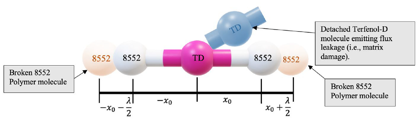
Molecular diagram of Terfenol-D bonded with 8552 molecules at equilibrium and cohesive spacing.
In Figure 2, x0 is the equilibrium spacing between the Terfenol-D and 8552 molecules and λ is the bond energy wavelength between the Terfenol-D and 8552 molecules. Once the cohesive stress is overcome by external mechanical stress, there will be a release in bond energy. Bond energy is released when a fracture occurs, and new surfaces are created. Because of Terfenol-D’s magneto-mechanical coupling and the Villari effect, this release in bond energy will relate to a localized change in the magnetic flux density during scanning. Using a magnetometer, the change in residual magnetic flux density data directly relates to interlamina energy released from matrix cracking. The new fracture surfaces created around and along the Terfenol-D-epoxy interphase will change the stress field surrounding the Terfenol-D particles, changing the magnetostrictive response. This process of detecting changes in magnetic response can be best described as an extension of Indirect Magnetic Particle Inspection (MPI) methods, where an external source magnetizes the paramagnetic CFRP component, and the subsurface magnetostrictive response is tracked using magnetometry.
Figure 3 is a schematic of the MagCFRP based on the composite cylinder assemblage (CCA) elasticity model where the fiber-composite constituent arrangement is in an cylindrical coordinate system. While there are some apparent inconsistencies between Figure 3 and Figure 4, there are not identical representations of the MagCFRP system. Figure 4 is an X-ray CT cross-sectional scan. This figure was only intended to show the deposition density field of the Terfenol-D particles within the CFRP rather than the spatial orientation.
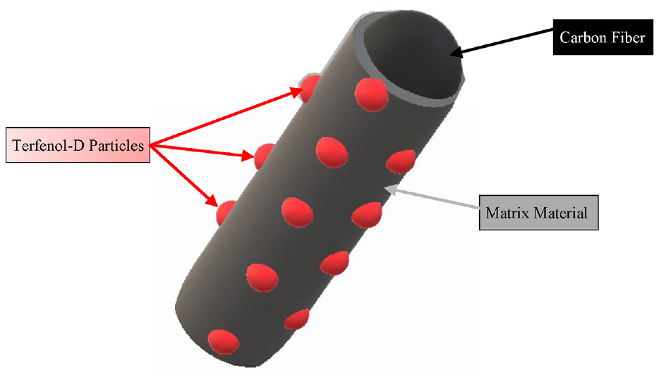
Floating diagram of MagCFRP constituent system. The Terfenol-D particles (depicted as red spheres) are embedded in the matrix material (gray matter) that is surrounding the carbon fiber (black cylinder).
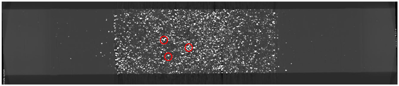
Interlaminar cross-sectional X-ray CT scan of Terfenol-D embedded in CFRP (examples of conglomerate formations are circled in red).
2. Materials and methods
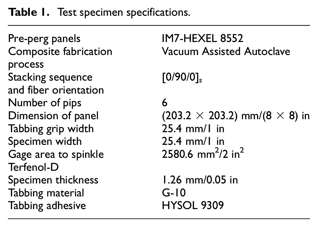
The 10 baseline CFRP samples were not embedded with Terfenol-D particles. The baseline CFRP samples were manufactured using the exact specifications as the Terfenol-D CFRP sample, as seen in Table 1. The baseline sample testing allowed for strength, toughness, and non-ferroic material interaction verification.
Test specimen specifications.
2.1. Terfenol-D embedded CFRP fabrication
Since the magnetostrictive material is embedded within the matrix material, the Terfenol-D weight percent (wt.%) was calculated concerning the matrix material rather than the entire composite. Before fabricating the carbon fiber panel using the vacuum-assisted autoclave process, 15 wt.% of the Terfenol-D powder was embedded evenly between each ply using a sprinkling deposition technique. This sprinkling deposition technique is not ideal for future production applications, as the distribution of Terfenol-D particles is highly non-homogeneous. This non-homogeneous distribution of Terfenol-D particles can be depicted in Figure 4. As seen in Figure 4 circled in red, the sprinkling deposition technique form conglomerates of Terfenol-D. Cole et al. (2017) and Zhu et al. (2012: 1316–1331) reported that adding constituents to the fiber/matrix interphase can increase shear strength. However, this increase in strength is for ideally deposited substrates rather than the conglomerate formation present in this work. More technical discussion of mechanical properties resulting from this deposition technique will come in section 3 of this research paper.
This embedding process was done on a magnetic chuck to pre-align the dipole moments of the Terfenol-D deposited within the MagCFRP. The magnetic domain pre-alignment direction is in the out-of-plane normal direction to the composite sample. The inspiration for pre-aligning the magnetic dipole moments using a magnetic chuck came from magnetostrictive researchers such as Hamann and Dahlberg (2017: 1–3) and Shanmugham et al. (2004: 267–274), who believe pre-aligning the dipole moment of magnetostrictive material will yield a more significant response to induced magnetization (Lacheisserie, 1993: 5–60; Seifu, 2018). The pre-aligning magnetic dipole moments of the embedded Terfenol-D material can be visualized in the pre and post SEM images taken by Shanmugham of Terfenol-D particles in an epoxy matrix, as shown in Figure 5. As depicted in Figure 5(b), the interfacial crack density of the non-magnetically aligned Terfenol-D particles is twice as much and more fragmented when compared to the pre-aligned Terfenol-D particles (Figure 5(c)). Shanmugham and Bailey suggest that this high crack density interfacial failure seen in Figure 5(b) is likely due to the low tensile strength of the ground particles. Increasing the tensile strength of the particle should improve interfacial resilience. All Terfenol-D embedded CFRP test specimens were pre-aligned using a saturation flux magnetic chuck to avoid post-testing inflated crack densities along the matrix-particle interphase due to the non-magnetically pre-alignment.
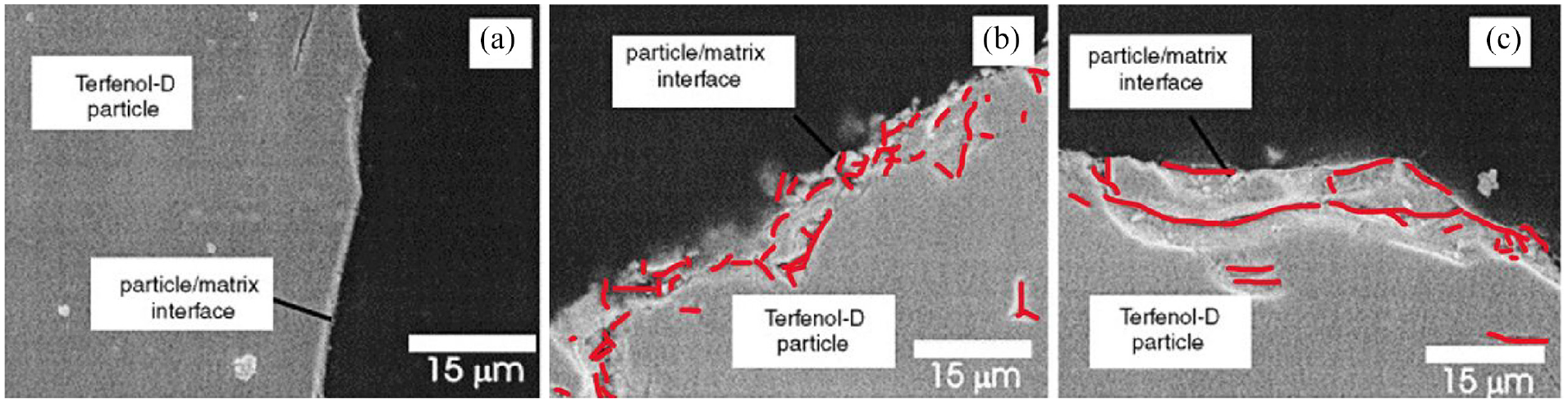
(a) Untested epoxy-resin/Terfenol-D particle interphase, (b) non-magnetically aligned epoxy-resin/Terfenol-D particle interphase (crack orientation label in red), and (c) magnetically aligned epoxy-resin/Terfenol-D particle interphase (crack orientation label in red). (Shanmugham et al., 2004: 267–274) (Copyright Approved, License Number-5294610994449).
The Terfenol-D deposition process took place inside an Argon glove box due to Terfenol-D’s pyrophoric nature. After the Terfenol-D deposition process, the embedded CFRP panel was sealed and transferred to an autoclave machine for processing and curing. Equipped to each sample were four G-10 tabs bonded to the specimen using HYSOL 9309, a high-strength adhesive. These tabs allowed the specimens to be gripped by the mechanical testing system without creating stress concentration and preventing delamination at the ends of the carbon fiber specimen.
2.2. Mechanical testing equipment
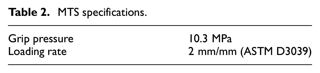
A mechanical testing system or load-frame is a high stiffness hydraulically controlled device used to apply force to the material so that the physical response of the material can be observed (e.g. longitudinal strain, lateral strain, flexural strain, compress strains, etc.). This research specifically used the MTS 370.25 load frame to perform the tensile test on the CFRP specimens. This load-frame was programed using the MTS software to apply quasi-static and load steps tensile tests on the baseline and MagCFRP specimen. While the ASTM D3039 quasi-static tensile testing protocol used is standard, the load-step testing protocol was manually driven by acoustic emission response, which will be discussed in greater detail in Section 3. Readers can find the necessary MTS testing specifications in Table 2. All the baseline and most of the MagCFRP test samples were taken to failure for material strength and toughness analysis.
MTS specifications.
After completing the mechanical testing, the load-frame induced interfacial damage on two Terfenol-D embedded samples to perform magnetoelasticity analysis. Although two samples were tested, only one is reported in the paper because of inconclusive X-ray CT scanning.
Due to limited space and overall repeatability of the testing methodology, the test samples’ axial displacement and strain data were collected using 2D DIC over a traditional extensometer or surface adhered resistivity strain gauge. The testing DIC specifications can be found in Table 3.
DIC specifications.
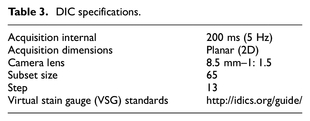
The 2D DIC assumptions that this research makes are that the camera was mounted and remained perpendicular to the specimen’s surface throughout testing, and the camera’s optical axis remained on the specimen’s geometric center surface, where the out-of-plane movement is considered negligible. The test samples were speckled using the Sharpie technique (Speckle Pattern Fundamentals, n.d, www.correlatedsolutions.com). Before speckling using a black Sharpie, the samples were first coated with a TOUGH GUY 4WGD2 multi-purpose flat white matte white paint finish to provide sufficient contrast for the DIC. Figure 6 illustrates a DIC post-process example of the global
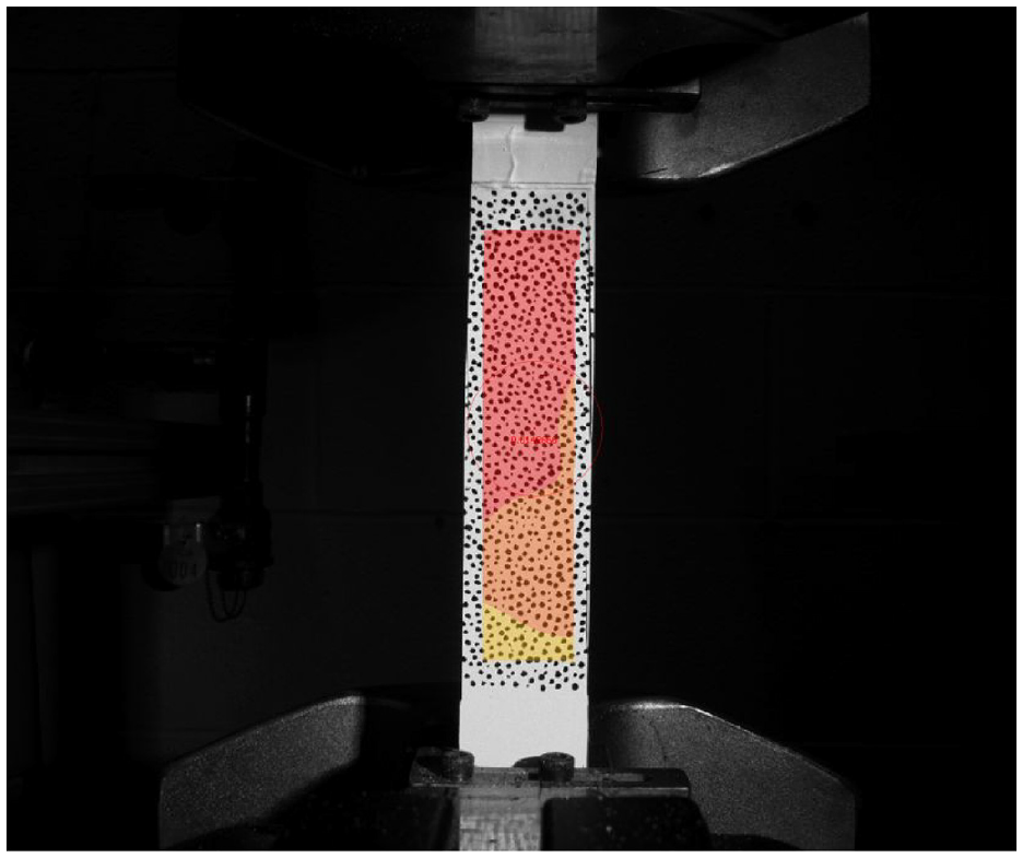
DIC post-processing example.
2.3. Auxiliary testing equipment
Magnetic measurement equipment was used to detect the magnetic flux change across the Terfenol-D embedded CFRP test samples. The magnetometer used in this research was the Pacific Scientific Model 6010. This magnetometer uses an attached axial probe with a Hall Generator connected to the end, as seen in Figure 7. The Hall Generator measures magnetization changes by calculating changes in current and voltage between four leads attached at the midpoint of each edge of a semiconductor material. The Hall voltage also depends on how the flux lines pass through the material. The Hall Generator is positioned normal to the test specimen and concentric to the neodymium magnetic discussed later in this section. Although the actual probe is parallel to the magnetic flux, the Hall Generator’s orientation is still perpendicular to the flux. Using this magnetometer allowed the magnetic flux response through the specimen to be measured and recorded in real-time without contact. The magnetometer has an active area from 0.2 to 19 mm in diameter. The target uniform driving magnetic flux value was 155 mT ± 5 mT.
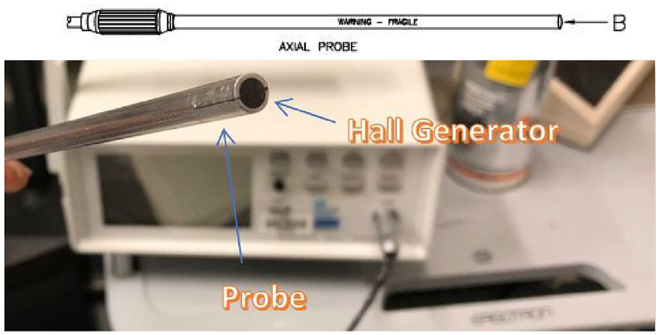
Parallel (axial) field probe for Hall generator.
In the original test plan specifications, the uniform driving magnetic flux density was to be generated by Helmholtz Coils, which are air wound coils of large diameter connected to a power supply aligned on a common axis for the measurement and study of magnetic fields. Depicted in Figure 8 is the original testing fixture of the Helmholtz Coils connected in a series circuit. When the Helmholtz Coils’ axial distance is set and connected in series, a uniform magnetic flux is generated along the coils’ neutral axis. However, an in-plane field gradient of −0.0067 mT/cm from the mid-point outward in the radial direction was observed, which is not desirable for testing. The governing equation for the magnitude of magnetic flux produced at the center of the coil, derived from the Biot-Savart law:
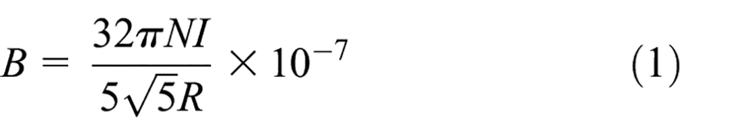
where
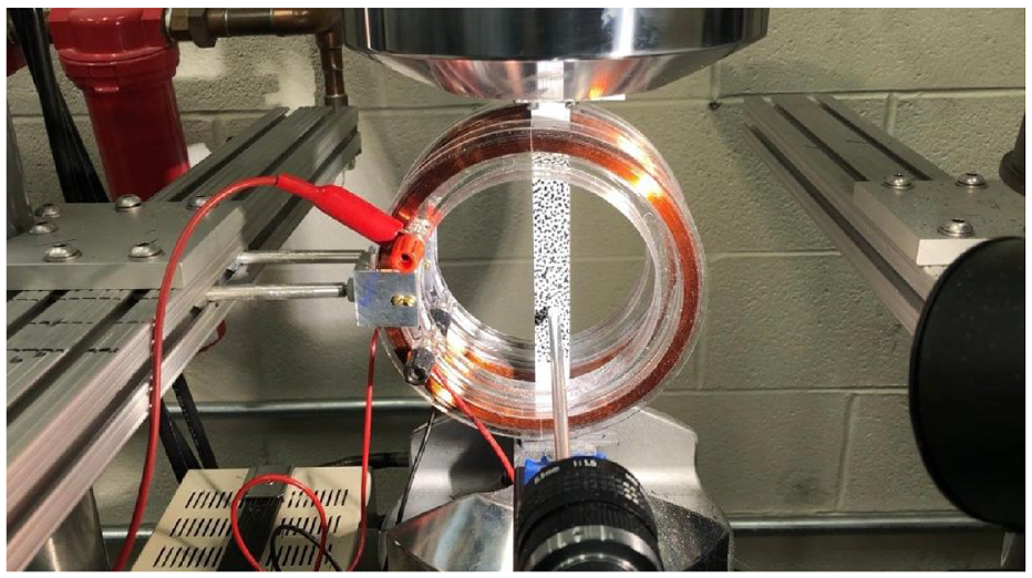
Helmholtz Coils testing setup.
The coils’ performance depends on their operating temperature that is, higher coil temperature yields higher resistivity. Integrating this first-order uncertainty (and propagation of uncertainty, as equation (1) is not valid as B is also a function of temperature and time) source into the system was one of the primary factors in deciding not to use the Helmholtz Coils. Cooling systems for similar electromagnetics are available. However, the cost of these cooling systems is premium. Due to the relatively large radius of the coils, the produced magnetic flux was not significant enough to interact with the Terfenol-D embedded CFRP since the saturation magnetization of Terfenol-D is around 1 T. The large radius of the Helmholtz Coils also caused them to be a source of error, as the surrounding testing equipment, mainly the MTS grips, interacted with the generated field, which induced a change in magnetic flux due to the actuator distance from the coils. As the actuator moves during testing, this produces a source of error.
Dr. Derje Seifu of Morgan State University has done torque magnetometry work with 15 wt.% embedded Terfenol-D in CFRPs. His work shows that in a relatively small magnetic field (around 0.5–1 kOe), the observed torque is negligible (±100 Dyne-cm for
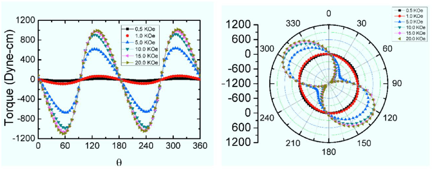
Torque magnetometry of 15 wt.% MagCFRP sample (Seifu, 2018).
The strongest field generated by the Helmholtz Coils was around 0.05 kOe. Dr. Derje Seifu’s magnetometry work validates this suspected weak interaction. Even when a 15 wt.% Terfenol-D sample was suspended between the Helmholtz Coils, there was no appreciable change in
Permanent/neodymium magnet specification.
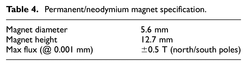
The neodymium magnet dimensions were also a significant factor in using permanent magnets over other electromagnets. The magnetic poles of the neodymium magnet have the same diameter as the Hall generator probe. The uniform diameters between the source (neodymium cylindrical magnet) and receiver (Hall Generator) allowed for a uniform and localized magnetic flux across the test specimen. The target distance between the neodymium magnet and the Hall generator probe placed from the test specimen’s surface was 1.35 mm, respectively. Variation of this target distance on either side will affect the driving flux recorded by the magnetometer. Once the test setup is set, the distance between the magnet and the Hall generator probe remains unchanged. The permanent magnet produced a large enough magnetic flux to physically interact with the Terfenol-D particles embedded in the test specimen. The magnetic flux generated by the magnet was significant enough to cause a net body force that moved and stuck to the MagCFRP specimens in the pendulum test, as seen in Figure 10 below.
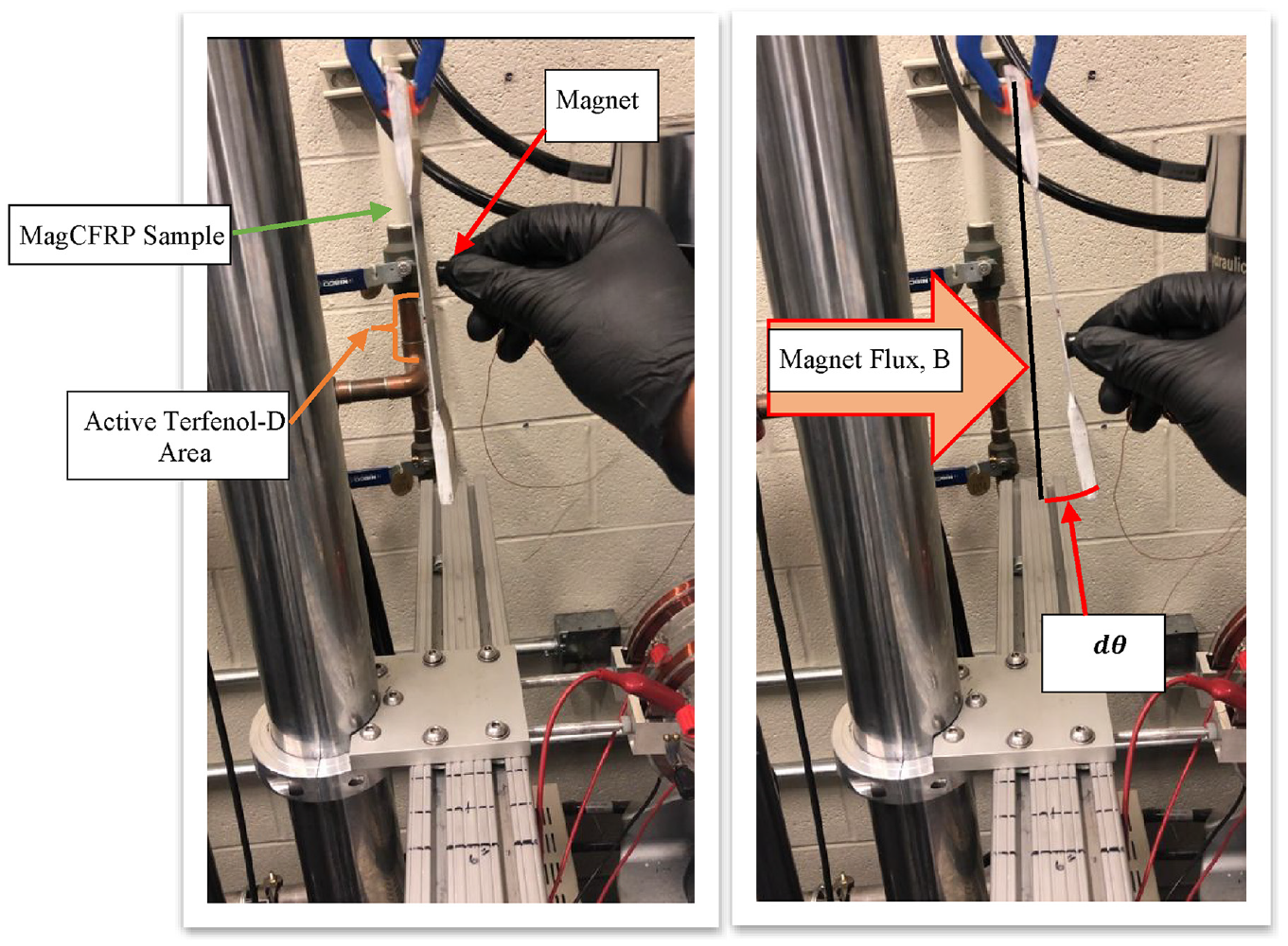
Before (left image) and after (right image) magnetic flux was applied to hanging MagCFRP sample.
AE is a well-known, well-respected method for analyzing damage propagation in composite materials. It uses highly sensitive piezoelectric transducers that passively detect acoustic (elastic stress or pressure) waves by dynamic surface motion on the sub-nanometer scale and convert it into an electric signal (Chang, 2013). AE sensors were attached 25.4 mm away from the localized scanning region of the Terfenol-D specimens during quasi-static testing. This placement of the AE was done to correlate the internal damage with the magnetization response. This final test setup is illustrated in Figure 11.
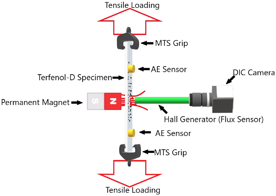
Magnetostriction testing diagram using permanent magnet.
3. Results and discussion
The 15 wt.% MagCFRP magnetostriction analysis was performed on the same sample. Figure 12 illustrates normalized stress versus localized magnetic flux density versus strain graphs of each non-ferromagnetic baseline specimen. The stress axis was normalized with an average UTS of 1.6 GPa to make a direct correlation between failure stress and magnetic flux density values. This allowed for relationships to be studied regardless of the composite stacking sequence. The vivacious diagonal lines illustrate the stress versus strain curves of the baseline CFRP samples. These linear stress/strain curves are associated with the left y-axis (Normalized Stress), and the horizontally oriented lines are associated with the right y-axis (Localized Magnetic Flux Density). The magnetic flux density data in Figure 12 (the horizontally oriented colored lines matching their respective loading profile) illustrates a uniform driving flux produced by the permanent magnet. As expected, there was no observed magnetoelastic response from the baseline samples that were not embedded with Terfenol-D, as the CFRP is a non-ferromagnetic material. This non-ferromagnetic interaction can be visualized in the strictly horizontal magnetic flux lines in Figure 12. As the load is increased on each specimen, there is no change in magnetic flux density.
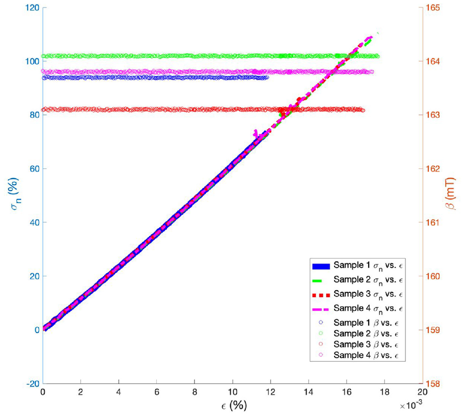
Strain versus normalized stress versus localized magnetic flux density of baseline samples.
The difference in the driving magnetic flux density values can be attributed to the difference in distance between the magnet and the Hall generator probe. The first-order magnetometer uncertainty was ±0.0178 mT. This uncertainty is not a measure of variance between the unique driving magnetic flux density curves but a measure of variance in the magnetometer. All baseline and Terfenol-D embedded CFRP samples were taken to failure.
3.1. MagCFRP 15 weight mechanical results
When comparing two unique materials, it is essential to compare the difference in the strength of the materials. Specific to the MagCFRP system, it is necessary to understand how changes in deposition technique change the strength of the material when compared to baseline material strength data. Figure 13 illustrates the linear regression of the stress versus strain data for the baseline and 15 wt.% Terfenol-D embedded MagCFRP samples. Like the baseline samples, the 15 wt.% Terfenol-D embedded MagCFRP also had an average UTS of 1.6 GPa. Although the average UTS of the baseline and 15 wt.% samples were the same, mechanical analysis of the stress versus strain data showed a 4% reduction in strength and a 6% reduction in toughness between the baseline and 15 wt.% samples. The baseline samples also have a higher modulus of elasticity (approx. 102 GPa) when compared to the MagCFRP samples (approx. 100 GPa), as seen in Figure 13.
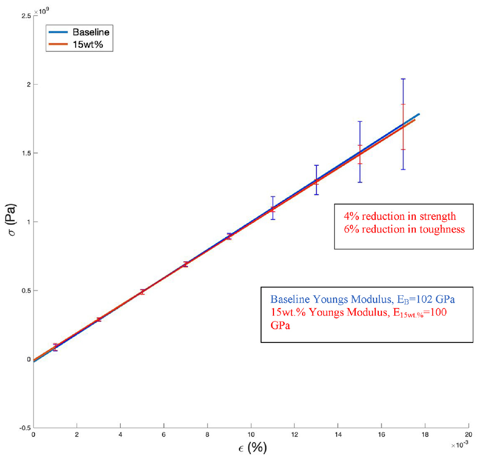
Strain versus stress plot of baseline and 15 wt.% MagCFRP.
Terfenol-D’s magneto-mechanical coupling properties have the potential to increase interphase shear strength and shear modulus within the fiber-matrix-particle interphase bonding (Cole et al., 2017; Haile et al., 2016; Zhu et al., 2012: 1316–1331). With improvements in deposition and fabrication, it is hypothesized that the Terfenol-D substrate will increase the shear modulus and overall strength of the MagCFRP material.
3.2. MagCFRP magneto-elastic response results
A load-controlled test was performed on the MagCFRP to study the localized magnetic response. The load increments were 5% UTS up until 40% UTS was achieved to detect early damage precursor and the onset of interphase cracking. The step intervals were manually controlled concerning the AE activity. When the AE “events” ceased, the load profile was increased by 5% UTS. Once 40% UTS was achieved, the load was stepped back down in 5% increments until material stress of 0% UTS was achieved. All the AE, load, and magnetization data were recorded via a data acquisition computer (DAC) at a sampling rate of 1000 Hz for uniform test step acquisition (Figures 14 and 15).
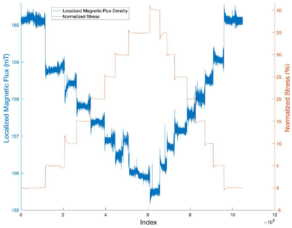
MagCFRP localized flux density versus normalized stress (0%–40% UTS) versus index.
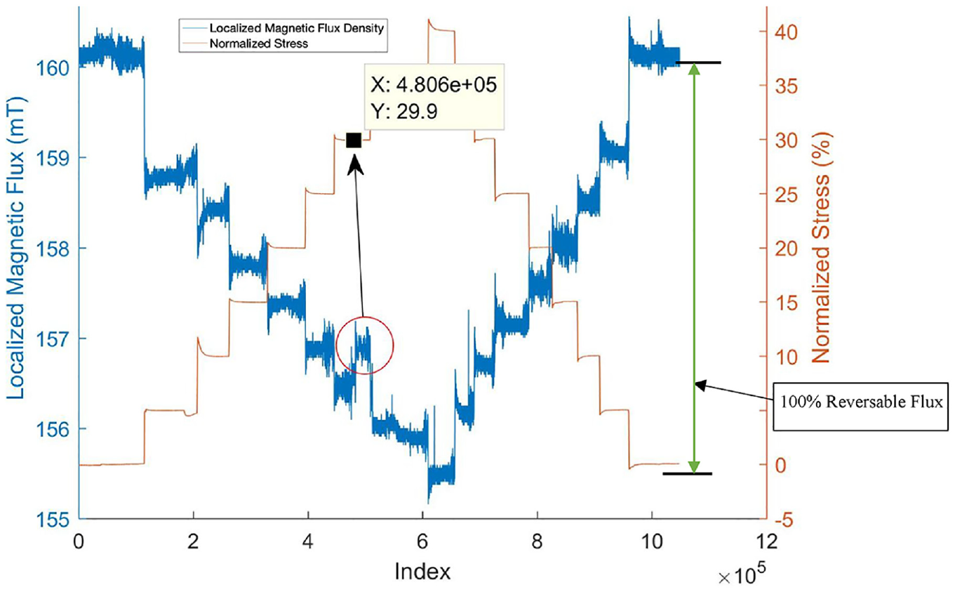
MagCFRP localized flux density versus normalized stress (0%–40% UTS) versus index (damage precursor and reversable flux marked).
Figures 16 and 17 illustrate the relationship between the localized (32 mm2 FOV)) magnetic flux density responses (left y-axis) and normalized stress (right y-axis normalized by averaged failure stress) concerning time (index). The inertia effects were neglected since the testing procedures are not dynamic. Thus, this system’s independent time component was converted to an index component, observing that all parametric data were sampled at the same frequency and time step.
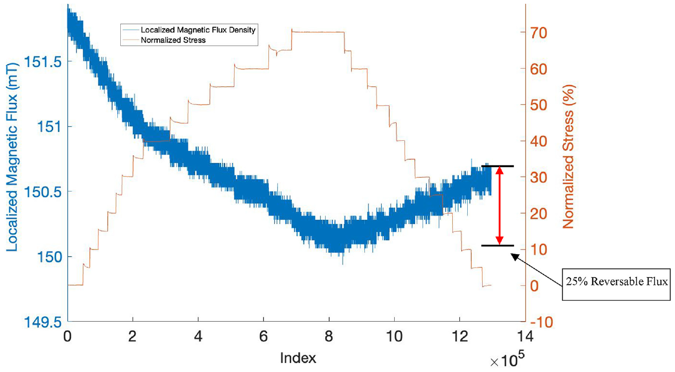
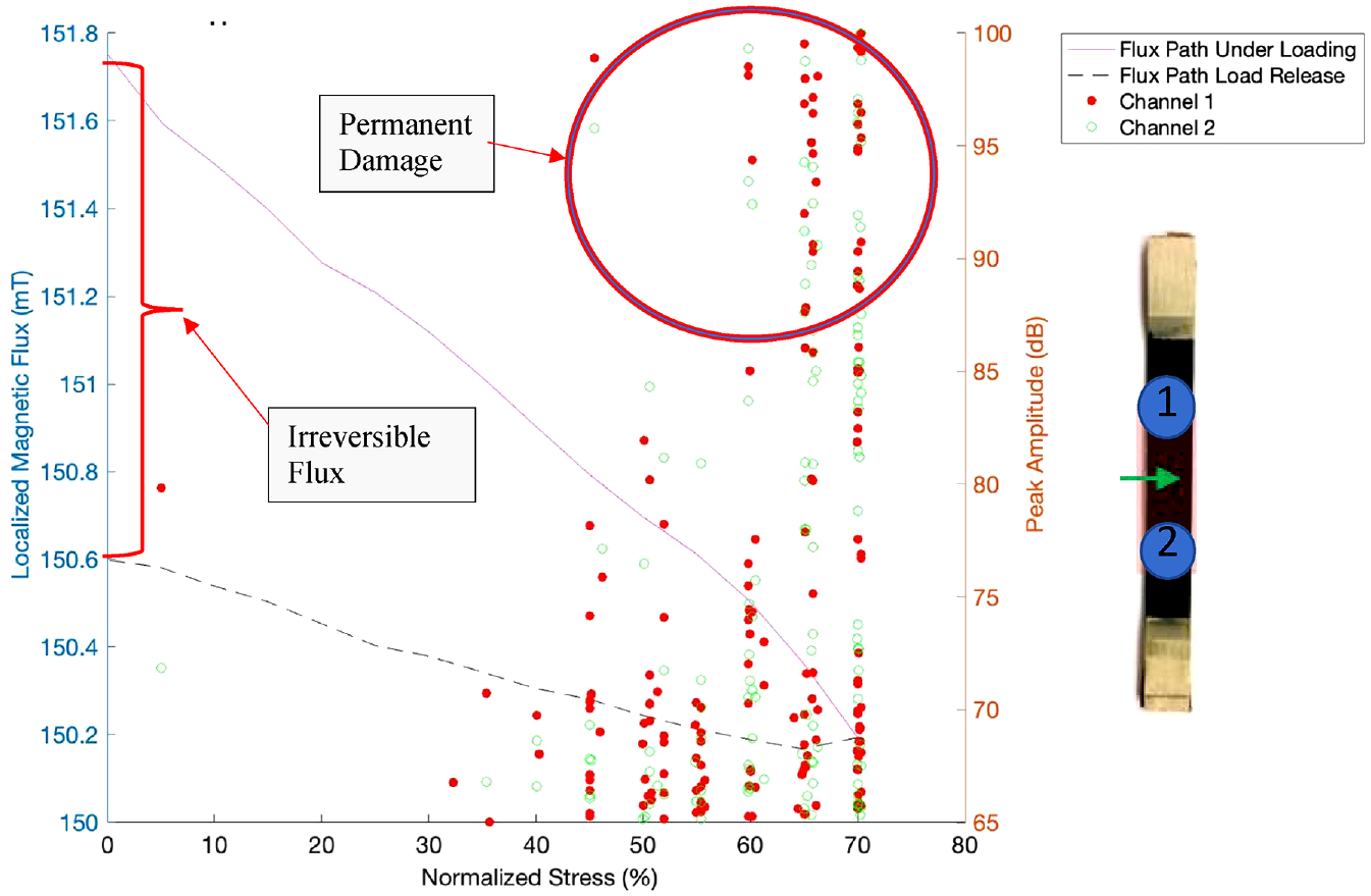
MagCFRP localized flux density versus normalized stress (0%–70% UTS) versus index (reversable flux marked).
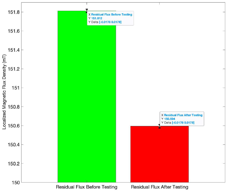
MagCFRP localized flux density before and after 0%–70% UTS mechanical testing.
As seen in Figures 16 and 17, an inverse relationship exists between applied loads and localized magnetic flux density. This response can be explained by observing the coupling between
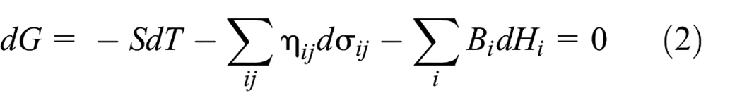
where
There was an observed jump in the localized magnetic flux at the 30% UTS load increment (associated with the left y-axis). This jump in the localized magnetic flux density is circled in red in Figure 15. With damage precursors in mind, this sudden increase in magnetic flux density response could signify a damage precursor. The hypothesis is that the sudden increase in load caused micro-cracking in the matrix material. This failure is likely explained by the Terfenol-D particles’ high conglomerate population, as seen in Figure 4 and the nominal actual comparison CT-scan in Figure 21.
Since the Terfenol-D is embedded in the matrix material, the microcracking causes a release in stress/strain surrounding the particles. This release in stress would explain the sudden jump in localized magnetic flux density, which would cause an increase in available out-of-plane magnetic energy no longer being used to do work on the particles (to maintain their shape). More experimental, analytical, and numerical studies must prove this micro-mechanical theory within the MagCFRP system.
After the 30% UTS loading increment, the inverse relationship between the localized magnetic flux density and load follows its trend. As seen in Figure 15, 100% reversible localized magnetic flux density is achieved with a maximum load of only 40% UTS. Hamann and Dahlberg (2017: 1–3) and Shanmugham et al. (2004: 267–274), suggest that irreversible changes in flux and strains are an indication that permanent damage exists. Since the maximum load was only 40% of the UTS (elastic regime), it was expected to achieve complete reversible flux.
3.3. MagCFRP magneto-plastic response results
For the plastic interphase damage response, the load increments were 5% up until 70% of the material’s UTS was achieved. The step intervals were manually controlled concerning the AE activity. When the AE “events” ceased, the load profile was increased by 5% UTS. Once 70% UTS was achieved, the load was stepped back down to 0% UTS. As seen in Figure 16, the inverse relationship between applied loads and localized flux still exists. However, 100% localized reversible magnetic flux density was not achieved (reversible magnetic flux density of only 25%).
With interfacial degradation in mind, there was an observed drop-off in the return rate of reversible flux after 70% UTS loading. This magnetic response change is a sign of permanent damage at the particle-matrix interphase and the fiber-matrix interphase. Observing this reduction in out-of-plane magnetic response is sustained by the variance of the magnetostrictive coefficient
3.4. MagCFRP acoustic emission (AE) data correlation
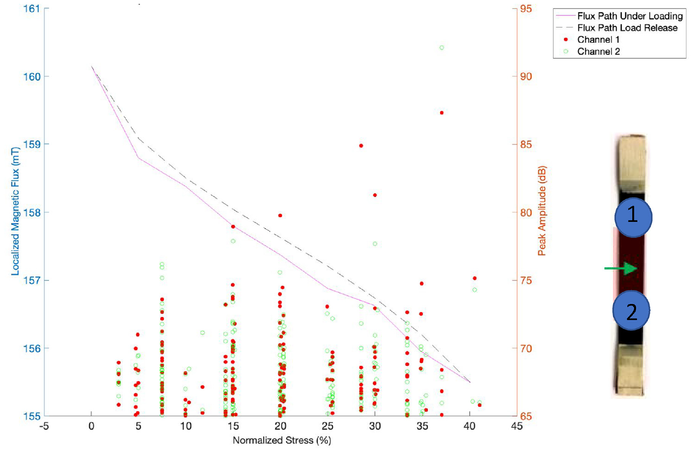
When AE is coupled with the magnetostriction sensor, there was a positive correlation between the AE event intensities and the diminished magnetostriction response. As depicted in Figures 18 and 19, the green points represent AE sensor 1, and the red points represent AE sensor 2. These AE sensors in this application are responsible for capturing acoustic wave events and their respective peak intensity in decibels (dB). The sensor-specific AE peak amplitude and localized magnetic flux density associated with each load step are captured in Figures 18 and 19.
MagCFRP localized magnetic flux density versus peak AE amplitude versus normalized stress (0%–40% UTS).
MagCFRP localized magnetic flux density versus peak AE amplitude versus normalized stress (0%–70% UTS).
The localized magnetic flux density data (left y-axis) plotted in Figure 18 was formed by averaging the magnetic response for each loading interval (x-axis) and merging the AE data (right y-axis) on those same loading intervals. As seen in Figure 15, the exact inverse relationship between localized magnetic flux density and normalized stress is illustrated in Figure 18. For the 0%–40% UTS loading interval (flux path under loading, depicted by pink line), as the stress increases, the localized magnetic flux decreases. For the 40%–0% UTS loading interval (flux path load released, depicted by the black line), the localized magnetic flux increases as the stress decreases. In the gradient of this localized flux versus normalized stress plots experimentally gives you a solution for the elastic magnetostriction coefficient
Revisiting the damage precursor assumption made in section 3.2 and Figure 14, the AE data in Figure 18 shows that at the 30% UTS load interval, there was an observed peak amplitude of 85 dB. At this dB level, mode II shear/ply delamination failure is initiated (Boshe, 2004). Although this type of defect is not what the Army would consider a precursor, it is still significant that MagCFRP locally responds to this type of damage initiation.
For a loading interval of 0%–70% UTS, as the stress increases, the localized magnetic flux decreases. However, the rate of return of the localized magnetic flux concerning the stress was significantly diminished. For the max load interval of 0%–70% UTS, the peak AE amplitude observed was more than 100 dB, as seen in Figure 19.
At this dB level, mode I and mode II fiber-matrix debonding, cracking, and shear delamination failure has been initiated and propagated (Boshe, 2004; Chang, 2013). The irreversible localized magnetic flux density is attributed to the high onset of interfacial damage in the specimen. This server level of composite damage is not what the Army would consider a damage precursor, as other traditional NDE methods could detect these defects. However, it is still significant that MagCFRP responds to this high level of damage propagation. Acknowledging that AE is a well-known and well-accepted NDE technique is essential in solidifying the capability of MagCFRP to be a valuable NDE solution for future high-stress Army CFRP aerospace components.
3.5. MagCFRP X-ray computed tomography (CT) image correlation
X-ray CT is a 3D imagining methodology that reconstructs a series of 2D X-ray images into a 3D image. X-ray CT was used as a post-processing technique to capture images of actual damage and compare them to recorded magnetostriction data. Due to highly intense beam hardening artifacts, little macro–X-ray CT information was captured about the embedded Terfenol-D particles’ damage. However, areas away from the conglomeration of particles did validate the was the severe onset of damage after a 70% UTS loading interval (fiber breakage, surface ply delamination/cracking), as seen in Figure 20.
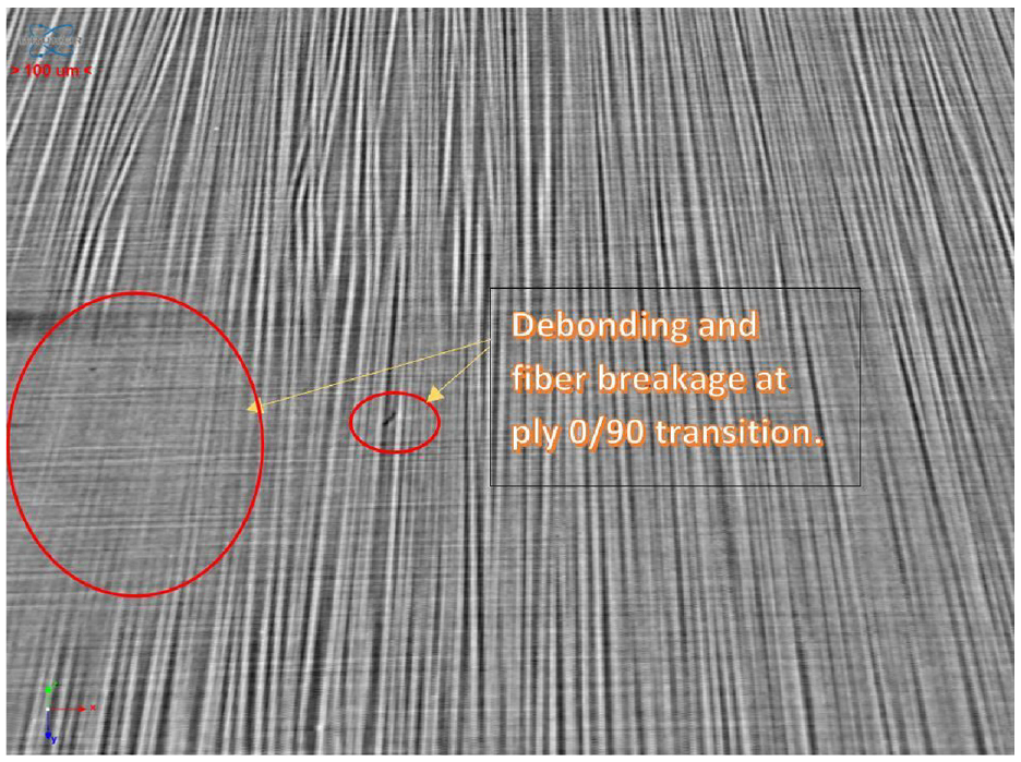
Micro X-ray CT scan of MagCFRP sample after 0%–70% UTS Tensile Testing.
Figure 21 illustrates a micro–X-ray CT post-processing technique called nominal actual comparison. Nominal actual comparison takes two images of a specimen before and after testing and measures the deformation. As seen in Figure 21, the observed deformation of the Terfenol-D conglomerates occurred predominantly at the particle-matrix interphase and did not exceed 100
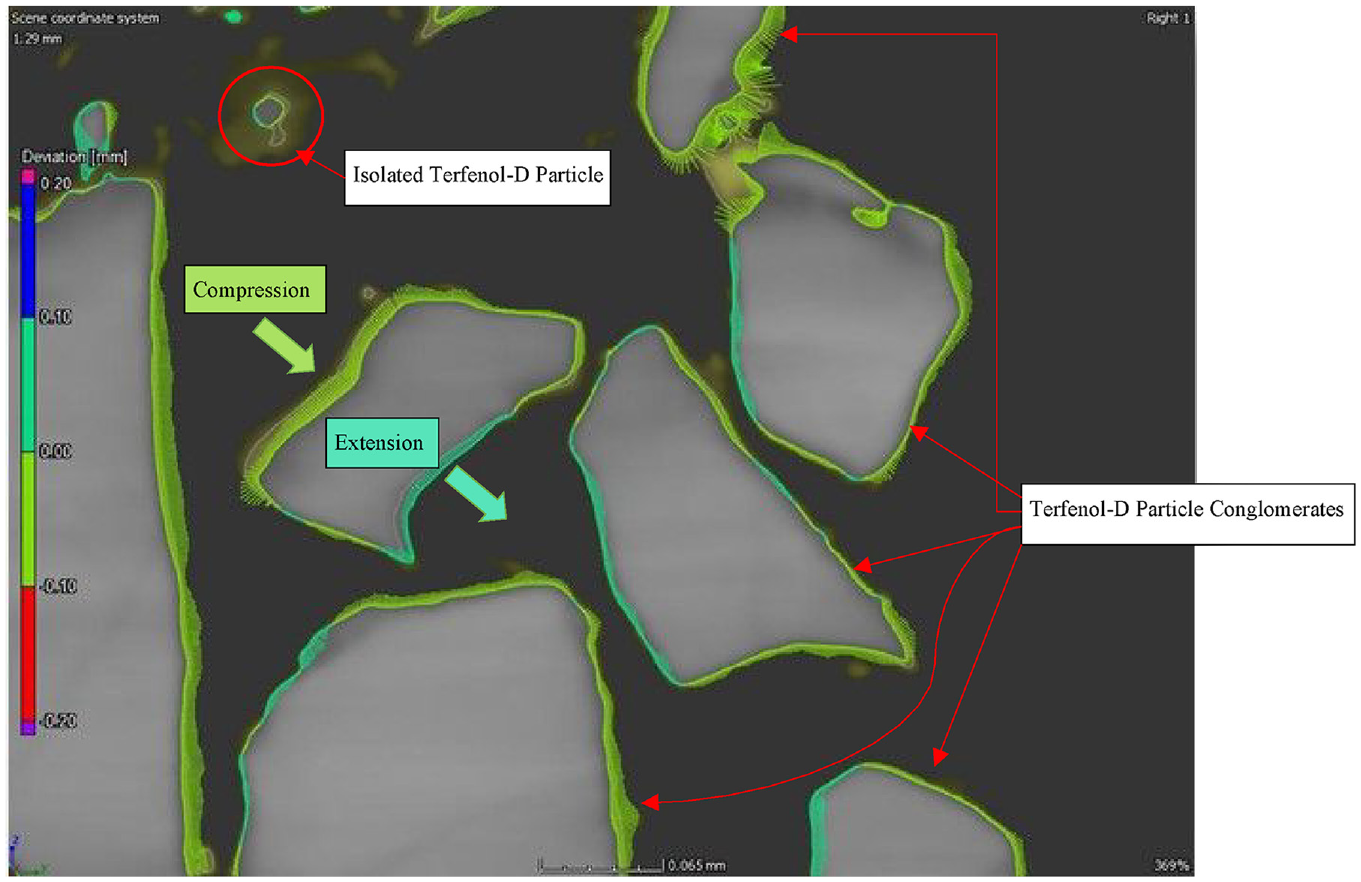
Nominal actual comparison using micro X-ray CT scan of MagCFRP post 0%–70% UTS tensile testing.
4. Conclusion
In the baseline results (CFRP specimen without embedded Terfenol-D), the average percent change from the magnetostriction sensor was only 0.02%, with a calculated first-order uncertainty of ±0.0178 mT. For the quasi-static testing procedure of specimen 15 wt.% MagCFRP on a 0%–40% loading interval of the material’s UTS, there was an observed localized (32 mm2 field of view) magnetic flux density “strain” of more than 5 mT (4%) with a reversible magnetic flux density of 100% at the localized scanning region of the MagCFRP. The observed AE data showed that microdamage initiation had occurred, and the onset of mode II failure may be associated with flux increase at 30% UTS.
For 15 wt.% MagCFRP on a loading interval 0%–70% UTS, there was an observed localized (32 mm2 field of view) magnetic flux density “strain” of more than 3 mT (2%). The experimental AE event intensity data showed that high levels of damage propagation had occurred. At these peak dB levels, the onset of mode I and II failures was associated with the irreversible magnetic flux density (only 25% reversible flux) in the MagCFRP. For the max load interval of 70% UTS, the peak amplitude observed was more than 100 dB. At this dB level, mode I and mode II fiber-matrix debonding, cracking, and shear delamination failure has been initiated and propagated (Boshe, 2004; Chang, 2013).
Figure 21 illustrates an X-ray CT post-processing technique called nominal actual comparison. Nominal actual comparison takes two images of a specimen before and after testing and measures the deformation. As seen in Figure 21, the observed deformation of the Terfenol-D conglomerates occurred predominantly at the particle-matrix interphase and did not exceed 100
As seen in Figures 15 and 16, an inverse relationship exists between applied loads and localized magnetic flux density. This response can be explained by observing the coupling between
As seen in Figure 16, although the Terfenol-D embedded material was stressed to 70% UTS, the inverse relationship between applied loads and localized magnetic flux density still exists. However, the reversible magnetic flux density of 100% on the 0%–40% UTS interval was not achieved at the localized MagCFRP scanning region on the 0%–70% UTS interval. With interfacial degradation in mind, one would expect a drop-off in the return rate of reversible localized magnetic flux density after the 0%–70% UTS loading interval. This change in magnetic response is a sign of permanent damage at the particle-matrix interphase and the fiber-matrix interphase. Observing this reduction in out-of-plane magnetic response is sustained by the variance of the magnetostrictive coefficient
Though the end goal may be to detect early damage propagation in real-time using embedded magnetostriction techniques, one takeaway from this current research is that the observed magnetostrictive response can determine the instantaneous level of stress and strain that the material is currently experiencing and has experienced. For example, in Figures 14 to 19, there is a direct correlation between in-plane stress and localized out-of-plane magnetic flux density. This information could be further used to define the instantaneous state of stress in the material and the fatigue life of CFRPs. The MagCFRP sample reported in this work yields the clearest results from this round of testing. Because these scans are taken on a localized scale, not a full scale, the magnet signature will vary depending on the gauge area scanning region. The deposition technique used in this study does not yield homogeneous distribution of Terfenol-D micro-particles between the CFRP plies. Future work includes advanced particulate deposition techniques such as sputtering and field-structured magnetoelastomers.
MagCFRP has shown promising results for NDE with implications to use in SHM applications. In time, with manufacturing and testing improvements, there is evidence that MagCFRP could play a vital role in real-time CFRP dislocation density propagation for the US Army’s future vertical lift vehicles and weapons systems. Plans for future fabrication techniques include implementing new deposition techniques (e.g. well-mixed particulate slurry for B-stage fabrication, sputtering deposition, etc.) for embedding Terfenol-D into the CFRP matrix to ensure a more uniform magnetostrictive material distribution. This will allow for consistency between experimental and numerical geometries. Thus, yielding more accurate results.
The future work plans for this research include increasing and decreasing the weight percent of the deposited Terfenol-D embedded in the CFRP to seek a more robust magnetostriction response without compromising the structural integrity of the composite. With increasing the weight percent of Terfenol-D content in the CFRP by 5%–10%, there comes a risk of compromising the structural integrity of the carbon fiber part. More work will also include the implementation of a fatigue testing protocol to ensure that the parts are not prone to catastrophic fatigue failure. By measuring and quantifying the differences between a pristine baseline specimen and a fatigued specimen, crack density propagation could be quantified. There are also plans to use the MagCFRP as a data source for AI and ML SHM schemes. AI and ML schemes must be implemented to drive real-time data processing. Post-processing of the MagCFRP is the most laborious component of this research. Future aspirations to model the phenomena using a multi-physics FEA platform and coarse grain molecular dynamics (MD) simulations are also pursued. Composite constituent thermal expansion behavior must also be studied before MagCFRP can be used in high-temperature military applications.
MagCFRP has the characteristics and capability to be used in various NDE and SHM applications. Due to the smart material (Terfenol-D) being embedded within the matrix of traditional pre-preg CFRPs, a wide range of application-specific materials can be rapidly designed and manufactured for the US Army’s future vertical lift vehicles. MagCFRP governing magnetostriction capability will allow the material architecture to be used in non-contact damage detection environments. This unique material design promotes sustainability within the design and engineering of Army vertical lift vehicles. Not only will MagCFRP be useful for future Army vertical lift vehicle designs, but it can also be retrofitted for current and past material systems. MagCFRP is truly an advancement in responsive composite materials. This research has shown that MagCFRP can be a viable solution for non-contact interphase NDE with SHM implications for future Army vertical lift composite structures.
Footnotes
Acknowledgements
The views and conclusions contained in this document are those of the authors and should not be interpreted as representing the official policies; either expressed or implied, of the Army Research Laboratory or the U.S. Government. The U.S. Government is authorized to reproduce and distribute reprints for Government purposed notwithstanding any copyright notation herein.
Declaration of conflicting interests
The author(s) declared no potential conflicts of interest with respect to the research, authorship, and/or publication of this article.
Funding
The author(s) disclosed receipt of the following financial support for the research, authorship, and/or publication of this article: Research was sponsored by the Army Research Laboratory and was accomplished in Cooperative Agreement Number W911NF-19- 2-0343.