
Abstract
A novel high performance multi-walled carbon nano-polyvinylpyrrolidone/silicon-based shear thickening fluid (MWCNTs-PVP/SiO2-STF), abbreviated and subsequently referred to as MPS-STF, is developed in this paper. The rheological properties of the MPS-STF are investigated, and the viscosity model of MPS-STF is established. Furthermore, the MPS-STF based viscous fluid damper (MPS-STF-VFD) is designed according to the rheological characteristics of the novel fluid. The impact of loading frequencies, displacement amplitudes and the numbers of piston holes on the dynamic performance of the damper is studied through sophisticated multiple cases loading tests using MTS facility. The test results show that the loading frequency, displacement amplitudes and the number of piston holes have great influence on the rheological properties of MPS-STF. This directly affects the maximum damping force and heat dissipation capacity of MPS-STF-VFD. Finally, the mechanical model of the damper is established based on the principle of fluid mechanics. The simulation results agree well with the experimental data. The high damping performance of the MPS-STF-VFD can be achieved based on the characteristics of the modified fluid. Relevant results reported in this paper can provide an important solution for the development and application of damping technology in engineering structures.
Keywords
1. Introduction
Viscous fluid damper is a passive control device (Biswal et al., 2022; Khedmatgozar Dolati et al., 2021; Rajeswaran and Wijeyewickrema, 2022; Zhou et al., 2016). Its basic principle is that the fluid inside the damper generates throttling resistance through a specific hole or device clearance and then dissipates the energy input to the damper from the outside. Viscous dampers made according to the characteristics of fluid materials often have high energy consumption (Abdi et al., 2016; Jiao et al., 2021; Lim and Kim, 2020; Ma et al., 2020). Therefore, the choice of fluid material has a very important influence on the energy dissipation and vibration reduction of viscous damper. Shear thickening fluid (STF) is a new smart material capable of generating viscosity response through changes within its own critical fluid rate (Bossis et al., 2021; Sun et al., 2021, 2023b; Wei et al., 2020). Mahesh et al. (2022) impregnated jute fabric with shear thickening solution made of silica with different mass percentages. It was found that the energy absorption of nano-silica composites increased with the increase of nano-silica particles. Nakonieczna et al. (2019) added a small amount of multi-walled carbon nanotubes to the silicon-based shear thickening solution to change its rheological properties. The impact test of the modified shear thickening fluid was carried out. The experimental results show that multi-walled carbon nanotubes can effectively combine with amorphous silica to form protective structures. The structure can efficiently absorb external energy input. Liu et al. (2017) modified nano-SiO2 with polyethylene pyrrolidone with an average molecular weight of 30 to enhance the shear thickening performance. The experiment provided a new method for the study of controllable rheology. In recent years, many domestic and foreign scholars have also studied dampers made of different viscoelastic materials (Dadkhah and Mohebbi, 2019; Hazaveh et al., 2017; Nurchasanah and Harnadi, 2021; Sun et al., 2023a; Yi et al., 2018). Zhu et al. (2020) developed a self-resetting viscous damper, which is composed of a velocity dependent system and a displacement dependent system. They also analyzed the hysteretic performance of the damper by low cyclic loading test. The hysteretic loop of the damper was full and it can operate at a wide range of frequencies. Le et al. (2020) used the iterative method to derive the iterative form of the damping ratio of the damper when the cable has a rotational constraint on the position of the viscous damper, and analyzed the influence of the rotational constraint on the damping effect of the viscous damper. Wu et al. (2020) arranged a viscous damper at the beam-column joint of steel structure and replaced part of the support to explore the influence of the damper on the seismic performance of the specimen. The experimental results showed that the hysteresis loop of the specimen with viscous damper was fuller than that of the ordinary specimen. In the plastic stage of the specimen, the energy dissipation performance of the specimen with viscous damper was better. Javidialesaadi and Wierschem (2019) designed a viscous damper with unidirectional moment of inertia, and presented its action mechanism and dynamic model. By comparing with the traditional moment of inertia damper, the new viscous damper significantly changed the resonant frequency of the system under both zero and non-zero damping conditions. Del Gobbo et al. (2018) explored the overall seismic resistance of the frame structure through different arrangements of viscous dampers. The simulation results showed that the single damper arrangement cannot meet the requirements of the optimal engineering parameters for the interlayer displacement and acceleration of the structure.
In summary, some scholars have explored the effect of the arrangement of viscous dampers on the overall vibration and energy dissipation of the structure under different application conditions. Others have improved the performance of the viscous damper by improving the viscoelastic material inside the damper or changing the structure of the damper. However, there are few researches on the preparation of materials with high damping characteristics and the design of viscous dampers for damper performance test. Therefore, this paper will prepare a shear thickening fluid with high damping characteristics, and design a new MPS-STF-VFD according to the material characteristics to explore its mechanical properties.
2. Preparation and characterization of shear thickening fluid
Within a certain range of shear rate, shear thickening fluid has the characteristic of highly nonlinear increase of its own viscosity with the increase of shear rate (Dixit et al., 2019; Kośla et al., 2020; Oliva-Lamarca et al., 2019; Wei et al., 2019; Yeh et al., 2019). Shear thickening fluid can well consume the energy input and reduce the structural vibration caused by the energy input. Therefore, a high-damping shear thickening fluid is prepared in this paper. The rheological properties of the fluid are investigated and the viscosity model of STF thickening interval is obtained by numerical simulation.
2.1. STF preparation
Nanosilica powder with an average particle size of 12 nm was purchased from the Chinese Chemical Company Reckitt Benckiser. Polyethylene glycol PEG200 was purchased from Shandong Yousuo Chemical Technology Co., Ltd, China. Its hydroxyl value is 510–623 mg KOH/g, and it is a stable transparent liquid at room temperature. Polyvinylpyrroxanone (PVP) with a pale yellow powder appearance was purchased from Xilong Science Co., Ltd. Multi-walled carbon nanotubes (MWCNTs) with a black powder appearance were purchased from China Hengqiu Nano Reagent Co., Ltd. Its inner diameter is 2–6 nm, outer diameter is 9–18 nm, and length is 3–12 μm. All chemical reagents were purchased from commercial sources and used without further purification.
Before preparing the MPS-STF system, put SiO2 particles, multi-walled carbon nanotubes (MWCNTs) in a vacuum dryer and dry for 24 h at 80°C to remove moisture. Then put 200 ml of PEG200 and the corresponding mass of MWCNTs powder into the beaker, mechanically mixed to uniform. During the mixing process, gradually add SiO2 and polyvinylpyrrolidone (PVP) powder according to the requirements of the different mixing ratios of the MPS-STF system, repeating the above-mentioned mixing procedure. After the material in the beaker appears completely uniformly black, the beaker is placed in the ultrasonic washer for 20 min until the mixed nanoparticles are evenly dispersed in the PEG200. Finally, to ensure that the composite material disperses evenly without bubbles during the preparation process, the prepared samples are placed in the ultrasonic cleaner for ultrasonic resonance 1 h. It is then placed in a vacuum dryer. Finally, MWCNTs-PVP/SiO2-STF(MPS-STF) with PVP mass fractions of 0.00%, 0.05%, 0.10%, 0.15%, 0.20%, and 0.25% are obtained. Figure 1 shows the MPS-STF preparation process.
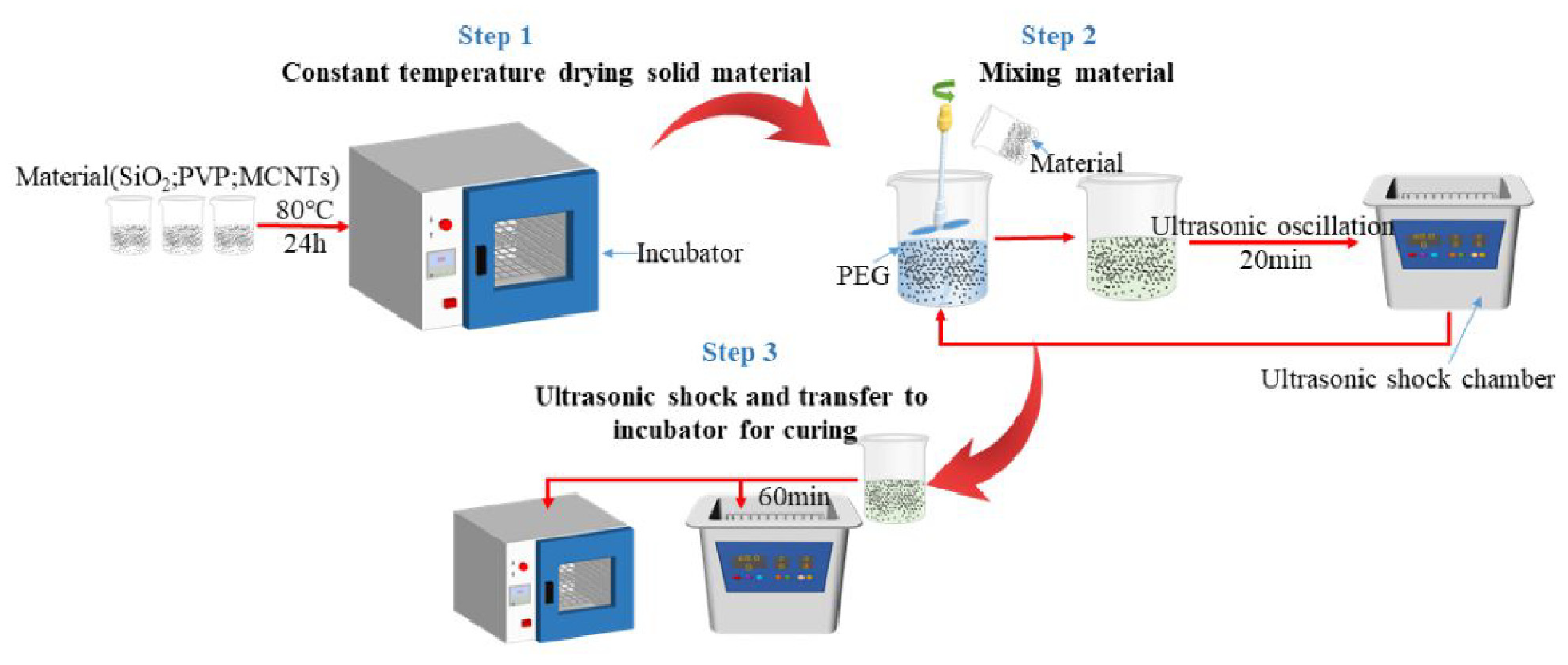
MPS-STF preparation process map.
2.2. Rheological test
The AR2000 rheometer from American TA Company is used to test the steady-state and dynamic flow performance of MPS-STF with different mixing ratios. Each group of materials (approximately 200 ml) is randomly selected from five locations in the corresponding beaker for sampling and testing. Each sampling material is about 5 ml. The five test loops obtained from the rheological test of each group of materials are basically the same. The data used in the experimental loop in the article has been averaged. The diameter of the plate rotor is 30 mm, and the distance between the plates is 1 mm. The specific tests are as follows: Under the conditions of a temperature of 25°C and a shear rate sweep range of 0.1–1000 s−1, a steady-state rheological test of MPS-STF with different mixing ratios is performed.
2.3. STF characteristics analysis
The performance of MPS-STF with different mix ratio is tested by AR2000 rheometer. With the change loops of shear viscosity and shear rate of MPS-STF with different PVP mass fraction ratios at the shear rate scanning range of 0.5 mm plate spacing and 0.1–1000 s−1, we adopted the test results of Sun et al. (2021). The effects of shear thickening effect and peak viscosity rate interval are considered. Compared with STF without PVP, the peak viscosity of MPS-STF with 0.10% PVP mass fraction increase from 118.993 to 216.750 Pa·s, an increase of 82.15%, and the shear thickening effect is obvious. In addition, the peak viscosity rate parameter range of 0.1% MPS-STF is 40.65–102.1 s−1, which can meet the requirements of STF to maintain excellent energy dissipation under a wide range of rates. Therefore, the damping fluid used in the damper is 0.1% MPS-STF.
Sun et al. (2021) found that the steady-state rheological properties of 0.1% MPS-STF at different plate spacing, in which the shear thickening solution had the best shear thickening effect when the plate spacing was 1 mm. Since 0.1% MPS-STF is a non-time-dependent non-Newtonian fluid, it can be represented by the constitutive model of power law fluid. The rheological index n of STF is 1.245.
Figure 2 shows a numerical simulation of 0.1% MPS-STF at 1 mm plate spacing. The STF viscosity model is as follows:
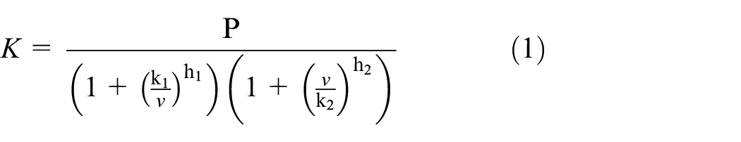
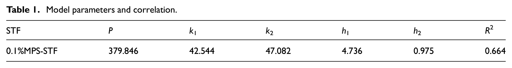
Where K is the apparent viscosity and v is the shear rate. Where P, k1, k2, h1, and h2 are relevant parameters (Table 1).
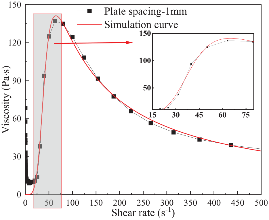
Comparison of STF test curve and simulation curve at 1 mm plate spacing.
Model parameters and correlation.
3. Structural design of the MPS-STF-VFD
Viscous fluid damper is a passively controlled vibration reduction device whose internal structure is compatible with the rheological characteristics of energy dissipating materials (Fu et al., 2018; Huang et al., 2019; Moslehi Tabar and De Domenico, 2020; Qin et al., 2017; Sun et al., 2018; Wei et al., 2018). This can effectively improve the energy dissipation effect of the damper. A new damper is designed using 0.1% MPS-STF rheological data. The diagram of the STF viscous damper (MPS-STF-VFD) is shown in Figure 3, where the length of the cylinder cavity is 200 mm, the diameter of the cavity is 60 mm, the thickness of the cylinder cavity wall is 9 mm, the diameter of the piston is 59 mm, and the diameter of the piston rod is 12 mm.
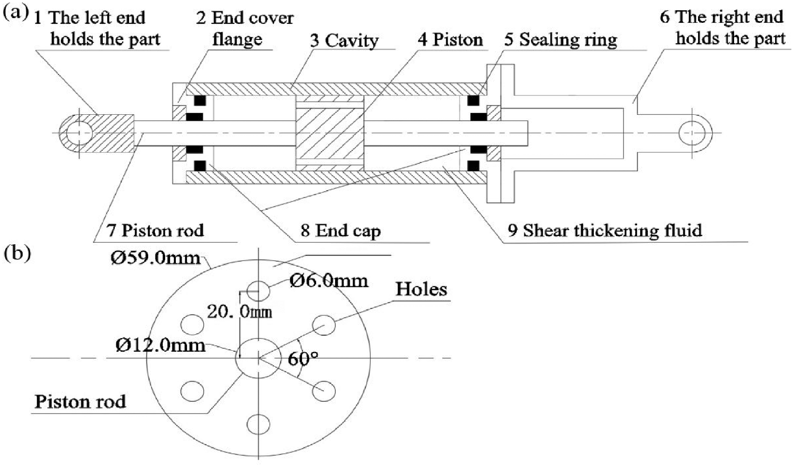
MPS-STF-VFD: (a) schematic diagram of MPS-STF-VFD and (b) position of piston holes.
Reserve six holes in piston. The hole diameter is 6 mm, and the preset piston movement interval is [−30 mm, 30 mm]. All parts of the damper are made of Q345 steel. The possible leakage of shear thickening fluid when working in viscous dampers is considered. Therefore, the end cover flange and sealing rubber ring are arranged on both sides of the sealing cover port.
4. Performance test of the MPS-STF-VFD
The loading test of the new damper is conducted by MTS (as shown in Figure 4) (Hazaveh et al., 2020; Jamshidiha and Yakhchalian, 2019; Janbazi Rokni and Tabeshpour, 2019; Li et al., 2020; Noruzvand et al., 2020). Before the initial loading, the damper is preloaded. This ensures STF on both sides of the piston and no deviation of the damper during reciprocating motion. During the test at room temperature of 25 ± 1°C, the loading test adopts sinusoidal displacement loading control mode. The effects of displacement amplitude, loading frequency and the number of piston holes on the performance of MPS-STF-VFD are investigated. The damper was loaded under nine working conditions, and each loading case consists of 7 round-trip. After each loading case, load the damper again at an interval of 10 min to ensure that the shear thickening fluid settles in a relatively stable situation.
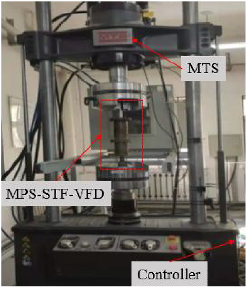
MTS loading device.
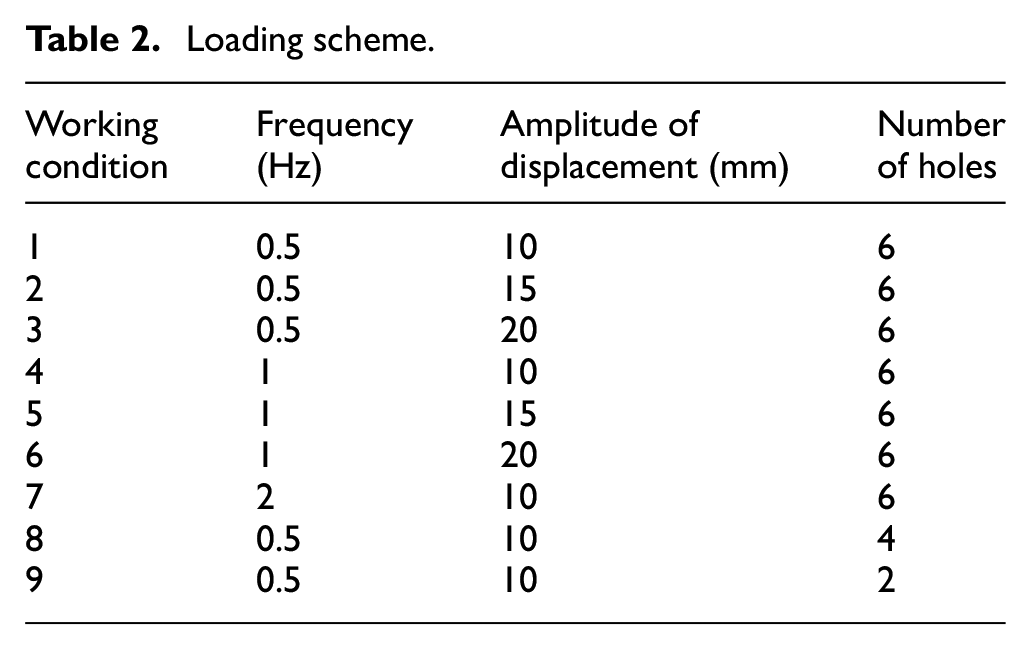
The loading scheme has nine working conditions. The influence of frequency on the performance of the damper is analyzed through working conditions 1, 4, and 7. The influence of the displacement amplitude on the performance of the damper is analyzed by working conditions 1, 2, 3, 4, 5, and 6. The influence of the number of piston holes on the performance of the damper is analyzed by working conditions 1, 8, and 9. Check the leakage condition of the damper after each set of working conditions is completed. If there is no leakage, continue the test. The specific test loading scheme is shown in Table 2.
Loading scheme.
5. Experimental results and analysis
In this paper, the mechanical properties of viscous dampers are prescribed in “Dampers for Vibration Energy Dissipation of Building” (JG/T 209-2012) (JG/T 209-2012, 2012).The mechanical properties of MPS-STF-VFD under the above loading scheme are reflected by damping force
(1) Single cycle energy consumption
(2) The equivalent secant stiffness K can be expressed as

Where
(3) Equivalent damping ratio

In addition, according to the relevant provisions of the “Dampers for Vibration Energy Dissipation of Building” (JG/T 209−2012) on the mechanical properties of the viscous dampers, the trial of each condition of viscous dampers conducted 5 cycles in a row, and the data of the third hysteresis loop was used as the measured value of the test.
5.1. Frequency correlation performance test
As shown in working conditions 1, 4, and 7 in Table 2, the mechanical properties of MPS-STF-VFD are explored by controlling the loading frequency.
Typical hysteresis loops of MPS-STF-VFD at certain frequency is shown in Figure 5. Figure 5(a) shows the hysteresis loop related data of MPS-STF-VFD when the loading frequency is 0.5 Hz. Taking Figure 5(a) as an example, hysteretic loops of MPS-STF-VFD at different loading frequencies are obtained by selecting five consecutive groups of hysteretic loop data for comparative analysis, as shown in Figure 5(b). When the loading frequency is 0.5 and 1 Hz, the hysteresis loops of MPS-STF-VFD are relatively full, and the energy dissipation performance is better. However, when the loading frequency reaches 2 Hz, the hysteresis loop of MPS-STF-VFD appears pinch, which is not conducive to the energy dissipation of the damper. As can be seen from Figure 5(b), the speed of the piston is minimum when it moves near the maximum displacement. MPS-STF is in a state of shear thinning and has a large viscosity at a small shear rate, which makes the damper have a certain damping force near the maximum displacement. As the piston speed increases, MPS-STF changes from shear thinning state to shear thickening state. As a result, the viscosity of MPS-STF increases and the hysteresis loop of MPS-STF-VFD is relatively full. However, as the loading frequency increases to 2 Hz, the piston speed changes faster and the damping force changes significantly. Moreover, when the maximum speed of the piston exceeds the shear rate corresponding to the peak viscosity of MPS-STF, the damping force of MPS-STF-VFD decreases and the hysteretic loop appears to pinch.
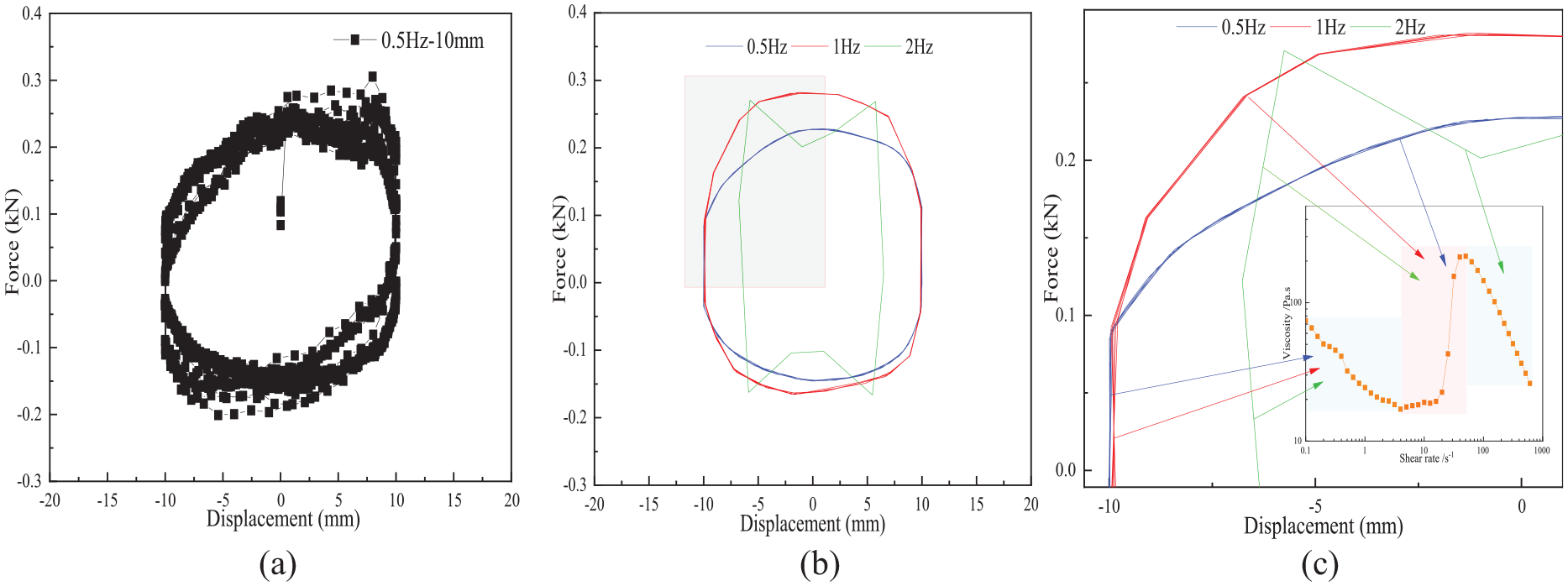
Hysteretic loop of MPS-STF-VFD at different loading frequencies and its relation with the changes of fluid characteristics of MPS-STF: (a) hysteresis loop of MPS-STF-VFD at 0.5 Hz, (b) hysteretic loops, (c) hysteretic loops with the changes of fluid characteristics of MPS-STF.
It can be seen from Figure 6 that the dissipated energy and maximum damping force of MPS-STF-VFD show a trend of change that increases after decreases. The reason is that when the loading frequency is 0.5 and 1 Hz, the maximum motion speed of the piston does not exceed the shear rate corresponding to the peak viscosity of MPS-STF, and the MPS-STF is in the thickening stage as a whole. The reason is that when loading frequencies are 0.5 and 1 Hz, the maximum speed of the piston does not exceed the shear rate corresponding to the peak viscosity of the MPS-STF, and the whole MPS-STF is in the thickening state. Therefore, the dissipated energy and the maximum damping force of MPS-STF-VFD can increase with the increase of loading frequency. However, as the loading frequency increases to 2 Hz, the excessive piston speed leads to the decrease of MPS-STF viscosity, reduction in the dissipation energy of the damper, and no noticeable change in maximum resistance. This indicates that the rheological properties of MPS-STF have a greater influence on the dissipative energy of MPS-STF-VFD, but a lesser influence on its maximum damping force.
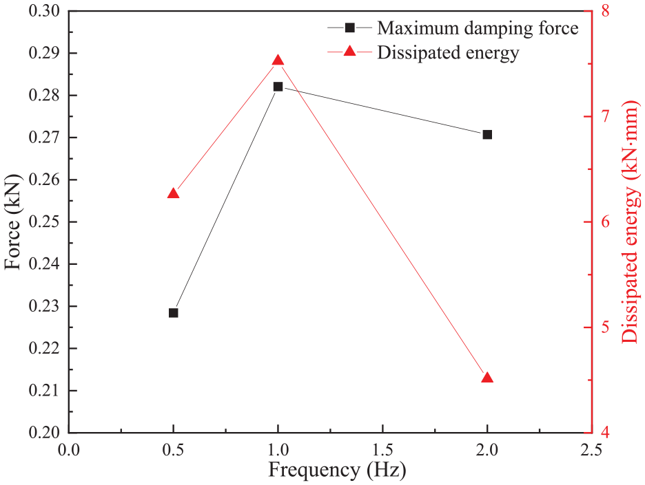
Mechanical properties of MPS-STF-VFD at different loading frequencies.
5.2. Displacement amplitude correlation test
When the loading frequency is 0.5 and 1 Hz, hysteresis loops of MPS-STF-VFD at different displacement amplitudes are shown in Figure 7(a) and (b) respectively, and correspond to working conditions 1–6 in Table 2.
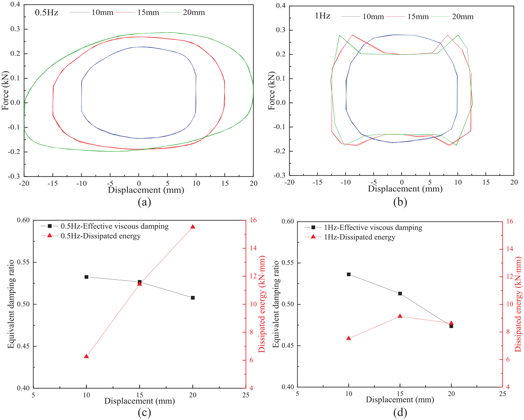
Hysteresis loop and mechanical property parameters of MPS-STF-VFD at different displacement amplitudes: (a) hysteresis loop of damper at 0.5 Hz, (b) hysteresis loop of damper at 1 Hz, (c) mechanical property parameters of damper at 0.5 Hz, and (d) mechanical property parameters of damper at 1 Hz.
As can be seen from Figure 7(a), when the loading frequency is 0.5 Hz, hysteresis loops of MPS-STF-VFD are relatively full with the increase of displacement amplitude. In addition, when the displacement amplitude increases from 10 to 15 mm and 20 mm successively, the growth trend of the maximum damping force of MPS-STF-VFD decreases. This indicates that although MPS-STF is in the thickening state, the thickening effect decreases with the increase of displacement amplitude. As shown in Figure 7(b), when the loading frequency is 1 Hz and the displacement amplitude is 10 mm, the hysteresis loop of MPS-STF-VFD is relatively full, but the other two hysteresis loops show pinch phenomenon. Especially when the displacement amplitude is increased to 20 mm, MPS-STF-VFD cannot reach the preset maximum displacement, and the hysteretic loop pinch is more serious. It can be seen from the maximum displacement of each hysteresis loop that the lifting speed of damping force increases with the increase of displacement amplitude. This phenomenon indicates that MPS-STF is more likely to reach the thickening state when the displacement amplitude is larger.
As can be seen from Figure 7(c), when the loading frequency is 0.5 Hz, the dissipated energy of MPS-STF-VFD increases with the increase of displacement amplitude, but the variation trend of equivalent damping ratio is opposite. In addition, Figure 7(d) reflects that when the loading frequency is 1 Hz, the influence of increasing displacement amplitude on the energy dissipation capacity of MPS-STF-VFD gradually decreases, and the equivalent damping ratio shows a downward trend.
5.3. Piston hole number correlation performance test
The number of holes in the piston has a direct effect on the speed of MPS-STF passing through the piston. Therefore, the test explored the mechanical properties of MPS-STF-VFD by controlling the number of piston holes, as shown in Figure 8(a).
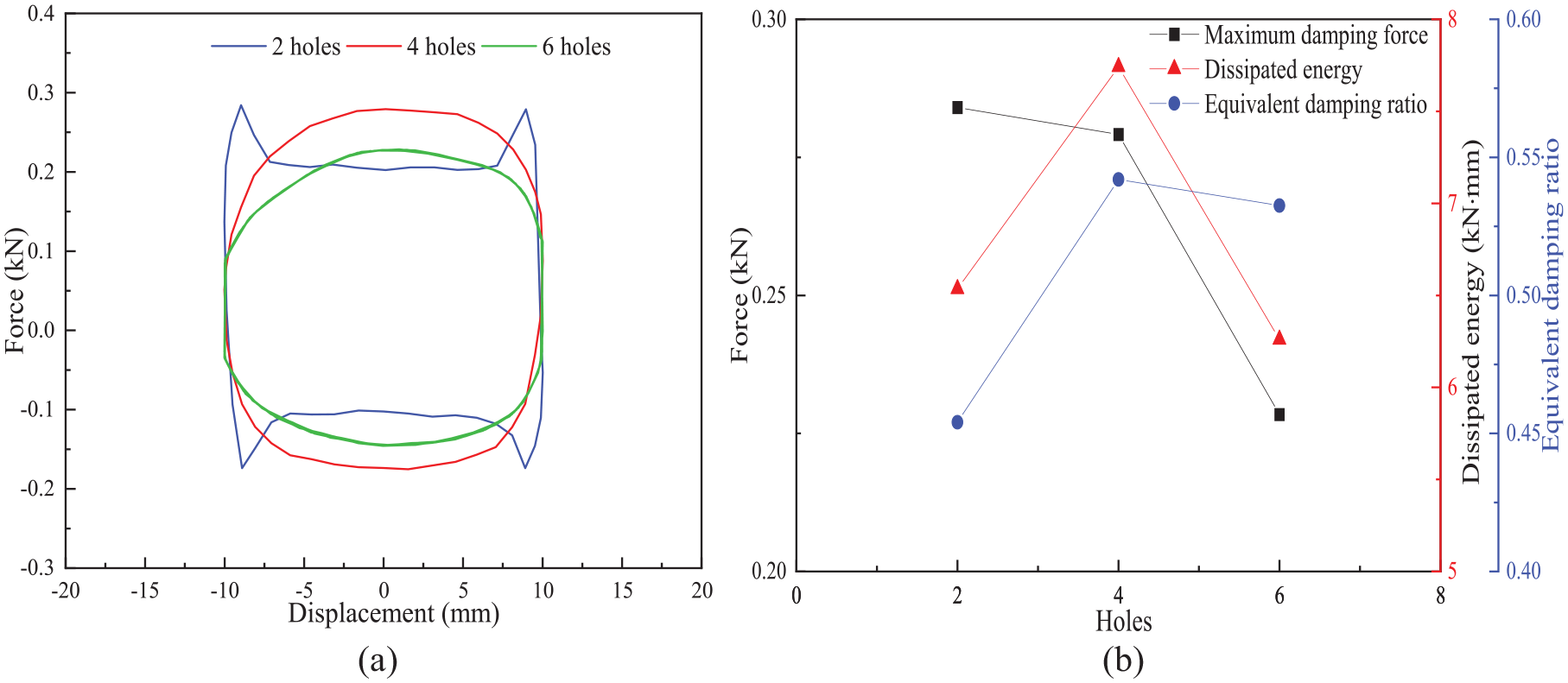
Hysteretic loop and mechanical property parameters of MPS-STF-VFD with different number of piston holes: (a) hysteretic loop and (b) mechanical property parameters.
Figure 8(a) shows hysteretic loops of MPS-STF-VFD at different number of piston holes, corresponding to conditions 9, 8, and 1 in Table 2. As shown in Figure 8(a), with the continuous increase of the number of holes in the piston, the change of damping force at the point of maximum displacement slows down significantly. Especially when the number of piston holes is two, the hysteresis loop appears pinch phenomenon. This phenomenon indicates that the maximum piston speed has exceeded the shear rate corresponding to the peak viscosity of MPS-STF, and MPS-STF is in a state of shear thinning. As can be seen from Figure 8(b), with the increase of the number of piston holes, the maximum damping force of MPS-STF-VFD decreases successively, while the energy consumption and equivalent damping ratio both increase first and then decrease. This indicates that when the piston hole is four, the energy dissipation effect of MPS-STF-VFD is relatively good.
6. Numerical analysis of MPS-STF-VFD
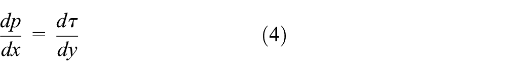
According to the basic principle of fluid mechanics, the mechanical model of the MPS-STF-VFD damper is established by deducing the relation between the damping force and the shear rate of STF. In Figure 9, h is the plate spacing, L is the plate length, and
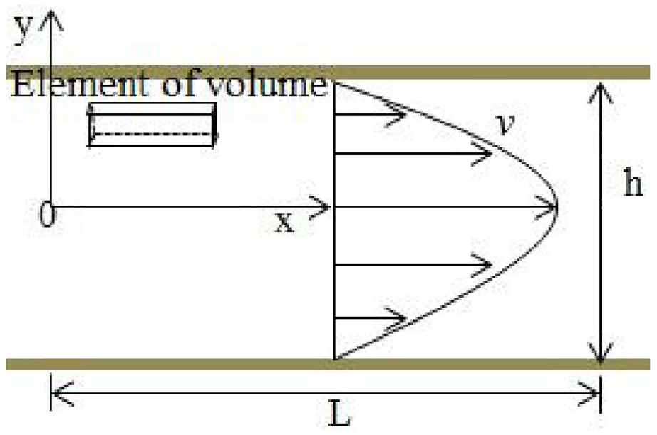
Schematic diagram of the flow field of the plate.
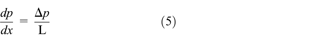
The mechanical equilibrium equation of a micro element in the x direction can be expressed as
When the width of the piston is small, the pressure at both ends can be expressed as
Since the flow velocity of the fluid in the spacing between the plates is symmetrical, it can be expressed as
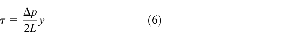
The shear stress of MWCNT-PVP/
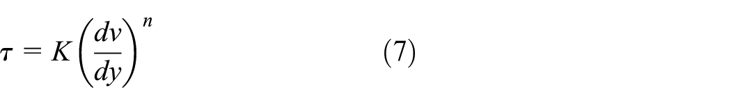
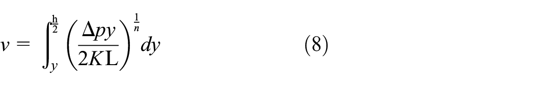
K is the apparent viscosity of STF, n is the rheological index, and v is the flow rate of STF. By substituting equation (6) into equation (7) for integration and obtaining v = 0 from the boundary condition y = h/2, the following equation can be derived
Since the flow rate of STF is called the distribution with the middle line between plates as the symmetric face, the flow through the clearance can be divided into two parts
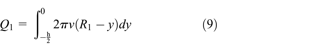
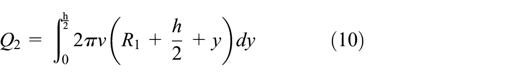
Where
Similarly, the flow through the pore is
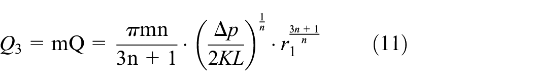
Where,
Therefore, the total flow through the clearance and piston pores is

According to the fluid continuity equation, the flow through the clearance and piston pores is equal to the flow through any section of the damper. Then the traffic relationship can be expressed as

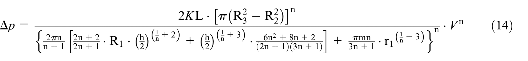
Therefore, by analyzing the structural parameters of the damper, the mechanical model of the damper can be expressed as
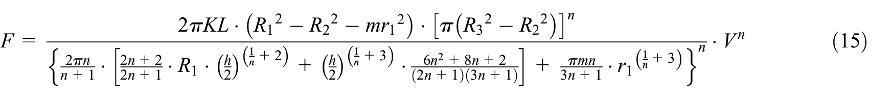
F is the damping force,
The damper structure setting parameters and loading parameters of the above three kinds of comparison tests are input into equations (1) to (15) to obtain the corresponding force-displacement loops. All the calculated results are compared and verified with corresponding test results.
Figure 10 shows the comparison between simulation results and test results of MPS-STF-VFD under different working conditions. It can be seen from the figure that when the maximum piston speed does not exceed the shear rate corresponding to the peak viscosity of MPS-STF, the test results are close to the simulation results, as shown in Figure 10(a), (b), (d), (e), and (h). However, when the maximum piston speed exceeds the shear rate corresponding to the peak viscosity of MPS-STF, that is, MPS-STF is in the shear thinning state, there is a certain error between the test results and the simulation results, as shown in Figure 10(c), (f), (g), and (i). The reason is that the piston cannot reach the preset displacement amplitude due to the fast loading speed of the test, and the simulation results cannot effectively reflect the thinning state of MPS-STF, resulting in a certain error between the test results and the simulation results.
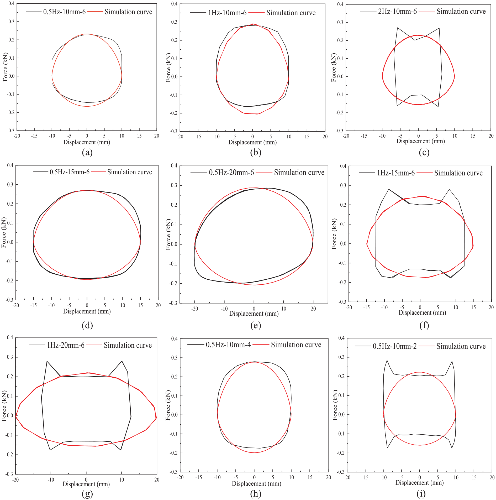
Comparison of simulation results and experimental results of MPS-STF-VFD: (a), (b), and (c) show the comparison between simulation and experimental results of the damper at different frequencies. (a), (d), and (e) show the comparison of simulation and test results of the damper with different displacement amplitudes at 0.5Hz. (b), (f), and (g) show the comparison of simulation and test results of the damper with different displacement amplitudes at 1Hz. (a), (h), and (i) show the comparison between simulation and test results of dampers with different numbers of piston holes.
7. Conclusion
Firstly, a novel high damping shear thickening fluid solution is prepared. It exhibits the characteristics of high damping and fast response. Secondly, a viscous damper based on the MPS-STF is developed. In addition, MTS is used to conduct mechanical performance tests to investigate the effect of loading frequency, displacement amplitude and the number of piston holes for the MPS-STF-VFD. Finally, the mechanical model of MPS-STF-VFD relating the damping force and loading velocity is constructed. The hysteresis loops of MPS-STF-VFD at different working conditions are simulated and compared with the test results. The main conclusions can be achieved as follows:
(1) Based on the shear thickening effect of STF and the shear rate corresponding to the peak viscosity, MPS-STF with a PVP mass fraction of 0.10% was selected as the damping material of MPS-STF-VFD. And the optimal plate spacing of STF was measured. The viscosity model of MPS-STF was obtained by simulating and analyzing the test data, which can provide reference for the design of MPS-STF-VFD.
(2) Under the condition that the displacement amplitude and the number of piston holes are fixed, the loading frequency has positive excitation effect on MPS-STF-VFD. When the loading frequency is 0.5 and 1 Hz, the hysteresis loop of MPS-STF-VFD is relatively full. However, when the loading frequency is increased by 2 Hz, the hysteresis loop of MPS-STF-VFD appears pinch phenomenon, and the energy dissipation effect decreases.
(3) Under the condition that the loading frequency and the number of piston holes are fixed, the displacement amplitude has great influence on the energy dissipation and vibration reduction of MPS-STF-VFD. When the displacement amplitude increases from 10 to 15 mm and 20 mm, the equivalent damping ratio of MPS-STF-VFD decreases gradually. At the same time, the energy dissipation efficiency of the damper is also related to the loading frequency. The higher the loading frequency, the faster the energy dissipation efficiency of the damper decreases.
(4) The number of holes in the piston is negatively correlated with the internal STF shear rate. The less the number of piston holes of MPS-STF-VFD, the higher the flow rate of MPS-STF per unit time, and the obvious change of damping force of MPS-STF-VFD. Therefore, a reasonable design of the number of piston holes can effectively improve the energy consumption of MPS-STF-VFD.
(5) Based on the rheological properties of MPS-STF and the structure of damper, the mechanical model of MPS-STF-VFD is established. The experimental loops are compared with the numerical simulation, and the results are in good agreement with each other. However, the mechanical model of energy dissipation characteristics of MPS-STF-VFD which is more suitable for individual working conditions still needs to be further improved.
In practical engineering, viscous dampers can provide additional damping for building structures. This can enhance the seismic performance of the structure. High damping MPS-STF is used as the internal energy dissipation material of the damper developed in this paper. A new MPS-STF-VFD damper is designed based on the rheological property of MPS-STF. MPS-STF-VFD has higher damping force, wider thickening rate range and lower production cost. This paper can provide an important reference for the application of MPS-STF-VFD in the practical engineering of structural anti-vibrations.
Footnotes
Declaration of conflicting interests
The authors declared no potential conflicts of interest with respect to the research, authorship, and/or publication of this article.
Funding
The authors disclosed receipt of the following financial support for the research, authorship, and/or publication of this article: This work was supported by the National Natural Science Foundation of China (Grant No. 52078310 and 51878420), the Ministry of Science and Technology of China (Grant No. 2019YFE0112400) and the Department of Science and Technology of Shandong Province (Grant No. 2021CXGC011204).