
Abstract
A pneumatic piezoelectric linear actuator (PPLA) is proposed, which possesses the advantages of low power consumption, environmental friendliness, and high linearity of positioning. The prototype of the PPLA consists of a piezoelectric gas pump with serial chambers and a cylinder. The piezoelectric gas pump with serial chambers is designed with a wedge valve and flexible support structure, which results in high output performance and meets the working requirements of pneumatic linear actuators. Prototypes of PPLA are designed and manufactured. Experiments are conducted to investigate the effect of chamber height, driving voltage, and driving frequency on the performance of the PPLA. The experimental results indicate that increasing the chamber height enhances the output performance of the PPLA. At 250 Vpp and 120 Hz, the PPLA achieves a maximum output velocity of 16.62 mm/min and is able to handle a maximum load of 11 N. Additionally, an injection simulation experiment using zebrafish embryos is conducted, which confirms the high control accuracy and linearity of the PPLA. The experiment demonstrates the potential application of the PPLA in the field of cell manipulation.
1. Introduction
As a result of the development of piezoelectric precision positioning technology, piezoelectric actuators (Chorsi et al., 2019; Li et al., 2019; Mohith et al., 2021a; Pan et al., 2017; Peng et al., 2019) have been created to achieve precise resolution, large stroke motion, and outstanding output performance, and they may find use in a variety of industries, including biomedicine (Anis et al., 2011; Cheng et al., 2017), micro/nano manipulation (Gao et al., 2022; Liaw et al., 2008), precision machinery (He et al., 2019; Zhang et al., 2023), and others. Piezoelectric actuators are categorized into amplified types (Mohith et al., 2021b; Muralidhara and Rao, 2015), stepper types (Hu et al., 2021; Pan et al., 2022), traveling wave types (Liu et al., 2012, 2019), and piezo-hydraulic types (Kan et al., 2011; Qian et al., 2020), based on the driving principle. Piezo-hydraulic actuators combine the advantages of piezoelectric actuators and hydraulic transmission, providing enhanced positioning accuracy, a broader range of application scenarios, and a higher degree of automation. Kan et al. (2011) proposed a piezoelectric linear motor. It consists of a hydraulic cylinder and a multi-chamber piezoelectric pump. According to the findings of the experiments, the highest output velocity and thrust were 9.8 mm/s and 75 N, respectively. Konishi et al. (1993) proposed a 34 W maximum power piezoelectric hydraulic linear motor driven by the piezoelectric stack. Kan et al. (2008) proposed a piezoelectric hydraulic linear motor consisting of a piezoelectric thin-film pump and a hydraulic cylinder, and the maximum output velocity was 14.5 mm/s at 140 V and 70 Hz according to the experimental results. Jin et al. (2015) designed a piezoelectric hydraulic actuator with two distinct piezoelectric stacks, and the maximum blocking force was determined to be 970.2 N at a frequency of 185 Hz. Xuan et al. (2014) developed an integrated hybrid actuator with a maximum output force of 364 N and a maximum output velocity of 101 mm/s. Li et al. (2017) created a hybrid actuator with a double-piezoelectric pump and hydraulic cylinder and looked at how connection mode affected performance. According to the experimental data, a series connection operating at 300 Hz resulted in a maximum output velocity of 68.3 mm/s. Liu et al. (2016) proposed an inchworm actuator made of a piezoelectric stacking pump, a fluid control valve, and a hydraulic cylinder. The highest output velocity and output force are 14.8 mm/s and 42 N, respectively.
Compared with hydraulic actuators, pneumatic actuators have the advantages of simple structure and zero pollution since the driving fluid is obtained from air. Gas pumps are a crucial component of pneumatic actuators, but there have been few studies on piezoelectric gas pumps. The piezoelectric gas pump referred to by Eastman et al. (2012) is a jet pump with a valveless construction. The valveless construction of the jet pump makes it a poor performer in output force with a maximum flow rate of 1 1 L/min and a maximum output pressure of 2 kPa. Yoon et al. (2009) proposed a micro gas pump with a compression structure. The displacement of the 12 mm wide square piezoelectric diaphragm was increased by placing it on a silicon-based material. By this way it is possible to increase the stroke ratio to 1.31 and the maximum flow rate of the most gas compressor was 0.93 g/h. Chen et al. (2022) presented a gas compressor designed with a two-stage parallel structure using a circular piezoelectric diaphragm with a diameter of 25 mm to increase the output pressure. The maximum output pressure was 13.4 kPa at 300 Vpp and 300 Hz. The low output performance of piezoelectric gas pump in these studies aren’t able to meet the needs of pneumatic actuators. Based on the experience of the above work, the output performance of the piezoelectric gas pump is improved by having a valve design, increasing the output displacement of the piezoelectric diaphragm, and using a series-parallel structure.
A piezoelectric pneumatic linear actuator (PPLA) is proposed, which consists of a piezoelectric gas pump with serial chambers, a directional valve, and a cylinder. Notably, the design of the piezoelectric gas pump incorporates a wedge-shaped valve, a flexible support structure, and multiple chambers in series. The three key structural features of the proposed design significantly improve its performance. Firstly, the wedge valve design efficiently prevents reverse gas leakage. Secondly, the flexible support structure enhances the output displacement of the piezoelectric diaphragm by superimposing the displacement of the rubber ring. Finally, the serial connection structure effectively increases the output force of the piezoelectric gas pump. The combination of these structural designs results in a high-performance piezoelectric gas pump, making the PPLA feasible. The PPLA owns the comprehensive advantages of piezoelectric drive and pneumatic drive, so it has the advantages of low power consumption, simple structure, and environmental friendliness. The use of a piezoelectric gas pump enables high-frequency (≥90 Hz) gas transmission, leveraging the low stiffness of the gas to achieve high output accuracy and positioning linearity. The PPLA’s working principle is illustrated, and theoretical analysis is used to examine the impact of chamber heights on output velocity and output force. The effectiveness of the PPLA is investigated through experimental analysis. A microinjection simulation experiment is conducted using zebrafish embryos to validate the viability of the PPLA in cell manipulation.
2. Principle and design
The configuration of the designed PPLA is illustrated in Figure 1, which primarily comprises a piezoelectric gas pump with serial chambers, a cylinder, and a directional valve. The piezoelectric gas pump consists of three piezoelectric diaphragms (A1/A2/A3), three serial chambers (C1/C2/C3), four wedge valves (V1/V2/V3/V4), six seals, an inlet, and an outlet. To ensure unidirectional gas flow, the four wedge valves are connected to the inlet, C1, C2, C3, and outlet. To provide flexible support for the piezoelectric diaphragm, two sealing rings are positioned on the top and bottom of the piezoelectric diaphragm. The displacement output of the piezoelectric diaphragm is increased by superimposing its vibration displacement with the displacement of the seal rings. The piezoelectric diaphragm’s vibration displacement is the small deformation of a piezoelectric diaphragm under an excitation voltage. Specifically, when a voltage is applied, the piezoelectric material undergoes a shape change that causes vibration or displacement. The displacement of the sealing ring means that when the piezoelectric diaphragm vibrates, the sealing ring vibrates with it, resulting in a certain displacement. The displacement is superimposed on the vibration displacement of the piezoelectric diaphragm, thus increasing the total displacement output. The performance of the piezoelectric gas pump is enhanced by the larger displacement output of the flexible support structure.
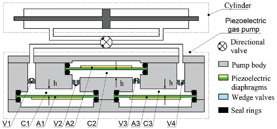
Structure principal diagram of PPLA.
The piezoelectric diaphragms, pump chambers, and wedge valves are referred to as A, C, and V in Figure 1. If an AC voltage with a phase of 0 is provided to A1 and A3, they will vibrate simultaneously. A2 vibrates asynchronously with A1 and A3 when an AC voltage with 180-degree phase is applied to A2. As can be seen in Figure 2(a), A1 and A3 are bent downwards, resulting in a corresponding increase in the volume of C1 and C3; A2 is bent downwards (A2 is positioned in the opposite direction to A1 and A3), resulting in a corresponding reduction in the volume of C2. Because of the difference in pressure between the two sides of the wedge valves, V1/ V3 open and V2 /V4 remain closed. The results in gas entering both C1 and C3. Figure 2(b) shows the operating state of the pump-out. A1 and A3 bend upwards, causing a corresponding decrease in the volume of C1 and C3; A2 bends upwards, causing a corresponding increase in the volume of C2. The pressure difference between the two sides of the vane valve causes V1/V3 to close and V2/V4 to open, resulting in the pumping of gas from C1 into C2. The gas in C3 is pumped out through the outlet. When gas enters the cylinder from the outlet, resulting in an increase in the internal pressure of the cylinder. Once the pressure within the cylinder reaches a sufficient level, it is able to drive the cylinder by overcoming internal friction and external load. A continuous alternating voltage is applied to the piezoelectric diaphragms, resulting in a quantitative and continuous movement of the cylinder to achieve positioning. The output displacement ΔX is completed, as shown in Figure 2(b). When the directional valve is turned, the cylinder piston changes direction and moves backward. Due to its operating frequency being above 90 Hz and the small volume of gas pumped in a single working cycle, the output displacement ΔX of the PPLA is relatively small. With small ΔX in single working cycle and small gas stiffness, PPLA is able to achieve high output accuracy linearity and strong controllability.
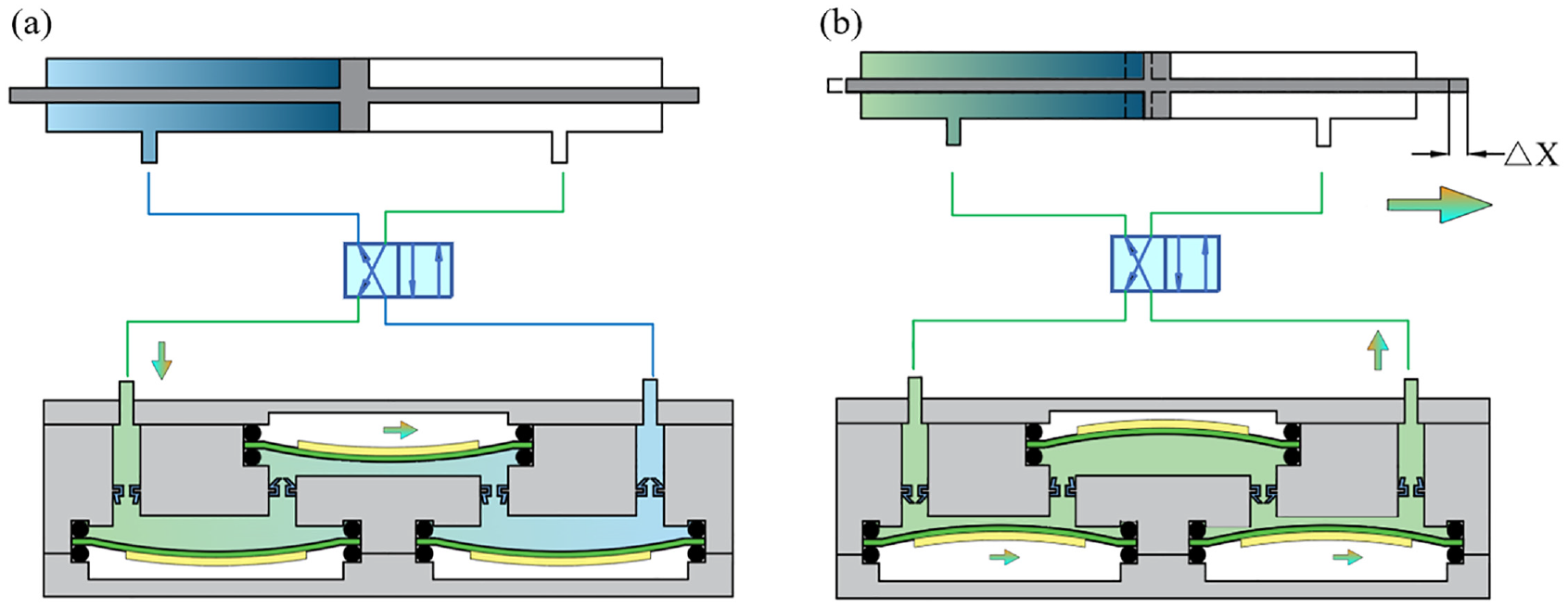
Working process diagram of PPLA: (a) pump-in operation status and (b) pump-out operation status.
The three chambers (C1, C2, C3) are interconnected by four wedge valves (V1, V2, V3, V4). These valves are designed to allow for a unidirectional flow of gas, ensuring proper control and regulation of pressure within the system. As illustrated in Figure 3, the valve wall opens when gas enters via the inlet of the wedge valve and the internal pressure is greater than the outside pressure. The setup allows gas to enter and exit through the valve’s inlet, facilitating controlled gas flow within the system. In contrast, the valve wall shuts to stop the gas from escaping in the opposite direction when the gas flows from the wedge valve’s outlet to the intake, because the external pressure is greater than the internal pressure, as shown in the closed condition in Figure 3. The PPLA’s output performance is able to be enhanced by the wedge valve’s excellent leakage tightness. The high-quality sealing provided by the valve minimizes any unwanted gas leakage, ensuring precise and efficient operation of the system.
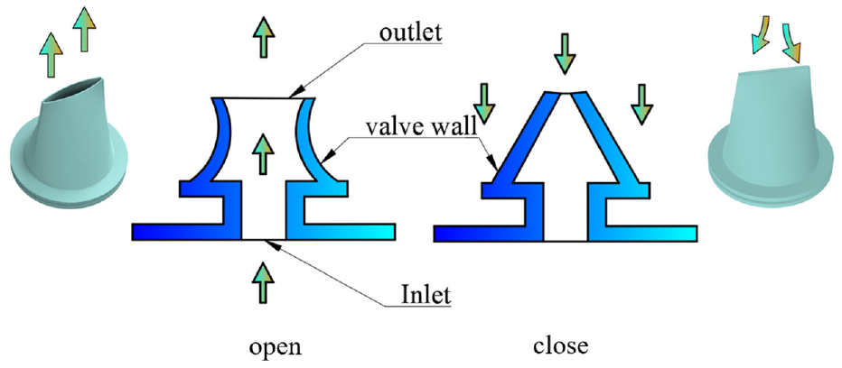
Wedge valve for different working condition.
3. Performance analysis of the PPLA
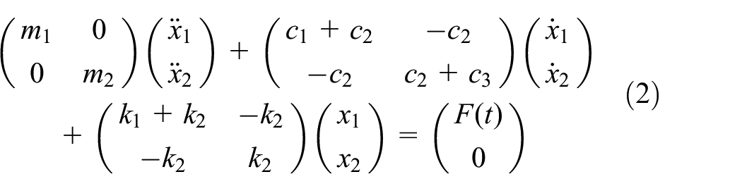
The dynamic model of the PPLA is set up for analysis of the factors which have an influence on the output displacement and output velocity. As shown in Figure 4, the essence of PPLA is to drive the cylinder with a piezoelectric gas pump, where the piezoelectric diaphragm is primarily driven by voltage and further propels the piston with gas as the medium. In the model, m1, c1, and k1 represent the equivalent mass, damping, and stiffness of the piezoelectric diaphragm. k2 and c2 represent the equivalent stiffness and damping of the gas medium. m2 represents the equivalent mass of the piston, which overcomes resistance within the cylinder during motion. Therefore, it is considered that damping has a greater influence on the system and is represented by c3 as the equivalent damping of the piston. x1(t) is the output displacement of the piezoelectric diaphragm, while x2(t) is the output displacement of the piston. The vibration of the piezoelectric diaphragm represents a process in which electrical energy is converted into kinetic energy due to the negative piezoelectric effect. It is able to be expressed as follows:
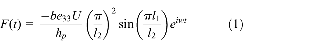
Where b represents the equivalent width of the circular piezoelectric diaphragm, l1 represents the equivalent length of the piezoelectric diaphragm, l2 represents the equivalent length of the metal substrate, and hp represents the thickness of the piezoelectric diaphragm. U is the input voltage, and e33 represents the piezoelectric constant of the piezoelectric material. In the analysis, the circular piezoelectric diaphragm is considered as a kind of beam with fixed supports at both ends. After applying the driving voltage, the vibration equation of the entire system can be represented as follows:
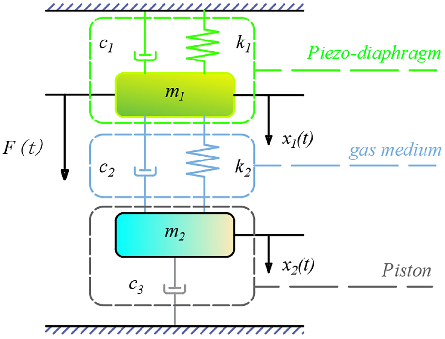
The dynamic model of PPLA.
The system is considered a damped system. Assuming there is a phase difference of
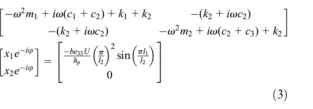
The output of the piezoelectric diaphragm in the entire system can be determined as follows:
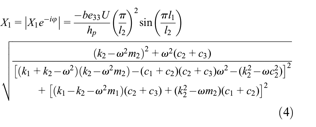
The maximum displacement of the piezoelectric diaphragm is found according to equation (4), which determines the pressure change inside the chamber of the piezoelectric gas pump. The change volume produced by the piezoelectric diaphragm is
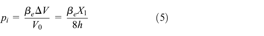
The generated pressure is controlled by h, and it can be observed that they exhibit a negative correlation. When the pressure generated in the pump chamber is high enough, it also affects the displacement of the piezoelectric diaphragm, which in turn weakens the output performance of the gas pump. Throughout, they always satisfy the force balance equation:
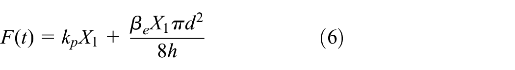
From equation (6), the working displacement of the piezoelectric diaphragm is proportional to the chamber height, but it is not infinitely rising. As depicted in Figure 5, when the operating frequency is set at 5 Hz and voltage at 200 Vpp, it can be observed that the displacement of the piezoelectric diaphragm increases as the chamber height increases. However, it reaches a maximum value when the chamber height reaches 0.5 mm and does not increase further.
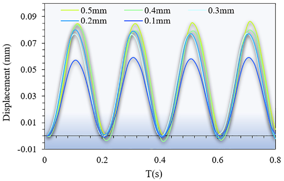
Piezoelectric diaphragm output displacements at different chamber heights, with the origin of the vertical coordinate at the lowest point of the first measurement.
The output flow rate of a single pump chamber can be represented by the following equation:
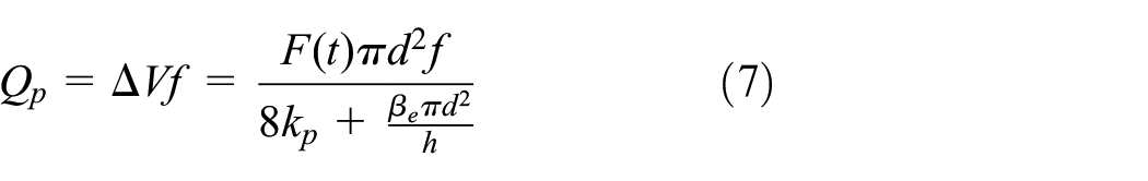
where f is the driving frequency. The range of values of h in equations (5) and (7) needs to be discussed. The heights of the pump chamber need to exceed the maximum displacement of the piezoelectric diaphragm to prevent any collision between them, as the diaphragm deforms inside the chamber. Therefore, the critical minimum value of h is the maximum displacement of the center of the piezo diaphragm, X1. As the value of h increases, the denominator part of equation (10) will eventually approach 8kp rather than zero, and therefore the resulting flow rate Qp cannot increase indefinitely as h increases. Wang et al. (2011) showed that it has a very weak effect on the flow rate when the chamber height exceeds 20X1. The chamber height should not be too high or too low, with a range of values between X1 and 20 X1.
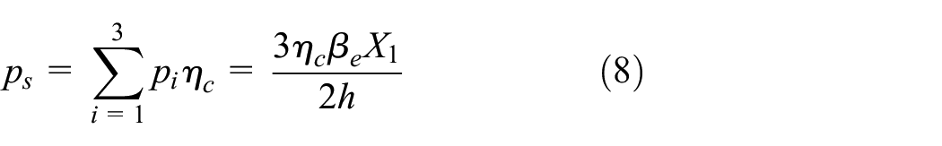
Pi is the output pressure of a single pump chamber. In the overall system, the output pressure of the piezoelectric gas pump is required to be compressed, which then pushes the piston into motion. Generally, the piezoelectric gas pump output pressure is equal to the sum of all chamber outputs. Meanwhile they share the same valve efficiency which is
The gas compression process is carried out quickly (≥90 Hz). The compressed gas does not have enough time to exchange heat with the outside world, so it can be considered that the process is an adiabatic compression process. To meet the process equation of adiabatic compression
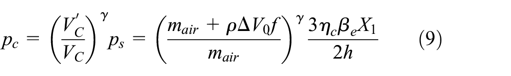
where
where
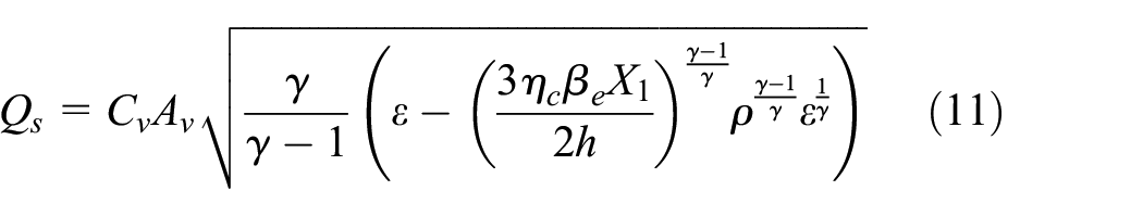
where Cv is the velocity coefficient; Av is the area of the wedge valve orifice;
The output displacement of the PPLA during each working cycle (
According to equation (13), during each working cycle, the output displacement decreases with frequency increases. It means that the step accuracy can be improved by the driving frequency increases. During to the small bulk
4. Experimental setup
The PPLA consists of a piezoelectric gas pump with serial chambers, a directional valve, and a cylinder (SMC: CDJ2B16-20Z-B). Polymethyl methacrylate (PMMA) serves as the material for the piezoelectric gas pump’s body, which is milled and engraved on a CNC machine. The wedge valve utilized in the system is constructed from a rubber material. The piezoelectric diaphragm is flexibly supported by upper and lower sealing rings, enabling increased output displacement at its center. When the chamber height of the piezoelectric gas pump is excessively large, the gas compression efficiency is compromised. Conversely, if the chamber height is too small, it results in increased gas flow resistance. To address these considerations, the chamber height is selected in increments of 0.1 mm, specifically at values of 0.1–0.5 mm. The main parameters are shown in Table 1.
Mian parameters of PPLA.
To explore the output performances, the experimental system shown in Figure 6 is established, through which a series of experiments are performed. During the experiments, a periodic sinusoidal signal driving voltage generated by the wave generator (Agilent, 33522A) is amplified by the power amplifier (Tabor, 9400). The amplified signal is then applied to the PPLA prototype. The motion displacement of the linear slide guide (HIWIN, MGN7C) is measured by the laser displacement sensor (KEYENCE, LK-H080), the amount of collected data is 2000 data points in 0.4 s. It’s mean that 48 cycles of displacement characteristic images are obtained in 120 Hz, which provide sufficient data for data processing. A personal computer is in charge of the collection and processing of the measurement data.
The experimental system of PPLA.
To investigate the impact of the chamber height on the performance of the PPLA, an initial experiment is conducted. The results indicated that the PPLA exhibited subpar performance when the chamber height exceeded 0.5 mm. Therefore, the chamber height is controlled at 0.1–0.5 mm (group G1 to G5). Then the frequency characteristics and voltage characteristics of PPLA without an external load are explored. Next, the performance of PPLA under the external load is explored at the fixed driving voltage and driving frequency.
Ultimately, a cell manipulation platform is constructed, comprising of a drive system and a high-speed photography system. As shown in Figure 7, the drive system consisted of a waveform generator (Agilent, 33522A) and a power amplifier (Tabor, 9400). A microscope (Keyence, model VH-S30) is used for magnification during the experiment, while a high-speed camera (Keyence, model VW-6000E) is used for filming. Zebrafish embryos (700 ± 100 mm in diameter) are fixed with agarose gel V-slots. The zebrafish embryos are manipulated by attaching glass microneedles to the cylinders of the PPLA.
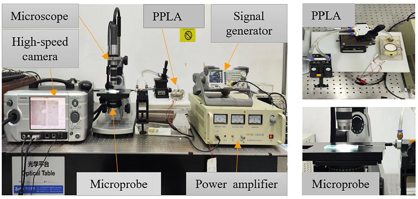
Experimental platform of the cell manipulation system.
5. Experimental results and discussion
5.1. Effects of the chamber height on output performances of PPLA obtained from experiments
Figure 8 presents the frequency characteristics obtained under various chamber heights and a fixed driving voltage of 250 Vpp. As the driving frequency increases, the output velocity of the PPLA also increases. Specifically, when the chamber heights are 0.1, 0.2, 0.3, 0.4, and 0.5 mm, the corresponding maximum output velocities are measured to be 5.83, 8.71, 12.21, 15.14, and 16.62 mm/min, respectively. The result verifies equation (12) for the derivation of performance output, which states that within the appropriate operating range of chamber height, the output velocity of the actuator increases with the h increases. Thus, the output velocity of the PPLA is able to be increased by increasing the chamber height while maintaining a fixed driving voltage. After evaluating the output performance and stability of the PPLA at various chamber heights, it has been determined that the PPLA exhibits favorable performance and stable operation at a driving frequency of 120 Hz. Therefore, the frequency of 120 Hz has been selected for subsequent experiments.
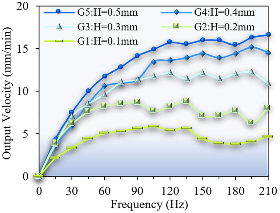
Under the fixed driving voltage of 250 Vpp and different chamber height, the relationship between the frequency and the output velocity. With the increase of the driving frequency, the output velocity increases. The maximum output velocity of 16.62 mm/min is obtained when the chamber heights is 0.5 mm.
Under the different fixed driving frequency and different chambers, the relationship between the output velocity and driving voltage is shown in Figure 9. Within the range of 0–250 Vpp, the output velocity curves of the PPLA exhibit an increasing trend with the rise in driving voltage. At a driving voltage of 250 Vpp, the velocities of G1, G2, G3, G4, and G5 reach their respective maximum values of 5.41, 8.16, 12.16, 13.61, and 15.70 mm/min. The phenomenon indicates that as the driving voltage increases, the driving velocity generated by the piezoelectric diaphragm increases. The larger driving force enhances the output performance of the actuator, satisfying the piezoelectric coupling relationship described in equation (1). The PPLA achieves the best output performance at a chamber height of 0.5 mm (G5). The output velocity of PPLA is increased by increasing the chamber height at a fixed driving frequency.
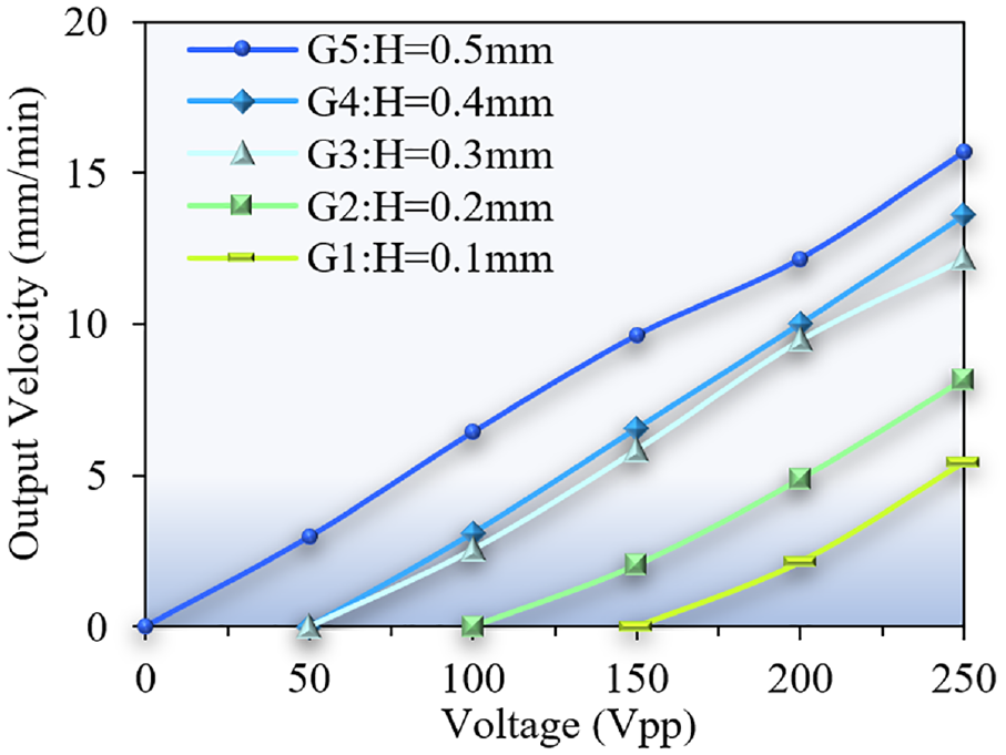
Under the fixed driving frequency of 120 Hz and different chamber height, the relationship between the voltage and the output velocity. The output Velocity profile rises with the increase of the drive voltage. At a drive voltage of 250 Vpp, the drive speed reaches a maximum value of 15.70 mm/min.
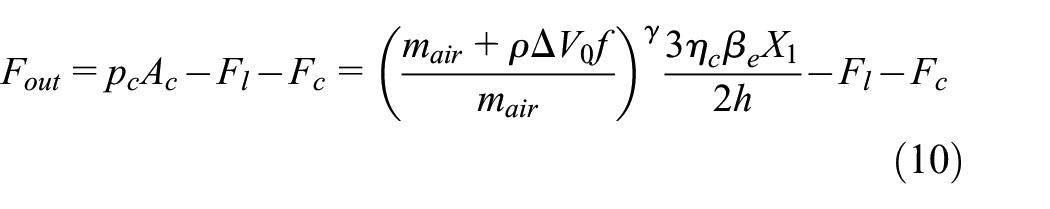
Figure 10 shows the load characteristics of the PPLA at the optimal driving frequency and driving voltage. The output velocity of the PPLA decreases as the load increases. The maximum load supported by the system varies with the chamber height, reaching 4N at a chamber height of 0.1 mm, 7 N at 0.2 mm, and 11 N at 0.3, 0.4, and 0.5 mm, respectively. According to equation (10), as the load increases, it makes the output force of the actuator decrease, further reducing the output velocity. The ability of the PPLA to overcome the load increases as the chamber size gradually increases.
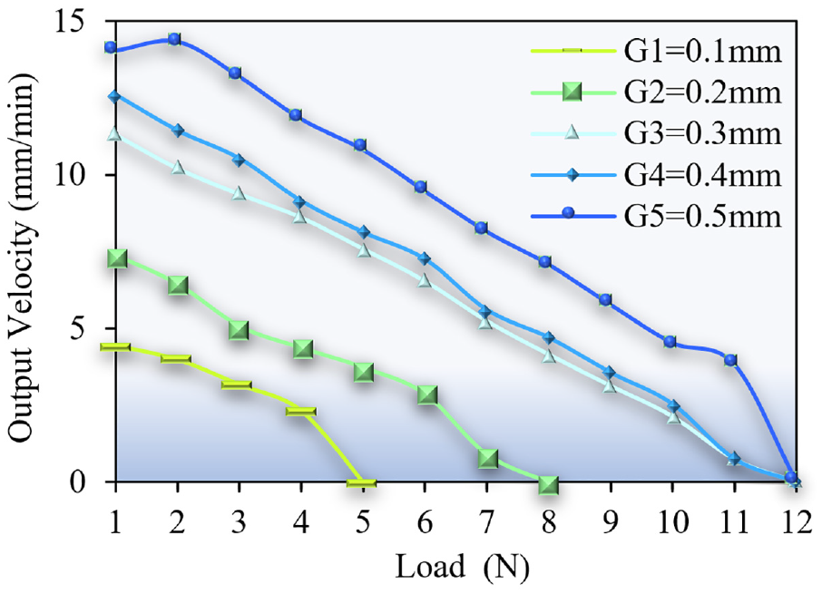
Under 120 Hz and 250 Vpp, the load characteristics of PPLA. The load capacity of the actuator increases as the chamber height increases, with a maximum load capacity of 11 N at a chamber height of 0.5 mm.
5.2. Output displacement performance of PPLA obtained from experiments
Figures 11 and 12 present the displacement characteristics obtained at different driving frequencies and a fixed driving voltage of 250 Vpp. The relationship between the displacement and the time is mathematically fitted by the least-square method. Figure 11 shows that the output displacement of the PPLA exhibits a linear increase with time over a duration of 0.4 s, demonstrating good linearity within the frequency range of 90 to 210 Hz. Figure 12 shows the displacement image of the first 0.04 s in Figure 11, which further validates that the smaller bulk modulus of the gaseous medium brings about high linearity of displacement characteristics, integrating the advantages of pneumatic actuation. The linear correlation coefficients R2 corresponding to the displacement S and time T are measured to be 0.9995, 0.9998, 0.9999, and 0.9996 at the driving frequencies of 120, 150, 180, and 210 Hz, respectively. According to equation (12), as the chamber height increases, the output velocity increases with it. The output velocity tends to stabilize when the driving frequency is greater than 120 Hz. It is worth noting that when the driving frequency increases, it makes the stroke accumulated in the unit operating cycle of the PPLA decrease, which corresponds to equation (13). In other words, the effect caused by the sinusoidal voltage drive signal is reduced, resulting in an increase in the linearity of the actuator. The above results show that the linearity of the displacement output characteristics increases with the increase of the driving frequency, so driving the PPLA at a high frequency (≥90 Hz) produces a smooth displacement output characteristic.
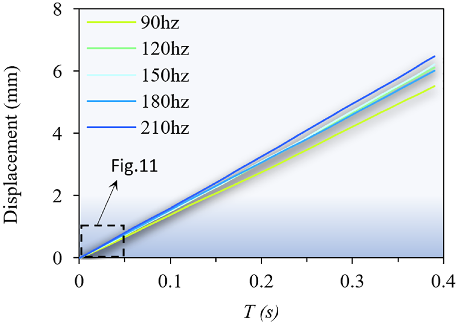
Displacement curves at different driving frequencies in 0.4 s. The PPLA has a smooth output displacement over the 90 to 210 Hz frequency range.
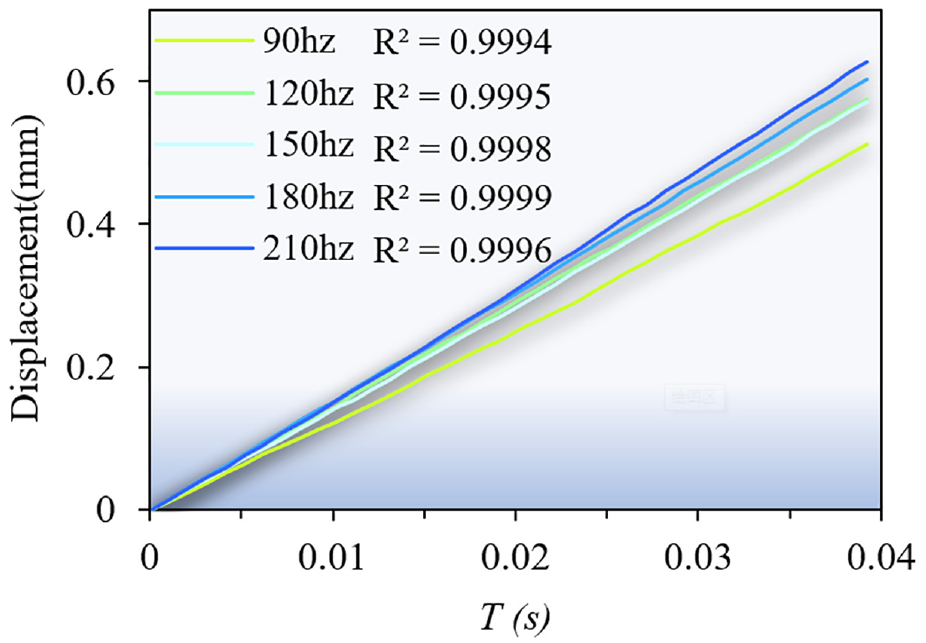
Displacement curves at different driving frequencies in 0.04s. The linear correlation coefficients R2 corresponding to the displacement and time are 0.9995/0.9998/0.9999/0.9996 at the driving frequency of 120/150/180/210 Hz, respectively.
Figures 13 and 14 reveal the displacement characteristics obtained at different driving voltages and fixed driving frequency of 120 Hz. As depicted in Figure 13, the output displacement of the PPLA exhibits a linear increase with time over a duration of 0.4 s. The linearity is observed to be favorable within the voltage range of 50 to 250 Vpp. Figure 14 shows the displacement curve for the first 0.04 s in Figure 13, indicating the high linearity of the displacement characteristics of the PPLA. At the driving voltage of 50 to 250 Vpp, the linear correlation between the output displacement and time is more than 0.9994. The above result shows that the displacement of PPLA keep an excellent linearity at the driving voltage of 50–250 Vpp.
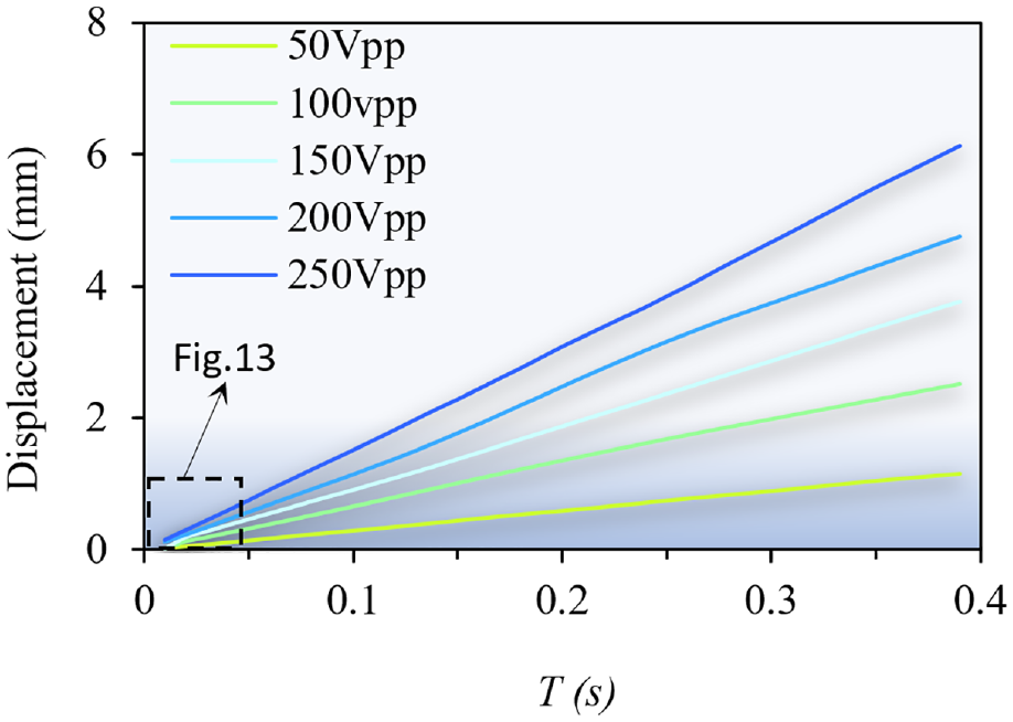
Displacement curves at different driving voltages in 0.4 s. The PPLA has a smooth output displacement over the 50 to 250 Vpp.
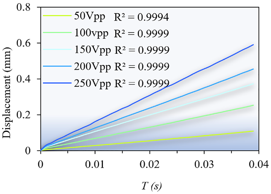
Displacement curves at different driving voltages in 0.04 s. At the driving voltage of 50 to 250 Vpp, the linear correlation between the output displacement and time is more than 0.9994.
The impact of an external load on the output performance is investigated at 250 Vpp and 120 Hz. The results are displayed in Figures 15 and 16, external loads ranging from 1 N to a maximum of 11 N. Figure 15 displays the displacement characteristic of the system under external loads of 2, 5, 8, and 11 N over a duration of 0.4 s. The output velocity decreases with the external load increases. The PPLA is still working at higher loads and maintains a smooth output displacement characteristic. Figure 16 illustrates the linearity of the fitted line during the first 0.04 s of Figure 15 under external loads of 2, 5, 8, and 11 N. The corresponding linear correlation coefficients are measured to be 0.9963, 0.9999, 0.9999, and 0.9999, respectively. The results prove that PPLA still work smoothly under different loads. The experimental results are in accordance with the derivation of equation (13), the higher the load, the smaller the displacement per unit output, which implies an increase in the linearity of the actuator.
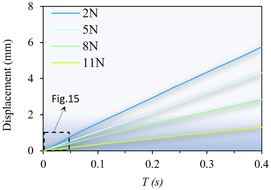
Displacement characteristic under different external load in 0.4 s. The PPLA is still working at higher loads and maintains a smooth output displacement characteristic.
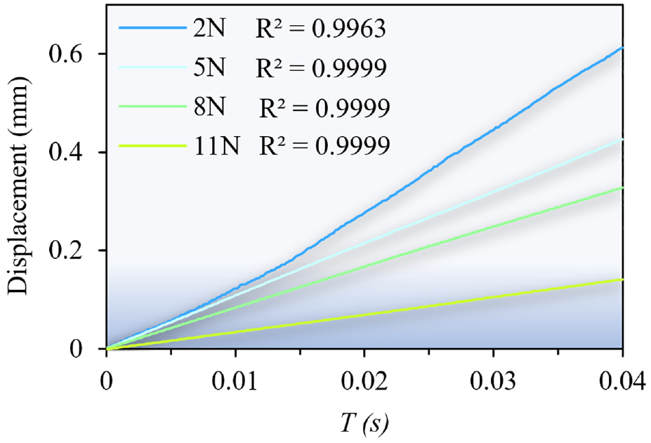
Displacement characteristic under different external load in 0.04 s. The linearity of the fitted line at the first 0.04 s in Figure 15, which are 0.9963/0.9999/0.9999/0.9999, under external loads of 2N/5N/8N/11N, respectively.
5.3. Experiment of cell manipulation
To prove the positioning accuracy of PPLA, the boundary of the zebrafish embryo is used as the positioning point. The tip of the driven glass microprobe is brought closer to the localization point and stopped at the localization point. Then, the directional valve shifts the glass microprobe’s motion in the opposite direction, pushing the microprobe away from the zebrafish embryo. To verify the accuracy of the PPLA, multiple repetitions of the experiment are performed. In the experiment, a sinusoidal signal with a group of 30 pulses serves as the driving voltage signal. Moreover, it is employed to carry out the repeated placement and realize the quantitative movement of the glass microprobe. The localization findings are shown in Figure 17(a) to (e), where the first to fifth glass microprobes that stopped at the positioning location are recorded. The outcomes show that PPLA has a high level of positioning accuracy.
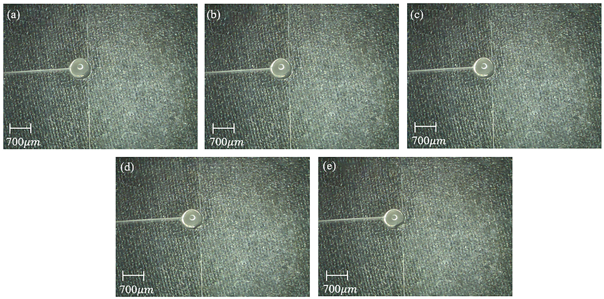
Repeated localization experiments of PPLA with cell wall as localization point. The actual working situation is shown in the Supplemental Video 1: (a) first positioning, (b) second positioning, (c) third positioning, (d) fourth positioning, and (e) fifth positioning.
The potential of zebrafish embryos for applications involving cell manipulation must be confirmed. One of the typical uses of cell manipulation is microinjection, and the practical viability of PPLA is demonstrated by imitating drug injection into zebrafish embryos. Figure 18(a) displays the stable forward movement of the tip of the glass microprobe, while Figure 18(b) demonstrates the successful entry of the microprobe into the zebrafish embryo. Additionally, Figure 18(c) illustrates how the directional valve alters the direction of movement of the PPLA. The microprobe is pushed backward and withdrawn from the zebrafish embryo. The results of the experiments demonstrate that the suggested actuator is able to replicate the manipulation of zebrafish embryos with success and has the potential to be used for cell manipulation and other micromanipulations.
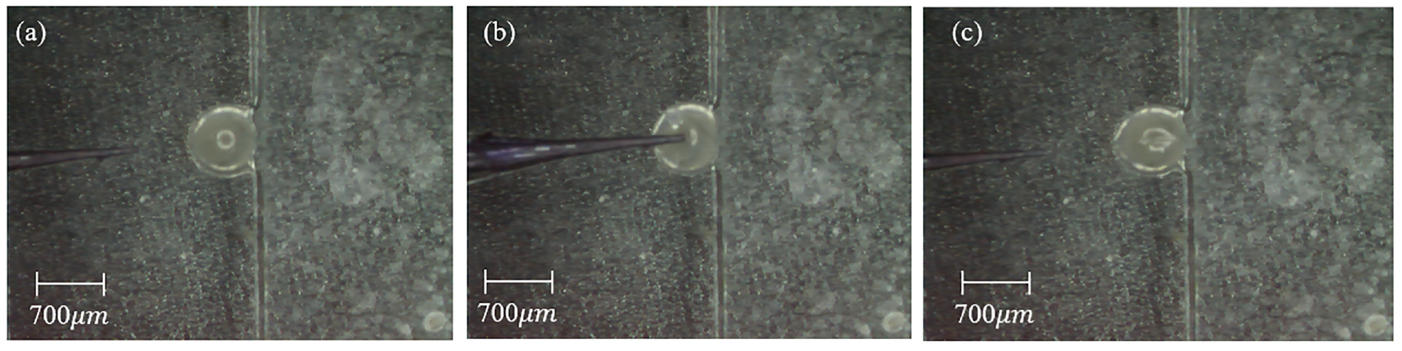
Injection processes of the zebrafish embryo: (a) approaching process, (b) penetration process, and (c) retraction process. The actual working situation is shown in the Supplemental Video 2.
6. Conclusion
The proposed piezoelectric pneumatic linear actuator (PPLA) combines the comprehensive advantages of piezoelectric actuators and pneumatic drive. It introduces a novel approach to the field of cell manipulation. A prototype of the PPLA has been successfully fabricated. Theoretical analysis and experiments provide evidence of the feasibility of the PPLA in the field of cell manipulation. The experimental results demonstrate that:
(1) The PPLA, which combines piezoelectric and pneumatic drives, is a viable option. The optimal output velocity of PPLA is 16.62 mm/min.
(2) The output velocity exhibits a positive correlation with the chamber height. Specifically, When the chamber height is 0.1 mm, the maximum output velocity is 5.83 mm/s. With the chamber height increases to 0.5 mm, the maximum output velocity increases to 16.62 mm/s. As the operating displacement of the piezoelectric diaphragm is positively correlated with the chamber height. However, when the chamber height reaches 0.5 mm, the output displacement of the piezoelectric diaphragm is not able to continue to rise due to the excessive pressure inside the chamber, limiting the output performance of the actuator.
(3) The PPLA achieves excellent linearity in positioning, with the displacement exhibiting a linearity higher than 0.999 at the optimal chamber height of 0.5 mm. and under the load of 1–11 N, the linearity is still greater than 0.999. Since the fluid medium used is air, the value of the gas bulk modulus is very small, which means that the increment of the gas pressure during compression is smooth, enabling high linearity of the actuator to be achieved.
(4) The PPLA exhibits potential for application in the field of cell manipulation. It effectively drives the microprobe toward the surface of the zebrafish embryo, enabling successful cell injection.
Overall, this work provides a novel approach for manipulating biological cells. Building upon this, it opens up new possibilities for driving technologies in the fields of healthcare, biochemistry, aerospace, precision machinery, and electronic information. The insights gained from this work will hold significant value for the design and optimization of piezoelectric hydraulic actuators in engineering practice. Future efforts will focus on further enhancing the high linearity positioning of PLAA, as well as advancing miniaturization and precision, thus expanding the application domains of such actuators.
Footnotes
CRediT authorship contribution statemen
Song Chen: Conceptualization, Investigation, Methodology, Writing—review and editing, Resources, Supervision. Zijian Huang: Conceptualization, Software, Investigation, Writing—original draft, review, and editing, Validation, Visualization. Wentao Cheng: Conceptualization, Formal Analysis, review. Xuan Fang: Conceptualization, Formal Analysis. Yilei Xie: Conceptualization, Formal Analysis. Zhonghua Zhang: Conceptualization, Methodology. Jiantao Wang: Conceptualization, Formal Analysis, Resources. Junwu Kan: Project Administration, Conceptualization, Formal Analysis.
Declaration of conflicting interests
The authors declared no potential conflicts of interest with respect to the research, authorship, and/or publication of this article.
Funding
The authors disclosed receipt of the following financial support for the research, authorship, and/or publication of this article: This work was supported by the National Natural Science Foundation of China [grant numbers 51805489]; Hebei Natural Science Foundation [grant numbers No. E2020203070]; Zhejiang Natural Science Foundation Project [grant numbers No.LY24E050006].
Data availability statement
Data will be made available on request.
Supplemental material
Supplemental material for this article is available online.
References
Supplementary Material
Please find the following supplemental material available below.
For Open Access articles published under a Creative Commons License, all supplemental material carries the same license as the article it is associated with.
For non-Open Access articles published, all supplemental material carries a non-exclusive license, and permission requests for re-use of supplemental material or any part of supplemental material shall be sent directly to the copyright owner as specified in the copyright notice associated with the article.