
Abstract
During the morphing of flexible skins, local strain concentration may occur in the face-sheet due to different bonding methods between the face-sheet and the skeleton. To overcome this problem, we propose a strategy to improve the uniformity of the strain distribution through rationally distributing the connection areas between the face-sheet and skeleton of the sandwich-flexible-skin, and develop a topology optimization method for determining the optimal distribution of the connection areas. In this method, the connection areas between the face-sheet and the support skeleton are considered as the virtual adhesion layer comprising of adhesion materials. Based on the topology optimization idea, the distribution of connection areas is described by allocating the presence and absence of the adhesion material. The optimization model is established with minimizing the globe stress of the face-sheet as the objective function, the volume fraction of the design domain as the constraint. The effectiveness of the proposed method is verified through examples involving tensile and rotational states of the sandwich-flexible-skin with Ω-shaped honeycomb structure, and the results show that the optimization method can significantly improve the strain distribution of the face-sheet. Finally, a variable-sweep structure for unmanned aerial vehicles (UAVs) is designed to explore the practical value of the proposed method.
Keywords
1. Introduction
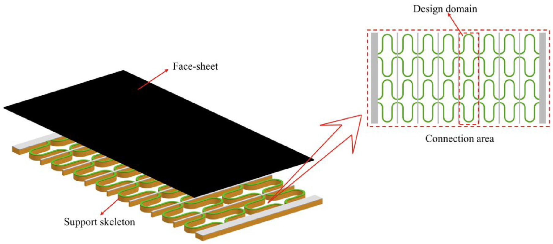
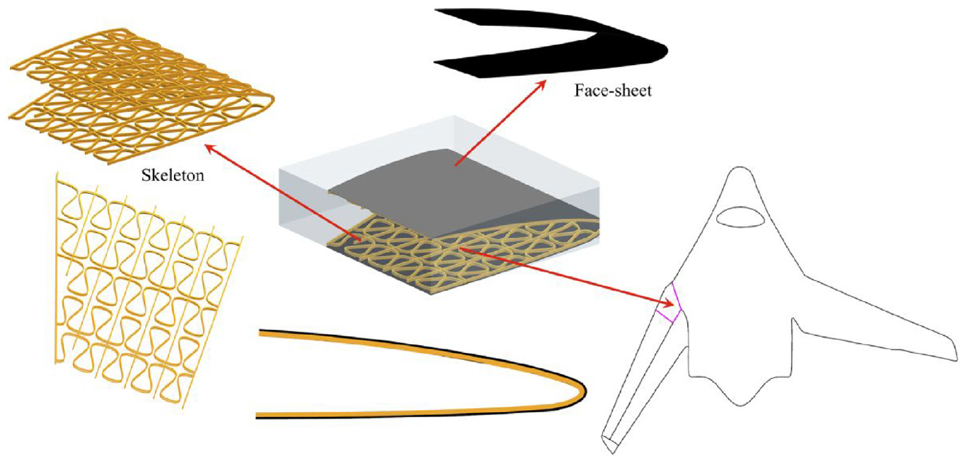
Flexible skins have completely changed the morphing limitation of traditional rigid skins and played a crucial role in the field such as morphing wings. The specialized working environments demand that flexible skins possess not only the ability to maintain continuous and smooth in-plane morphing but also sufficient out-of-plane stiffness to withstand aerodynamic loads. One kind of flexible skin relies on the inherent elasticity of materials to achieve morphing, as represented by materials such as silicone rubber (Bubert et al., 2010; Chen et al., 2013) or shape memory polymers (Han et al., 2016; Leng et al., 2011); another kind utilizes the movement of rigid structures to achieve morphing, such as fish-scale-based overlapping skins (Long JR et al., 1996), sliding skins with segmented rigid panels (Yu et al., 2018), and fishbone-like structures (Woods and Friswell, 2012), and yet another kind achieves morphing through the cumulative effect of periodic structures, such as corrugated structures (Dayyani et al., 2015; Previtali et al., 2015; Yokozeki et al., 2006) and honeycomb structures (Chang and Shen, 2018; Farrokhabadi et al., 2022; Liu et al., 2018b; Olympio and Gandhi, 2010b; Qi et al., 2021). Among the numerous design schemes, the sandwich-flexible-skin, a kind of composite flexible skins, which is composed of face-sheets and sandwiched honeycomb cores, stands out as highly promising for practical applications. There are many researches on this kind of flexible skins, including cores sandwiched with the traditional hexagonal honeycomb (Olympio and Gandhi, 2010a), the accordion honeycomb (Olympio and Gandhi, 2010b), and the zero Poisson’s ratio honeycomb (Bubert et al., 2010), the re-entrant honeycomb (Heo et al., 2013), and other cellular structures. Additionally, some studies have employed optimization techniques to obtain innovative designs (Ai et al., 2018; Chang and Shen, 2018). In Figure 1, these structures all utilize a honeycomb core as the support skeleton, and are covered with a low modulus, high-strain face-sheet. The face-sheets maintain a smooth aerodynamic surface, while the honeycomb cores provide a certain out-of-plane stiffness to withstand aerodynamic loads. Common modes of in-plane morphing for flexible skins include tension, shear, rotation, as shown in Figure 2.
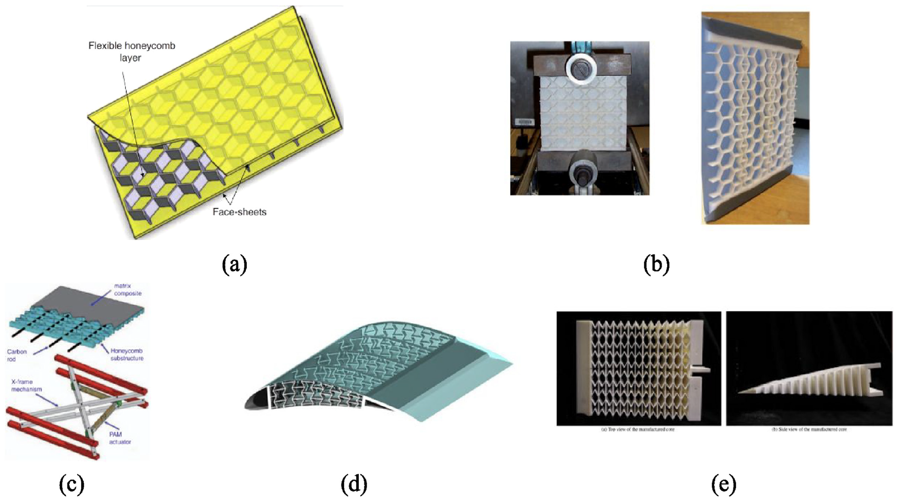
Composite flexible skins: (a) hexagonal honeycomb (Olympio and Gandhi, 2010a), (b) hybrid and accordion honeycomb (Olympio and Gandhi, 2010b), (c) zero Poisson’s ratio honeycomb and corresponding actuator (Bubert et al., 2010), (d) re-entrant honeycomb (Heo et al., 2013), (e) optimized honeycomb (Ai et al., 2018).
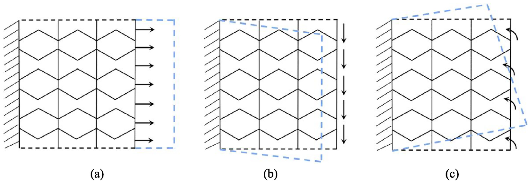
Several in-plane morphing modes: (a) tension, (b) shear, (c) rotation.
When the face-sheet is fully connected to the honeycomb structure, the local strain concentration in the face-sheet may occur during morphing. Excessive local tensile stress increases the risk of face-sheet failure, while excessive local compressive stress can cause wrinkles in the face-sheet. Therefore, the magnitude of the local stress needs to be reduced. The morphing performance of the face-sheet is affected directly by the distribution of connection areas (distribution of connection areas in which the face-sheet surface and the skeleton are bonded through adhesion), and a reasonable distribution of connection areas can relieve face-sheet strain concentration.
Some works on the issue of the face-sheet strain distribution have been conducted. Murray et al. studied the FMC (flexible matrix composite) composed of high-strain-capacity matrix materials and high-modulus fiber materials for one-dimensional deformable wings. The matrix dominant direction corresponded to the deformation direction, while the fiber dominant direction was perpendicular to the deformation direction. By orthogonally distributing these two materials with significant differences in modulus, the flexible skin had both high strain capacity and the ability to bear out-of-plane loads during deformation (Murray et al., 2010). Olympio et al. focused on flexible skins consisting of a cellular substructure and pretensioned face-sheets for shear morphing applications. The unit cell of the substructure was a strand with some strain-relief features to reduce the peak strains. The study suggested that curved strands (Gaussian- or Cosine-shaped strands) can better reduce the peak strains and the morphing actuation work (Olympio et al., 2010). You et al. designed a new gripper pin structure for morphing wings that can decouple in-plane stiffness from out-of-plane stiffness. Finite element analysis for variable camber wing showed that the stress of the gripper pin skin was much lower than those of the skin made of bulk materials (You et al., 2019). Liu et al. investigated the effect of varying temperature conditions on the pressure fluctuation of the flexible inflatable wing and discussed how the strain of the wing skin film changes along the span and chord-wise characteristic lines (Liu et al., 2018a). Optimizing the fiber orientation and volume fraction of fiber-reinforced composite structures (CFRCSs) to reduce stress concentration and improve the structural ultimate strength offered a design approach for flexible skins (Hou et al., 2021; Shafighfard et al., 2019; Zhang et al., 2018). The presence of reinforcing fibers enhances the out-of-plane bending stiffness of the composite structure, but it also increases the in-plane stiffness, which limits the structural morphing capacity to some extent. The challenge of balancing the out-of-plane bearing capacity and in-plane morphing ability of the flexible skin to accommodate large-scale morphing still remains (Murugan et al., 2012; Murugan and Friswell, 2013). In addition, a new design concept for morphing skins that combines three key design principles was proposed (Woods and Heeb, 2023). The three design principles were: the use of thermoplastic elastomers that can be 3D printed into complex geometries; the use of multiple nozzle 3D printers to combine different stiffnesses of materials into a single component; and leveraging geometrical anisotropy and structural scaling laws to help decouple morphing skin design constraints. The skin structure could achieve significant morphing with low energy consumption and strong resistance to aerodynamic loading by the combination of the three design principles. But the above researches do not sufficiently explore the influence of the bonding method by which the face-sheet is attached to the skeleton on the performance of the face-sheet.
The strain distribution of the face-sheet is directly related to the connection distribution between the face-sheet and the support skeleton. It is an effective way to improve the face-sheet strain distribution by designing the distribution of connection areas reasonably. In this paper, we propose a topology optimization-based method for designing the distribution of the connection areas in flexible skins. In this method, the contact surface between the face-sheet and the support skeleton is taken as the virtual adhesion layer comprising of adhesion materials, through rationally allocating the presence or absence of the adhesion material to design the connection layout. Based on the topology optimization idea, the distribution of connection areas is described by determining which areas in the adhesion layer should assign material. The optimization model is established with minimizing the globe stress of the face-sheet as the objective function, the volume fraction of the design domain as the constraint.
The remaining sections of this paper are organized as follows. Section 2 establishes the topology optimization model for alleviating the strain concentration. Section 3 introduces three examples to validate the effectiveness of the proposed method. Finally, the conclusions are provided in Section 4.
2. The optimization method for improving strain distribution
2.1. Problem statement
The combination of rubber-based composites as the face-sheet and honeycomb cores as the internal support has become a favored choice for flexible skins. A classic configuration based on the U-shaped honeycomb core (Wang et al., 2022) is illustrated in Figure 3. The face-sheet is adhered to the surface of the honeycomb skeleton.
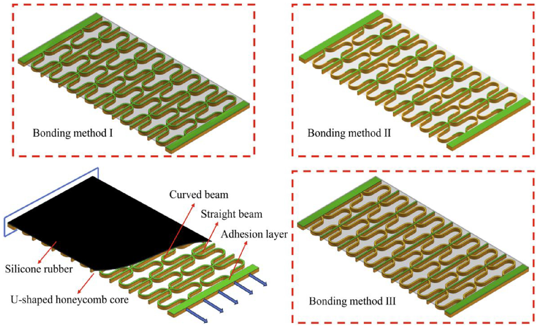
Different bonding methods between the face-sheet and skeleton.
This work considers three different potential methods for bonding the face-sheet to the core. In bonding method I, both the straight beams and curved beams of the honeycomb core are bonded to the face-sheet. Bonding method III only involves bonding the straight beams, leaving the curved beams unbonded. Bonding method II is in between the two, where the curved beams are only partially bonded.
Local strain concentration can be caused by the different bonding methods. Taking the span morphing as an example, one end of the flexible skin is full fixed and the other end is stretched for a certain distance to produce in-plane morphing. Analysis results for different bonding methods are obtained in Figure 4. The maximum strain of the face-sheet in bonding method I is higher than that of the other two bonding methods. In contrast, in bonding method III, the strain of the face-sheet is the smallest and uniform. Proper reduction of the connection area between the face-sheet and the skeleton can reduce the magnitude of strain and improve strain distribution.
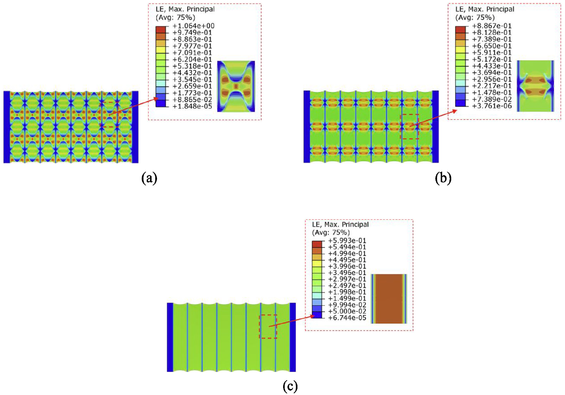
The analysis results under different bonding methods: (a) bonding method I, (b) bonding method II, (c) bonding method III.
It is evident that different bonding methods have a significant effect on the performance of the face-sheet. Therefore, we introduce topology optimization techniques (Sigmund and Maute, 2013; Sigmund, 2001) to optimize the distribution of the adhesion layer to find good bonding methods between the face-sheet and the skeleton core in this paper.
2.2. The topology optimization model
The general configuration of the sandwich-flexible-skin is divided into three parts: the face-sheet, connection area, and support skeleton, as shown in Figure 5. The connection area, is considered a thin layer sliced from the surface of the support skeleton, part of which functions as the design domain. Since the magnitude of strain is positively correlated with the stress level, the conventional p-norm global stress measure is adopted for an approximation of the maximum stress (Fan et al., 2019; Xia et al., 2018), which reduces the face-sheet strain level by reducing the stress. The element densities of the design domain are employed as the design variables, ranging from 0 to 1, in which “0” represents void material, indicating that the face-sheet and skeleton are separate, and “1” represents solid material, indicating that the face-sheet and skeleton are bonded together. The densities of intermediate elements introduce a penalty term to ensure black-and-white solutions. The optimization formulation for the minimization of the global stress subject to a material usage constraint is described as follows:
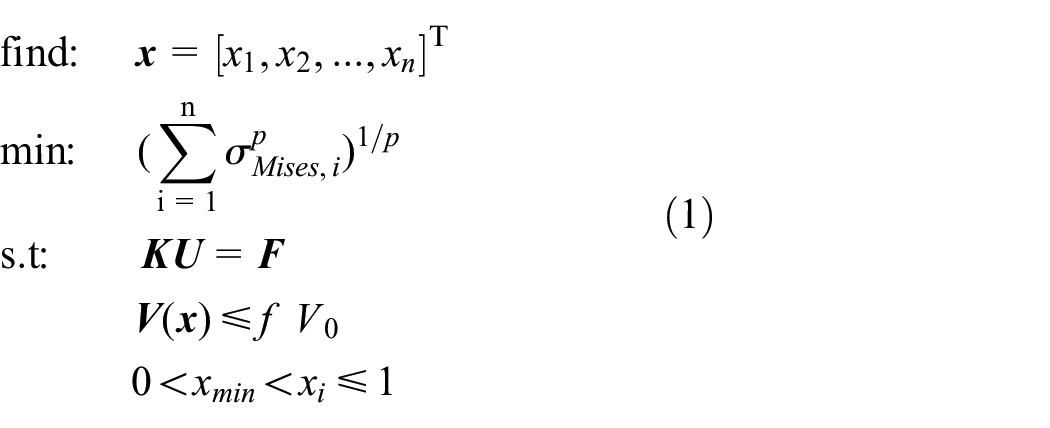
where

where,
The optimization model of sandwich-flexible-skin.
3. Numerical examples
A novel Ω-shaped honeycomb structure is utilized to demonstrate the proposed method. Drawing on design experience from relevant literature (Ahmad and Ajaj, 2022; Chang et al., 2020; Hajarian et al., 2022), the thickness of the silicone rubber face-sheet is set to 0.4 mm, and the thickness of the support skeleton is set to 10 mm. The flexible skin is shown in Figure 6. The support skeleton has sufficient stiffness to reduce the bending effects caused by out-of-plane loads. Due to the symmetry and periodicity of the honeycomb structure, a Ω-shaped unit cell is chosen as the subject of study. The Ω-shaped unit cell consists of three parts: face-sheet, connection area, and support skeleton. The connection area is a thin slice structure that is cut from the curved part of the support skeleton. The inner surface of the face-sheet is firmly adhered to the skeleton’s straight beams, while the connection area acts as a thin adhesion layer. The thickness of the connection area is set to 0.2 mm.
The flexible skin based on Ω-shaped unit cells.
Three examples are conducted to validate the effectiveness of the proposed method. These examples include the optimization scenarios of Ω-shaped unit cells under tensile and rotational states. Additionally, a scaled-down structure for variable-sweep wings of UAVs is designed to further demonstrate the practical value of the optimization method.
3.1. The optimization design of the connection area under the tensile state
Initially, the face-sheet and skeleton are completely bonded together. Given the significant modulus difference between the two materials, shared nodes are employed between the face-sheet and skeleton meshes. The irregular Ω-shaped curve presents a challenge in dividing the face-sheet structure into hexahedral meshes. Hence, a combination of C3D8RH (hexahedron linear solid elements composed of eight nodes with reduced integration and hybrid formulation) and C3D6H elements is used to mesh the face-sheet, while C3D8R elements are used to divide the skeleton. The global mesh size is 0.2 mm. Silicone rubber is considered to be an isotropic material with a completely incompressible volume. The parameters of the Mooney-Rivlin model are
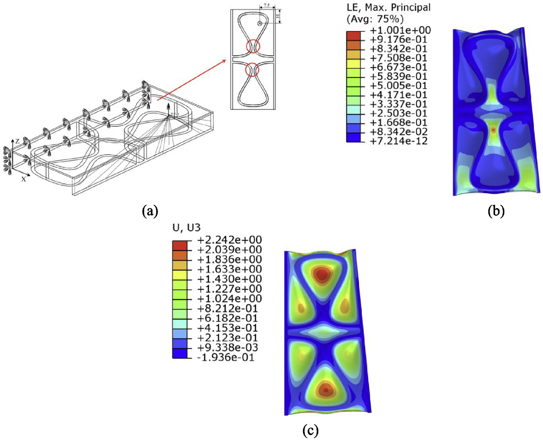
One end of the unit cell is fixed, and the other end is stretched by 2.2 mm to simulate the tensile state. Taking the peak pressure on the wing of a certain UAV model at its maximum flight speed as a reference, and using a low-fidelity way to assess the maximum out-of-plane displacement of the face-sheet, so a uniform pressure of 0.04 MPa is applied to the inner surface of the face-sheet. The boundary conditions, strain and out-of-plane displacement of the face-sheet are illustrated in Figure 7. Owing to the narrow gaps of the Ω-shaped skeleton, as shown in the red circle in Figure 7(a), the face-sheet bonded near the narrow gaps of the skeleton appears local excessive strain and concentrated strain distribution when subjected to a small displacement drive.

The boundary conditions, strain and out-of-plane displacement of the face-sheet under the bonding method I: (a) boundary conditions, (b) strain, (c) out-of-plane displacement.
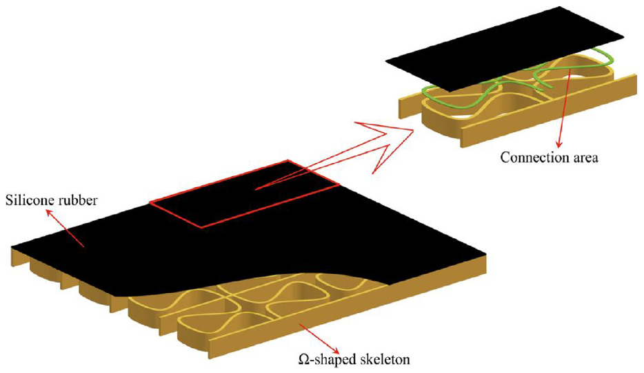
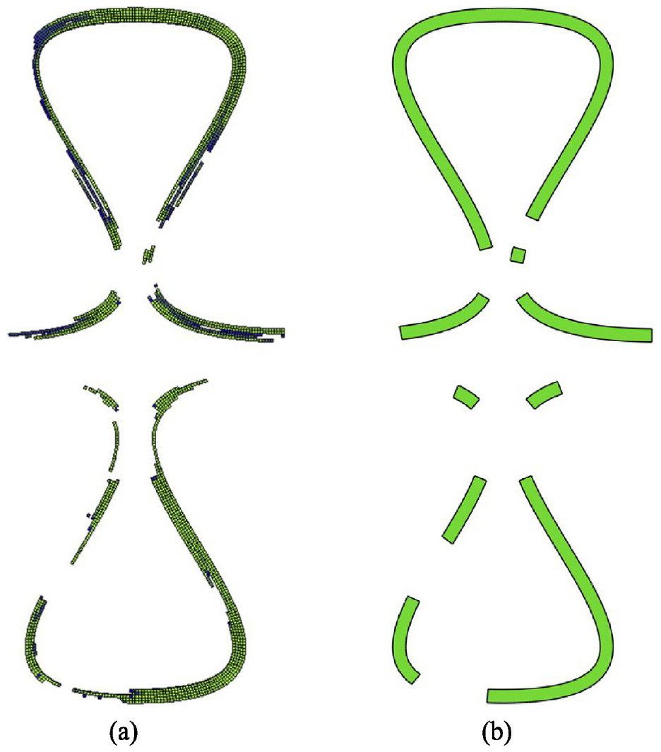
To address the issue of strain concentration in the face-sheet, the optimization of connection areas is performed with a volume fraction
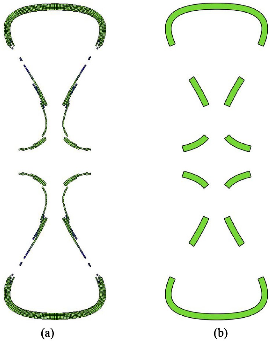
The optimization results under the tensile state: (a) initial result, (b) simplified result.
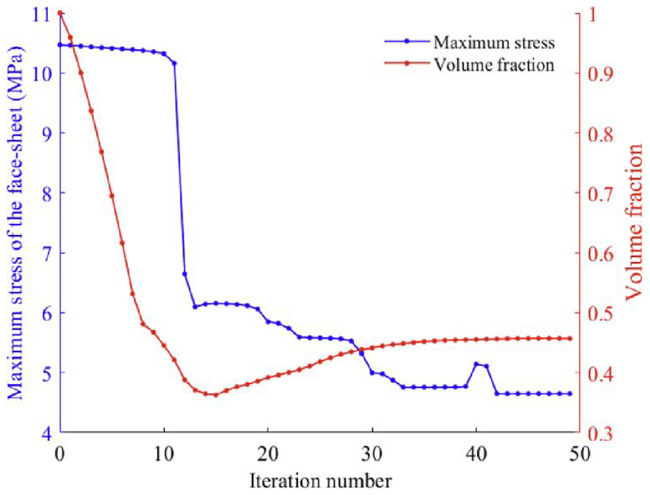
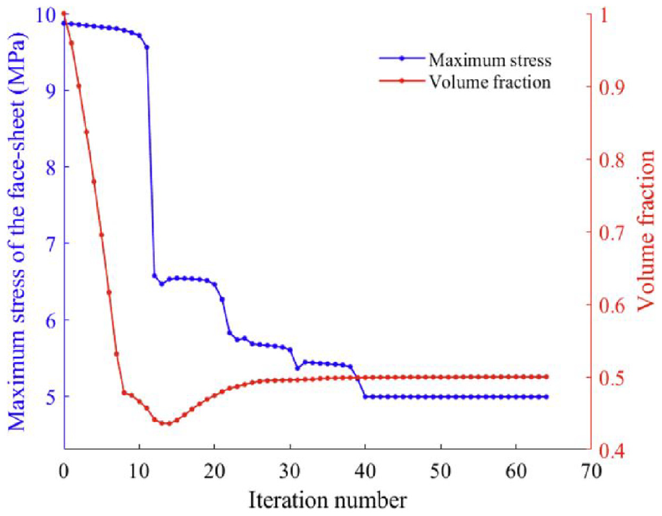
Convergence curve under the tensile state.
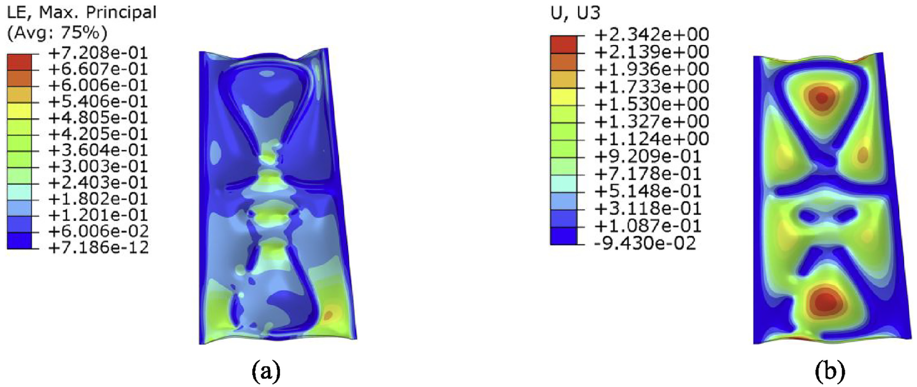
The optimized result in Figure 8(b) is imported into Abaqus for subsequent recalculation. The strain distribution and the out-of-plane displacement of the face-sheet are shown in Figure 10.
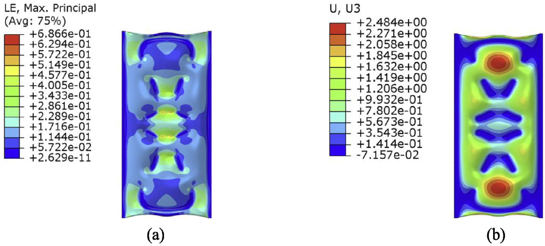
The strain and out-of-plane displacement under the bonding method II: (a) strain, (b) out-of-plane displacement.
A conspicuous observation is that the maximum strain decreases significantly from 102.9% to 68.7%, a reduction of about 33.2%. The strain distribution of the face-sheet before optimization is concentrated in the narrow gaps of the curved configuration, while the strain distribution after optimization is more scattered and the strain areas are significantly reduced.
Likewise, the strain and out-of-plane displacement results of the face-sheet under bonding method III are shown in Figure 11. It can be seen from Figure 11(a) that the strain in most areas of the face-sheet does not exceed 60%. Because the face-sheet is not bonded to the curved beam, it experiences excessive out-of-plane displacement under pressure, which pulls the face-sheet which bonded to the straight beam and increases the strain values.
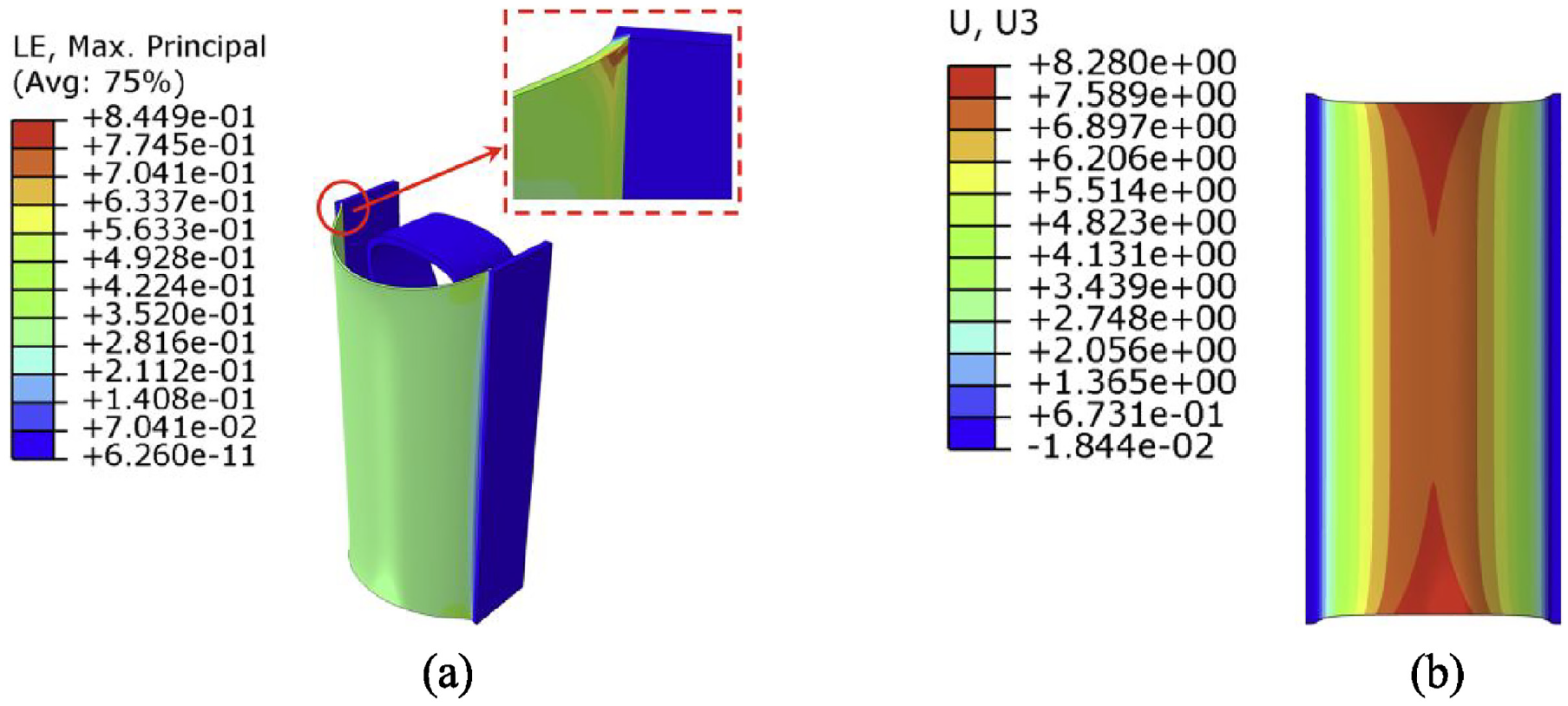
The strain and out-of-plane displacement under the bonding method III: (a) strain, (b) out-of-plane displacement.
To more clearly compare the three bonding methods, the maximum strain of the face-sheet, the maximum out-of-plane displacement, and the actuation force of the unit cell are summarized in Table 1. Among the three bonding methods, bonding method II has the lowest maximum strain, indicating that optimizing the connection layout between the face-sheet and the skeleton can effectively reduce the magnitude of maximum strain. Honeycomb structures cannot be manufactured as complete solid structures, and there is always a suspended area between them. Under the negative pressure load, the larger the suspended area, the more pronounced the out-of-plane displacement. Excessive out-of-plane displacement will damage the smoothness of the face-sheet. The maximum out-of-plane displacement of the bonding method II is very close to the result of the bonding method I. The reduction of the connection area in bonding method II has no significant negative impact on the smoothness. In contrast, bonding method III has the largest out-of-plane displacement, approximately 3–4 times that of the other two bonding methods. This bonding method undoubtedly severely damages the smoothness of the face-sheet.
The maximum strain, maximum out-of-plane displacement, and actuation force under the tensile state.
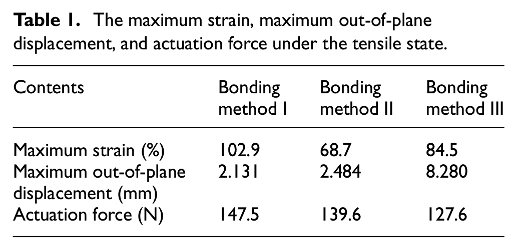
In the future design of morphing skins, more careful attention to minimizing the amount of adhesive used to bond the face-sheet and substructure would likely reduce the in-plane stiffness of the morphing skin significantly (Bubert et al., 2010). The smaller the connection area between the face-sheet and the skeleton, the smaller actuation force required by the unit cell. Compared to the bonding method I, the actuation force of the bonding method II and the bonding method III has decreased to some extent. The reduction proportion of actuation force depends on the impact of the adhesive and the substructure for the overall flexible skin stiffness. Through a comprehensive comparison, each of the three bonding methods performs best in one of the three evaluation criteria. Here, the strain value of the face-sheet is given the highest priority, followed by out-of-plane displacement, with the actuation force being the lowest priority. Therefore, bonding method II is determined to be the best choice among the three.
3.2. The optimization design of the connection area under the rotational state
In the rotational state, one side of the structure is fixed, and the other side is rotated by 0.1 radians in the rotation point plane. Similarly, a pressure of 0.04 MPa is applied to the inner surface of the face-sheet. The boundary conditions, strain and out-of-plane displacement are illustrated in Figure 12.
The boundary conditions, strain and out-of-plane displacement of the face-sheet under the bonding method I: (a) boundary conditions, (b) strain, (c) out-of-plane displacement.
Due to the different loading conditions, the optimized result loses symmetry (Figure 13). Nevertheless, notable similarities in optimization details are still present, particularly in the lower portion of the Ω-shaped design domain, where the narrow gaps are also optimized without any surprises. Convergence curves illustrated in Figure 14 show a clear convergence of the optimization process. Eventually, the volume fraction converges to the desired values.
The optimization results of the rotational state: (a) initial result, (b) simplified result.
Convergence curves under the rotational state.
The well-organized optimized configuration is reimported into the unit cell for further analysis, and the results are showed in Figure 15. It is found that the maximum strain decreases by approximately 28% compared with Figure 12(b). Moreover, the high strain regions are no longer concentrated in the narrow gaps of the curved configuration, avoiding the hazardous areas.
The strain and out-of-plane displacement under the bonding method II: (a) strain, (b) out-of-plane displacement.
The strain and out-of-plane displacement results of the face-sheet under bonding method III are shown in Figure 16. Although the majority of the face-sheet is in a state of low strain, due to the influence of the bonding method, the strain values at the connection between the straight beam and the face-sheet increase, and the out-of-plane displacement of the whole face-sheet is too large.
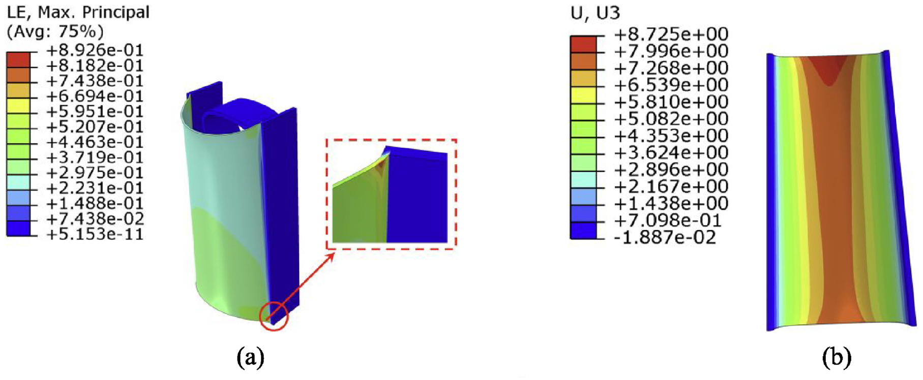
The strain and out-of-plane displacement under the bonding method III: (a) strain, (b) out-of-plane displacement.
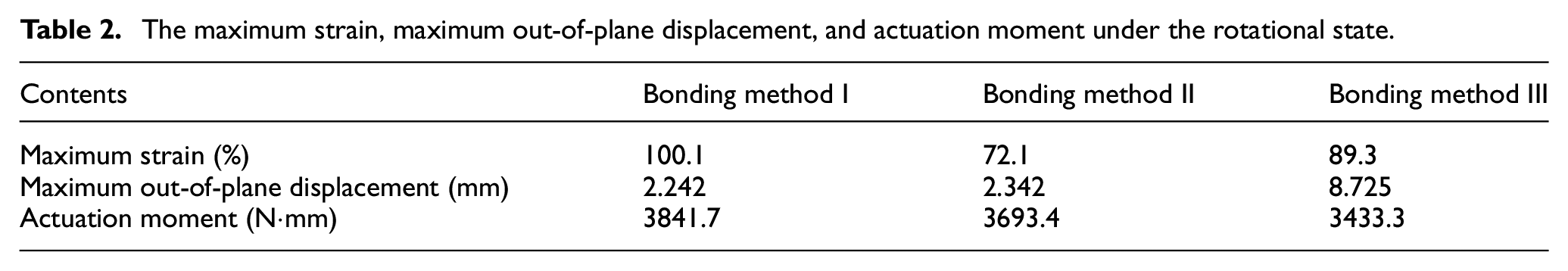
Under the rotational state, the maximum strain of the face-sheet, the maximum out-of-plane displacement, and the actuation moment of the unit cell are illustrated in Table 2. Similar conclusions can be drawn: among the three bonding methods, bonding method II shows the lowest strain values, and its maximum out-of-plane displacement closely matches that of bonding method I. Although the actuation moment of bonding method III is the smallest, excessive out-of-plane displacement of the face-sheet is caused by the large unbonded area. For bonding method III, it is not worth sacrificing out-of-plane smoothness to improve actuation performance.
The maximum strain, maximum out-of-plane displacement, and actuation moment under the rotational state.
3.3. The optimization design of the connection area for variable-sweep structure
The studies have shown that sandwich-flexible-skin has been widely used in the aviation field due to its high out-of-plane stiffness and good airtightness (Vocke et al., 2011; You et al., 2020). In Figure 17, a variable-sweep structure for UAVs is designed to assess the feasibility of the proposed method in engineering. The dimensions of the configuration are obtained by scaling down the original structure. The complete structure consists of a support skeleton and a silicone rubber face-sheet bonded to the outer surface of the skeleton. The skeleton is arranged in an Ω-shaped unit-cell pattern and curved into a streamlined shape resembling a flattened U-shape. Due to the irregularity of the geometric dimensions, achieving a neat and orderly arrangement of the cells is challenging. Consequently, smooth spline curves are employed to connect them at specific boundaries. This structure resembles a sleeve positioned at the junction of the fuselage and wings, facilitating smooth transition.
The variable-sweep structure.
The structural boundary conditions are illustrated in Figure 18. The long side of the structure remains fixed, and the short side is coupled to the center point. The center point is moved along the X, Y-axis and rotated around the Z-axis. The internal surface of the skeleton is constrained in the movement along the Z-axis, as well as in the rotation around the X- and Y-axis, while a pressure is applied to the inner surface of the face-sheet.
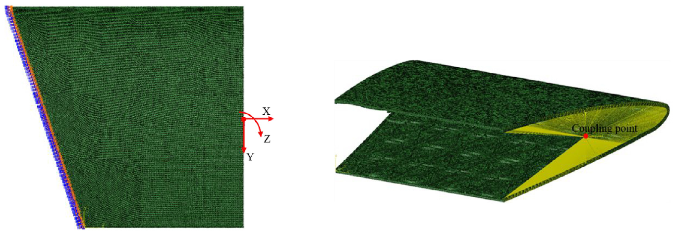
The boundary conditions of the variable-sweep structure.
The connection areas between the face-sheet and the skeleton require different connection layouts for different morphing types. The morphing of unit-cells in different areas is not the same, so it is necessary to identify the morphing types in different areas and then choose the optimal connection layout.
After observing the boundary conditions of Figure 18, the combined morphing is simplified into tension-dominated and rotation-dominated morphing. The motion boundary involves rotational movement around the Z-axis, resulting in adjacent unit cells exhibiting the rotational state, and the unit cells away from the motion boundary are considered to be predominantly in a tensile state. The specific distribution of connection areas is observed in Figure 19. The distribution in the red box corresponds to the topology structure in the rotational state, as shown in Figure 13(b), while the remaining area represents the topology structure in the tensile state, as depicted in Figure 8(b).
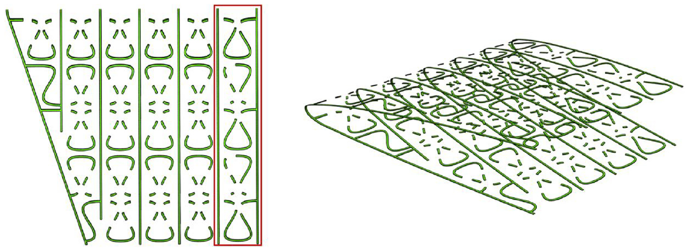
The distribution of the connection areas between the face-sheet and the skeleton.
The parameters of the boundary condition are listed in Table 3. After substituting the connection area shown in Figure 19 into the variable-sweep structure, the results of strain and out-of-plane displacement are shown in Figure 20.
The parameters of the boundary conditions.
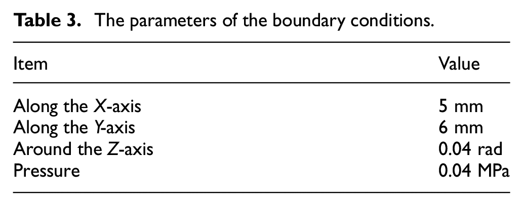
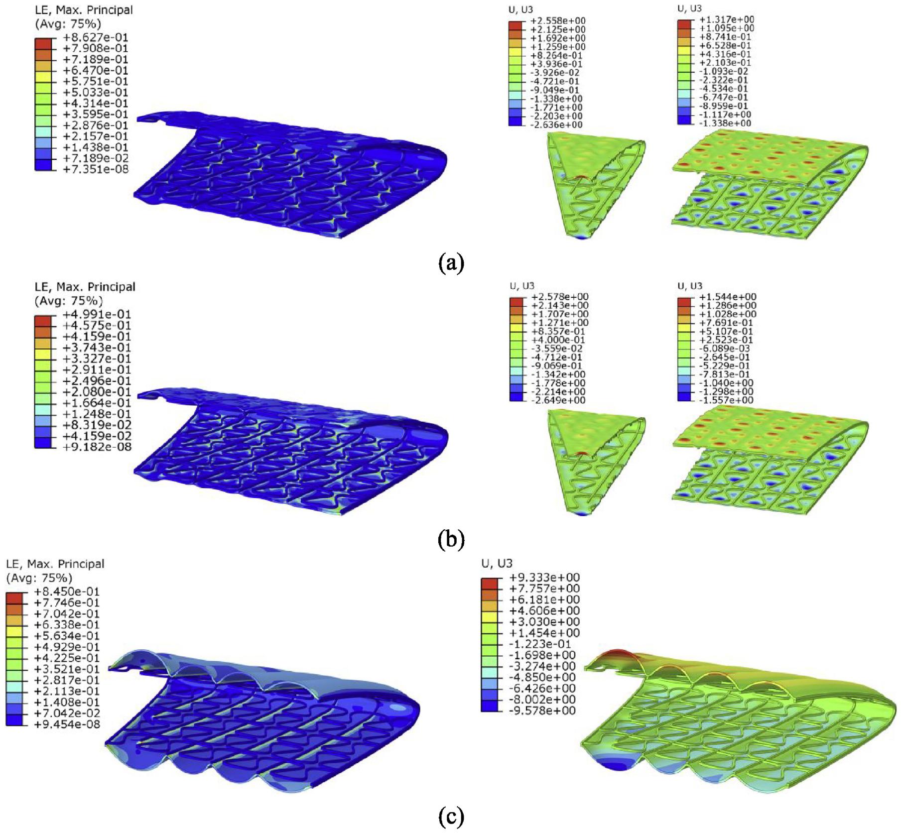
The strain (left) and out-of-plane displacement (right) of the variable-sweep structure: (a) bonding method I, (b) bonding method II, (c) bonding method III.
Compared with the other two bonding methods, the maximum strain in the bonding method II is significantly decreased, with no excessive increase in the out-of-plane displacement of the face-sheet, indicating that the design of the connection area is reasonable. In the bonding method III, the strain in most areas of the face-sheet remains at a low level, but the excessive out-of-plane displacement leads to an increase in the strain value at the connection with the straight beams. Additionally, the actuation load of the bonding method II is intermediate among the three. According to the previously mentioned evaluation criteria priorities, the bonding method II is the optimal connection layout.
To increase the magnitude of motion of the structure, the boundary condition parameters are set as follows: the center point undergoes a displacement of 25 mm along the X-axis, 30 mm along the Y-axis, and a rotation of 0.2 radians around the Z-axis, while a pressure of 0.04 MPa is applied to the inner surface of the face-sheet. The strain and out-of-plane displacement distribution of the face-sheet are depicted in Figure 21. To accurately assess the magnitude of structural morphing, a simplified diagram illustrating the before and after morphing motion projected onto the X–Y plane is presented in Figure 22. The solid lines represent the original contour of the structure, while the dashed lines represent the morphing state. The simulation result indicates that the sweep angle of the structure can reach 8.95°, resulting in approximately 27.3% elongation at the leading edge. Additionally, the maximum strain of the face-sheet is 143.2%. Previous research has indicated that if the out-of-plane displacement is less than 2.54 mm, the negative impact on aerodynamic performance is minimal (Murray et al., 2010; Vocke et al., 2011), so this out-of-plane displacement value is used as a design reference herein. The maximum out-of-plane displacement in Figure 21(b) is 2.75 mm, an increase of only 8.3% compared to this level. Some potential methods can be used to reduce the out-of-plane displacement, such as adjusting the details of the substructure or applying pretension to the face-sheet.
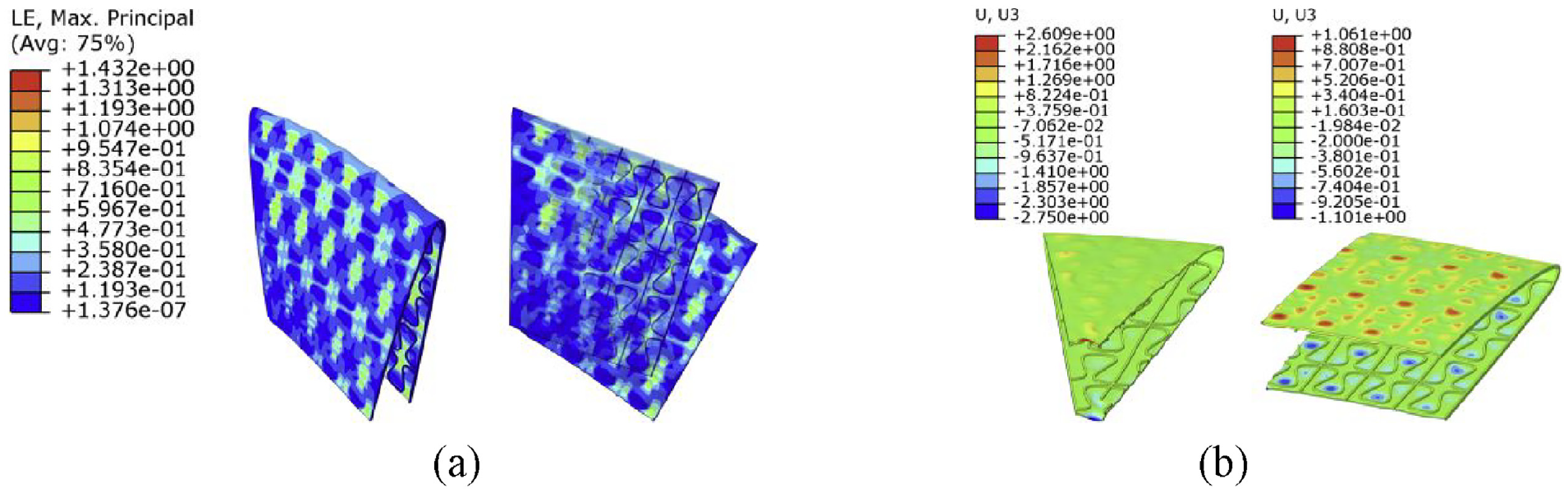
Strain and out-of-plane displacement of the variable-sweep structure: (a) strain, (b) out-of-plane displacement.
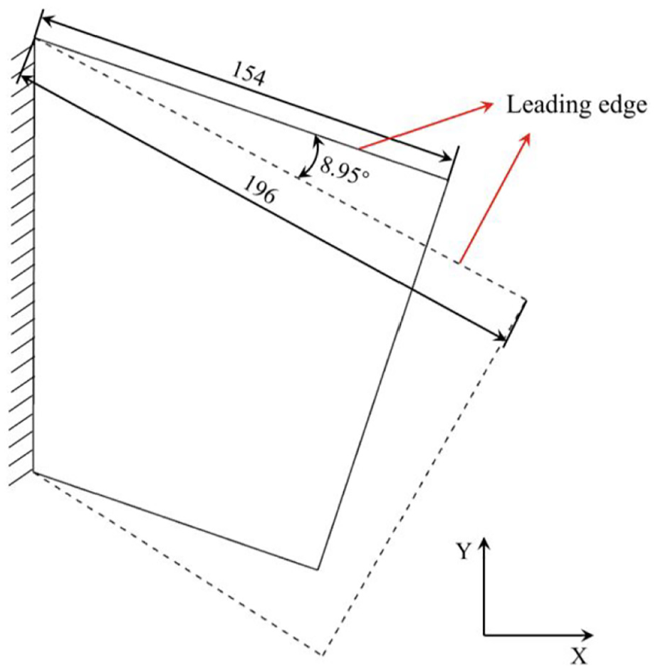
Schematic diagram of the structure’s profile before and after morphing.
Analyzing the simulation result of the scaled-down structure provides valuable insights for the treatment of the actual structure. If the real structure is handled using the proposed method, the strategies can be utilized such as reducing the size of the unit cells or increasing their distribution. Depending on the cumulative morphing effect of unit cells, larger sweep angle and leading-edge morphing can be achieved without compromising the maximum strain of the face-sheet.
4. Conclusions
In this paper, a topology optimization-based method is proposed to address the strain concentration in flexible skins. In this method, the connection areas between the face-sheet and the support skeleton are considered as the virtual adhesion layer comprising of adhesion materials. The distribution of connection areas is described by allocating the presence and absence of the adhesion material. The optimization model is established with minimizing the globe stress of the face-sheet as the objective function, the volume fraction of the design domain as the constraint. The tensile and rotational states of the flexible skin with Ω-shaped honeycombs are analyzed in detail. The optimization results show that the optimized face-sheet exhibits a significant reduction in strain for both tensile and rotational states.
Furthermore, a scaled-down structure for variable sweep wings in UAVs is designed. Based on the specified boundary conditions, the structure can achieve a sweep angle of 8.95° and a leading edge morphing of 27.3%. It should be noted that this scaled-down structure is only used to further verify the effectiveness and practicality of the proposed method. In practical application, more significant sweep angle morphing can be achieved by reducing the size of unit cells or increasing the number of unit-cells, capitalizing on the cumulative morphing effect of the cells. Ultimately, it is expected that the optimization method and the variable sweep structure developed in this study will provide valuable insights and contribute to advancements in the field of morphing wings.
Footnotes
Declaration of conflicting interests
The authors declared no potential conflicts of interest with respect to the research, authorship, and/or publication of this article.
Funding
The authors disclosed receipt of the following financial support for the research, authorship, and/or publication of this article: This work is financially supported by the National Natural Science Foundation of China (U2341232, 12272076) and the 111 Project (B14013). These financial supports are acknowledged.
Data availability statement
Data sharing not applicable to this article as no datasets were generated or analyzed during the current study.