
Abstract
Vibration control remains a pivotal challenge in engineering, demanding solutions that offer wideband and low-frequency effectiveness with minimal energy. This paper introduces a hybrid vibration control method, combining semi-active piezoelectric (Piezo), and passive acoustic black hole (ABH) techniques. The semi-active approach, similar to Bang-Bang control, efficiently curtails low-frequency vibrations without precise control modes, using scant external energy. Concurrently, passive strategies exploit the ABH effect to absorb medium-high frequency waves through focused damping. The integration of Piezoelectric integrated ABH (Piezo-ABH) structures showcases the feasibility of broad-spectrum vibration dampening, with experimental outcomes revealing significant vibration reduction across 20 ∼ 2000 Hz, averaging an 8.0 dB decrease.
Keywords
1. Introduction
Structures with highly-damped properties have potential applications in mechanical engineering field, especially in vehicles, aircrafts, etc. Utilizing viscoelastic materials is a common way to provide to this demand. Such materials are usually bonded to structural surface over a large area to enhance the structural damping. However, additional weight and poor performance in low-frequency vibration significantly limit their applications in damping vibrations for lightweight structures. Acoustic Black Holes (ABHs) structures, a passive vibration control innovation, offer a promising alternative (Pelat et al., 2020). ABHs, with their power-law tapering thickness, slow and amplify flexural waves, localizing energy for effective dissipation by strategically placed damping materials (Krylov, 2007, 2020; O’Boy and Krylov, 2011). This technique presents an effective strategy for managing flexural vibrations in thin-walled structures, potentially enabling weight savings.
In the past decade, detailed analyses of ABH structures have significantly advanced our understanding of their properties. This progress encompasses semi-analytical models (Lee and Jeon, 2019; Tang et al., 2016), the use of the Gaussian Expansion Method (GEM) to capture local modes (Deng et al., 2019), and the application of the Component Mode Synthesis (CMS) method to address dynamic coupling (Deng et al., 2022). An additional ABH structure was proposed to enhance its engineering applicability while maintaining the integrity of the host structure (Ji et al., 2021). Their experimental and theoretical analyses demonstrated that this design efficiently transfers, absorbs, and dissipates vibrational energy, enabling effective broadband vibration suppression. ABHs not only reduce structural vibrations but also aid in noise suppression (Lu et al., 2024; Tang et al., 2023; Wang et al., 2019), and energy harvesting, as demonstrated through numerical simulations and experimental validations (Zhao et al., 2014, 2015). Although ABH structures offer significant advantages in energy concentration and damping enhancement at mid-to-high frequencies, their geometric design is constrained by the load-bearing requirements and size limitations of the host structure. As a result, their effective frequency range is limited, particularly in terms of vibration suppression performance at lower frequencies (Denis et al., 2014; Feurtado, 2016). Efforts have been made to lower the cut-on frequency through strategic parameter adjustments and design modifications (Lee and Jeon, 2017; Tang and Cheng, 2017a). With finite-size structures featuring periodic ABH elements (Ji et al., 2022; Tang and Cheng, 2017b) and three-dimensional lightweight lattice structure designs, there is clear potential to overcome these limitations (Ye et al., 2023). These advancements mark significant progress in extending ABH applications, although practical implementation remains occasionally constrained by the size of the host structure.
Nonlinear systems, with their inherent ability to generate harmonics and facilitate energy transfer from low to higher-order frequencies, offer a promising solution for addressing low-frequency vibration control challenges in ABH structures. Previous research has explored various approaches, including introducing geometrical nonlinearities, and applying vibro-impactors to induce mechanical nonlinearities in ABH beams, thereby enabling effective energy transfer (Denis et al., 2014; Feurtado, 2016; Tang and Cheng, 2017a). However, a significant practical challenge arises in realizing these nonlinearities, casting uncertainty on the feasibility of such designs due to constraints in space and control complexities.
Piezo control schemes in plate structures, which yielded significant low-frequency suppression (Hook et al., 2022). However, the complexity, high energy consumption, and cost associated with the extensive control loops and power supplies became problematic. In contrast, semi-active control provides a more straightforward and energy-efficient solution for low-frequency suppression, utilizing Piezo materials to adjust the structural stiffness without requiring substantial energy consumption. This approach, akin to the Bang-Bang algorithm, simplifies implementation while effectively managing low-frequency vibrations (Badel et al., 2006; Ji et al., 2016; Qiu et al., 2009; Wu et al., 2012, 2022). However, it introduces challenges like nonlinear signal generation and harmonic components, complicating broadband control.
This paper proposes an innovative approach for wide-frequency vibration suppression by integrating semi-active control’s nonlinear properties and low-frequency modal effects with ABH’s high-frequency energy manipulation capabilities. The methodology for broad frequency vibration control through a Piezo-ABH structures is detailed, encompassing strategies for low to medium-high frequency management. Performance evaluation employs diverse excitation forms, analyzing structural responses and control effectiveness. The study concludes with insights into the approach’s efficiency and potential improvements, setting a foundation for future exploration in vibration control technologies.
2. Functional principles of wideband frequency vibration control
2.1. Design concept of a Piezo-ABH structures
A Piezo-ABH structures comprises an ABH beam outfitted with Piezo elements aligned along the beam and integrated with semi-active control circuits, as depicted in Figure 1. As shown in the Figure 1, a uniform steel beam with thickness h2, length L, and width b is used as the main structure, with an embedded ABH section designed and fabricated. In this configuration, the ABH section has a length lABH, and its thickness gradually tapers along the beam length, following a power-law profile from h2 to h1. Piezo ceramics, each of thickness h p , are symmetrically affixed to the beam’s upper and lower surfaces near the clamped end. The semi-active control electrical circuits are connected at either end of these Piezo layers. Additionally, a damping layer of thickness h d is assimilated within the ABH. The system is subjected to flexural vibrations induced by an external sectional force fext (t) at the fixed end.
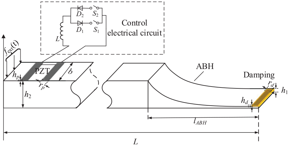
Piezo-ABH beam with control system and a damping material at its tip end.
An external switch circuit is linked to the Piezo components, constituting a semi-active vibration control system. The ABH structure and the synchronized switch damping circuit are engineered to fulfill distinct roles. In the following sections, we will delve into the medium-high frequency damping capabilities of the ABH and the semi-active control attributes of the electromechanical mode, respectively.
2.2. Mid-high frequency vibration suppression
The propagation characteristics of bending waves in a one-dimensional ABH structure with exponentially varying thickness along the X-axis, as depicted in Figure 2, are first recalled (Krylov, 2020).
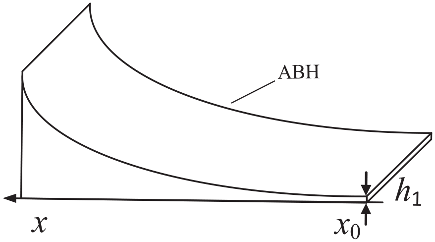
Geometry of a power-law profile; a truncation is located x0.
The one-dimensional beam of a free wedge, characterized by a thickness that follows a power-law distribution, can be described as

where m is a positive rational number, x0 is the truncation position, h1 is the truncation thickness of the ABH, and ε is a dimensional parameter. The governing equation (2) of the bending wave in the power-law structure can be cast into the following form,
where

A(x) is the amplitude magnitude of the wave. The flexural wave phase Φ from an arbitrary point x located in the wedge medium to the wedge tip (x0) expressed in equation (4).
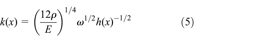
The local wavenumber k(x) of a flexural wave is given in equation (5).
When the power index m ≥ 2, the cumulative phase Φ tends to infinity, resulting in the concentration of the bending wave at the structure’s edge. As the flexural wave propagates toward the sharp edge of an elastic wedge, it decelerates and its amplitude increases. This phenomenon occurs only when the wavelength of the bending wave is smaller than the size of the ABH structures. In other words, the ABH structure’s aggregation effect has a specific frequency range within which it is effective. This range is typically characterized by the cut-on frequency, which is primarily influenced by the geometry and material properties of the ABH (Sun et al., 2024).
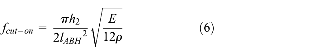
The lABH is the length of the wedge surface corresponding to the x-direction. In the region of energy convergence, strategically positioning damping materials along the edges can significantly mitigate structural vibrations (Mironov, 1988). Consequently, when utilizing the ABH effect for vibration mitigation, the focus primarily shifts towards attenuating mid to high-frequency vibrations. However, it is important to note that low-frequency vibrations, typically larger than high-frequency ones, pose a greater risk to the structural integrity due to fatigue. These should therefore receive considerably more attention.
2.3. Low-frequency vibration mitigation
Figure 3 delineates the SSDI (Synchronized Switch Damping based on Inductor) technique’s schematic, a renowned semi-active method for vibration control (Lefeuvre et al., 2006). The switching apparatus is an assembly of two diodes, D1 and D2, alongside two switches, S1 and S2, all in series with an inductor, denoted by L. This device is actuated at the displacement extremes. Figure 3(a and b) depict the dual-phase operational principle within one semi-period, while Figure 3(c) illustrates the theoretical Piezo voltage and displacement waveforms.
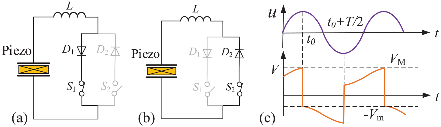
SSDI electrical circuit: stage 1: Switch S2 is opened and switch S1 is closed at the moment when the displacement reaches a maximum (a); stage 2: Switch S1 is opened and switch S2 is closed at the moment when the displacement reaches a minimum (b); and the corresponding waveforms of displacement u, voltage V (c).
Prior to Stage 1 (0 < t < t0), with the displacement u on the rise, the switches are configured as follows: S1 is disengaged, and S2 is disengaged, resulting in the Piezo element being in an open-circuit state. Consequently, the voltage V remains in synchrony with the displacement u.
Stage 1 commences with the peak displacement (concomitantly, the voltage across the Piezo element peaks as both are synchronous); at which point, S2 disengages while S1 engages. Consequently, diode D1 becomes conductive, thereby linking the inductor L with the Piezo component. The Piezo patch, referred to as C0 representing the capacitance, in tandem with the inductor L, forms an L-C0 resonance circuit capable of rapidly inverting the voltage across the Piezo patch. Given the capacitive nature of the Piezo element, this segment of the circuit temporarily functions as an oscillating system. The engaged state of switch S1 is maintained for a duration time, equating to half the pseudo-period of the L-C0 circuit, as specified in equation (7).

V m and V M , as depicted in Figure 3(c), are the voltages before and after the oscillation cycle, respectively. The relationship between V m and V M can be mathematically expressed by equation (8).

where γ is the inversion factor of the SSDI technique, it only depends on the quality factor Q e of the electric oscillator.
When entering stage 2, as illustrated in Figure 3(b), the configuration reverses: switch S2 is now engaged and switch S1 is disengaged. It is at this phase that the displacement reaches a minimum. During this interval, the Piezo patch in conjunction with the inductor once again forms an L-C0 resonance circuit. The rapid inversion of the voltage across the Piezo patch during stage 2 mirrors the process observed in stage 1.
As shown in the displacement and voltage waveform diagram in Figure 3(c), when the control system captures the structural vibration displacement signal, it switches the circuit based on the displacement extremum information. The Piezo patch forms an oscillating circuit with the inductor in the circuit, not only achieving the polarity reversal of the Piezo control voltage but also ensuring that the control force generated by the Piezo always opposes the velocity of the structure’s vibration, achieving vibration suppression. Additionally, utilizing the L-C0 oscillation characteristics can effectively amplify the voltage across the Piezo patch, thereby enhancing the control effect. Since the voltage switching is based on the extremum of structural vibration displacement, even if the frequency of the structural vibration changes, as long as the system follows and captures the structural vibration displacement information, precise control can still be achieved. Therefore, semi-active technology exhibit better robustness compared to traditional passive control systems. Furthermore, the oscillating circuit formed by the Piezo patch and the inductor in the circuit can effectively amplify the voltage across the Piezo patch, with the amplitude of the Piezo voltage primarily dependent on the system’s quality factor. However, if the structural vibration response is very complex, with many modal or wide-frequency vibrations, frequent switching based on detected displacement extrema can lead to significant energy loss and a reduction in the system’s quality factor, thus degrading the control effect. Semi-active control methods are more suitable for handling situations with single structural modes or using switching algorithms to control several modal frequencies. Moreover, it is worth noting that the voltage output by the Piezo patch is similar to a square wave signal. The higher harmonic energy contained in the square wave signal can cause additional high-frequency vibrations in the structure, which is a drawback of semi-active control.
2.4. Wideband vibration mitigation
The combination of semi-active control techniques and ABH technology offers a unified and effective approach for comprehensive vibration damping across the entire frequency spectrum. As shown in Figure 4, this integrated approach divides the frequency response of the structural system into low and mid-high frequency ranges, with the cut-on frequency of the ABH structure acting as the boundary. Below the cut-on frequency, semi-active control is used to suppress the low-order modal vibrations of the structure. In the mid-high frequency range, the ABH structure plays a crucial role by concentrating and effectively dissipating high-frequency vibration energy, thus solving the potential issue of nonlinear energy overflow in traditional semi-active control. The strategic combination of these control methods significantly improves vibration management across a wide frequency range, and the ABH structure is simple to design and easy to implement in engineering. Its effectiveness will be further verified through experimental testing.
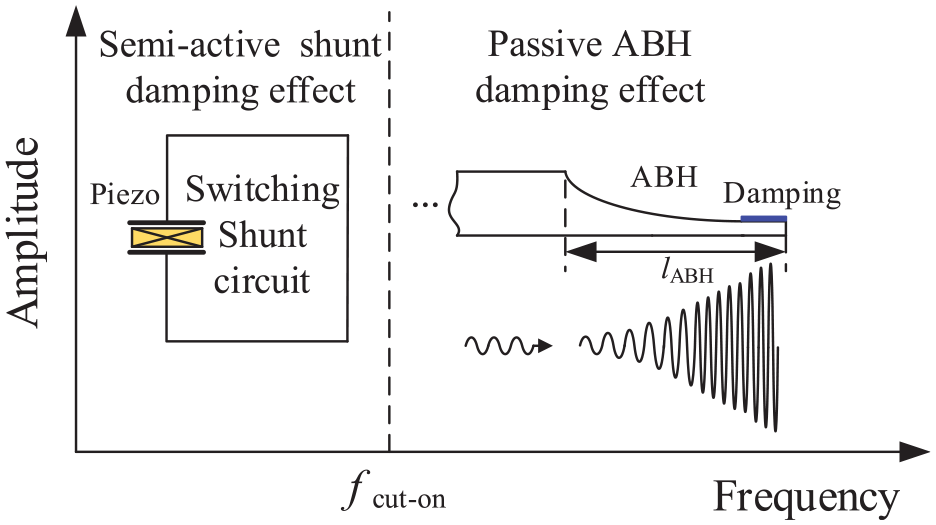
Coupling vibration control principle.
3. Experimental results and analysis
3.1. Experimental setup
The experimental system setup is shown in Figure 5: the controlled object is a steel ABH beam, and Table 1 provides the structural dimensions and material parameters. Figure 5(c) shows a physical image of the ABH cantilever beam structure, where the blue dashed box indicates the ABH region. The surface of the ABH beam is pre-treated with material deposition: damping material is applied to the location indicated by the green dashed box at the end of the structure, while Piezo patches are adhered to the location indicated by the red dashed line on the upper surface. The Piezo patches are connected in parallel and externally connected to a control circuit. Based on the real-time control system schematic shown in Figure 5(d), the structure displacement information is utilized to generate a switching signal, controlling the on/off state of the switch in the control circuit. The numerical filter, indicated by the red solid box, primarily filters out environmental interference signals, thereby enhancing the accuracy of the modal displacement peak value identification for the controlled structure.
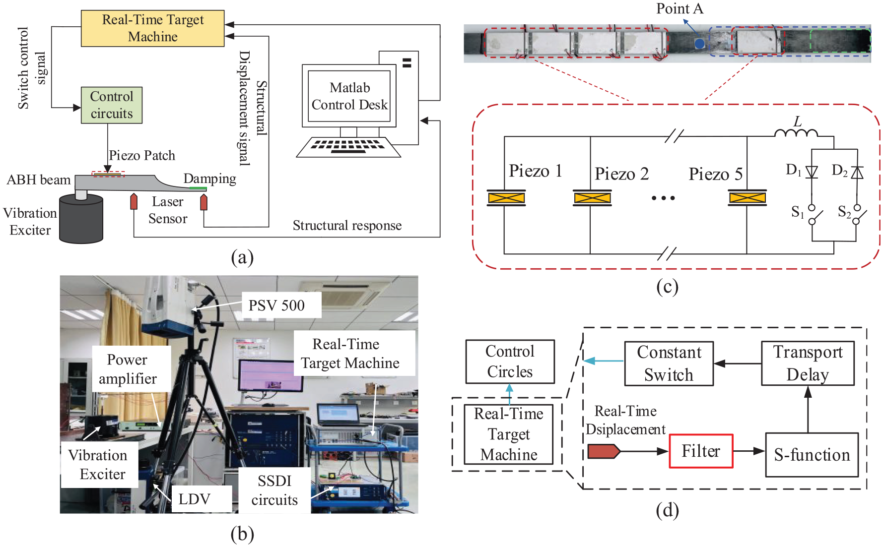
Schematic diagram (a), experiment equipment setup of the system (b), the details of the Piezo-ABH beam (c), displacement data process in the real-time target machine (d).
Material and geometrical parameters of beam, Piezo, damping, and, semi-active circuit.
To further investigate the broadband control effectiveness of the integrated Piezo-ABH beam, the control effect under different configuration states is compared, including whether or not damping energy dissipation materials are present in the end region of the ABH beam, and whether the Piezo patch is connected or disconnected from the external control circuit. An experimental system is constructed based on the schematic diagram shown in Figure 5(a), as illustrated in Figure 5(b). An exciter (B&K 4809) simulates the external excitation applied to the end of the structure. The structure displacement signal acquired by the Laser Doppler velocimetry (OFV-505) is transmitted to the real-time control system (Speedgoat). The external circuit is switched between connected and disconnected states based on the displacement peak value signal output by the real-time control system. Meanwhile, the control effectiveness of different schemes is evaluated based on the detected displacement signal. The entire control system primarily utilizes a three-point extremum detection method to automatically acquire the peak displacement of the structure. Based on the peak information, the system dynamically adjusts the state of the circuit switches. This process requires only minimal power supply for the control circuit board, resulting in extremely low energy consumption. It is characterized by low energy usage, simplicity in operation, and system stability.
3.2. Open-circuit characteristics in a Piezo-ABH beam
To understand the structural characteristics of the Piezo-ABH beam, the external control circuit was disconnected in advance to analyze the vibration characteristics of the structure. In the experiment, a random white noise signal with a frequency range of 20 ∼ 2000 Hz was applied as the excitation source at the fixed end of the Piezo-ABH beam. A laser sensor was used to capture the vibration response spectrum at point A, located 200 mm away from the constrained end. To minimize the impact of environmental noise and other interferences during the experiment, 20 tests were conducted on the collected single-point frequency response data, and the results were averaged. As shown in Figure 6(a), the structural vibration response data is clearly distinguishable. The figure shows two scenarios: The structure’s end is without any damping material (Black Curve). Damping material is applied at the structure’s end (Blue Curve). This allows us to compare the vibration response of the structure with and without damping material. Comparing these two scenarios, the average peak value of the modal velocity response of the structure is reduced by 7.3 dB within the 20 ∼ 2000 Hz range. The activation frequency of the ABH structure, calculated using equation (6), is 467 Hz. This observation indicates that the ABH damping effect significantly suppresses structural vibration within its effective working frequency range. Within the frequency range below the activation frequency, the first mode response of the structure remains largely unchanged. However, the amplitude of the velocity response at the second, third, and fourth modal frequencies is reduced by 3.6, 3.2, and 11.6 dB respectively. To analyze the modal characteristics of the structure, surface displacement response signals (
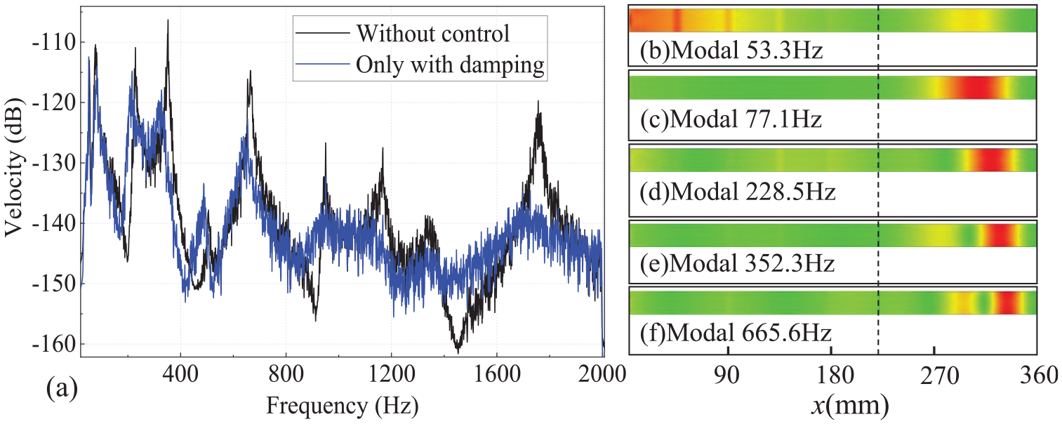
Velocity response of the ABH beam with or without damping layer (a), and corresponding to the stress of the first fifth-order ABH beam structure (b–f).
Based on the frequency response analysis of the open-circuit Piezo-ABH beam, the damping material placed in the ABH region is unable to effectively suppress the first mode vibration. As shown in Figure 6, the vibrational response of the structure’s first mode is significant and cannot be neglected. The following section will focus on vibration control of the first mode of the Piezo-ABH beam. By activating the external circuit, we will investigate the effectiveness of a hybrid vibration control method incorporating semi-active control and ABH damping effects. Experimental phenomena will also be analyzed.
3.3. Hybrid vibration control effects
This study investigates the effectiveness of semi-active control in suppressing low-frequency vibrations in a Piezo-ABH beam, applying a single-frequency excitation, and analyzing changes in structural response and variation in energy levels. The study also evaluates the effectiveness of the hybrid vibration control method in suppressing vibrations over a wide frequency range, considering added damping. Based on the research objectives outlined above, experiments were conducted with two different forms of excitation signals: fixed-frequency excitation and random load excitation, designated as Case 1 and Case 2.
Case 1
The first mode of the Piezo-ABH beam structure was chosen as the target for vibration control. An electromagnetic shaker generated a sinusoidal excitation signal with a frequency component of 53 Hz, which was applied to the clamped end of the beam.
Case 2
A band-limited white noise signal with a frequency range from 20 to 2000 Hz was generated by an electromagnetic shaker and applied to the clamped end of the Piezo-ABH beam.
3.3.1. Periodic sinusoidal excitation
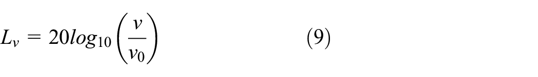
In Case 1, without damping, Figure 7(c) illustrates that increasing the number of piezoelectric patches connected in parallel to the control circuit from two to five reduces the amplitude of the structure’s first modal vibration response by 4.2 and 10.5 dB, respectively, while also introducing complex harmonic energy components. To analyze the harmonic energy components within the structure, a time-domain analysis was performed under conditions where five piezoelectric patches were connected in parallel, with the external control circuit either engaged or disconnected. The displacement and voltage output waveforms at the structure’s end were extracted, as shown in Figure 7(a and b). When control was activated, the Piezo voltage signal shifted from a sinusoidal waveform with a peak-to-peak value of ±21 V to a quasi-square waveform with an amplitude of ±108 V. Simultaneously, control reduced the peak-to-peak value of the displacement signal from ±0.35 to ±0.09 mm, introducing spikes in the displacement signal. This indicates that as the Piezo drive signal transitioned from a sine wave to a quasi-square wave, the driving force effectively suppressed low-frequency vibrations but inevitably introduced substantial harmonic energy within the high-frequency range of the structure. Notably, as shown in Figure 7(c), the harmonic frequency at 1770 Hz couples with the structural modal frequency, triggering a modal response in the structure. Additionally, when five piezoelectric patches are connected in parallel, the frequency response amplitude at 1770 Hz is 4.5 dB higher than when only two patches are used. This indicates that as more Piezo patches are added to the control system, semi-active control enhances low-frequency vibration suppression but also leads to increased harmonic energy overflow within the structure. The structural energy levels before and after control are evaluated based on the energy level formula in equation (9), where v represents the structural velocity response, and v0 is the reference velocity (10−3 m/s).
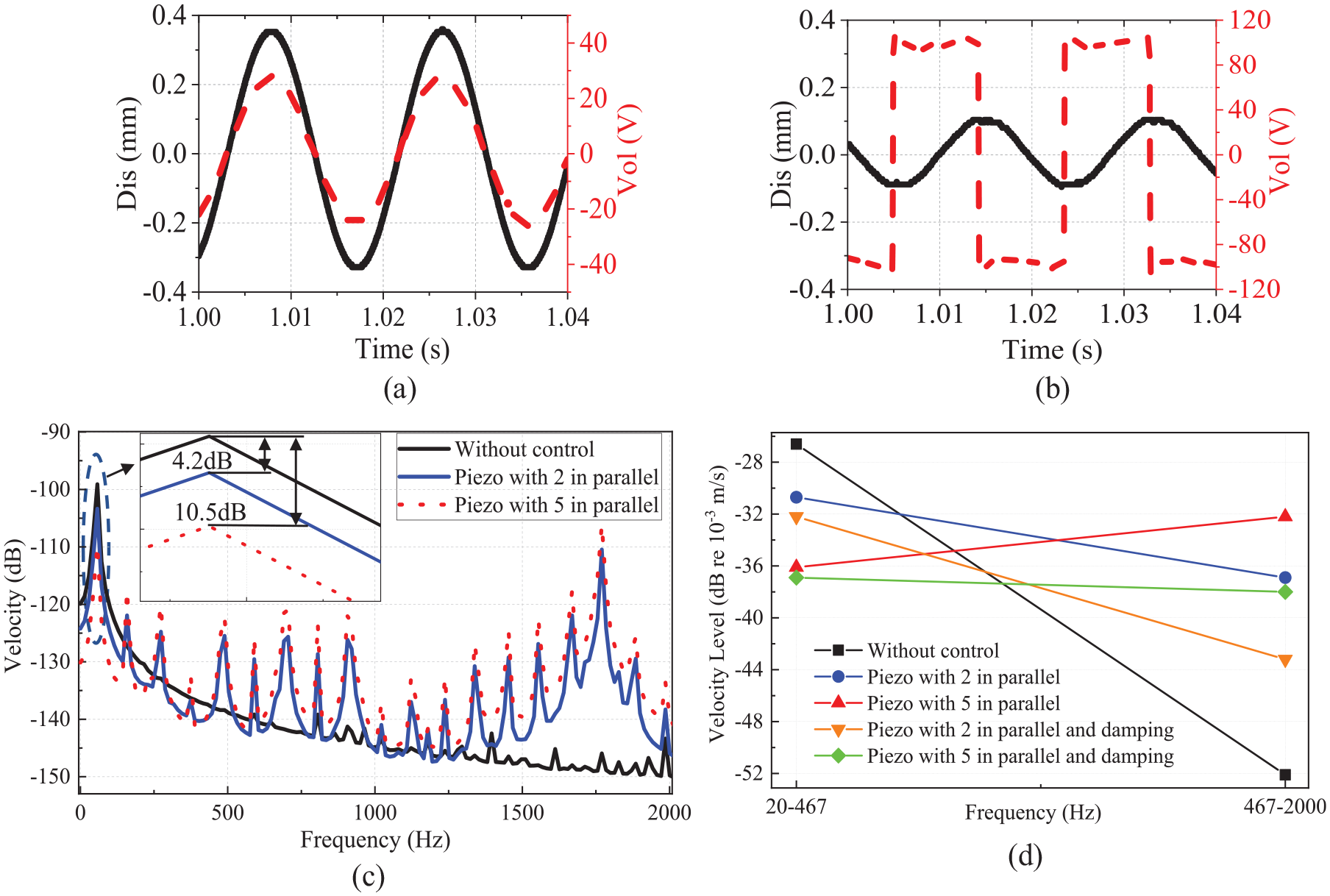
The corresponding waveforms of displacement and Piezo voltage without techniques control (a) and with control (b), frequency responded of the Piezo integrated ABH beam with different numbers of Piezo in control (c), Velocity level variation with control methods and piezoelectric element quantities (d).
To separately assess the structural energy level changes induced by semi-active control and ABH damping effects, the 20 ∼ 2000 Hz frequency range is divided into low-frequency (20 ∼ 467 Hz) and high-frequency (467 ∼ 2000 Hz) bands based on the characteristic frequency of the embedded ABH structure. The energy level changes in each frequency band of the structure are compared under different control methods and numbers of piezoelectric elements. As shown in Figure 7(d), under Semi-active vibration control, when two and five piezoelectric elements are connected in parallel, the vibration energy level in the low-frequency band decreases by 5.6 and 10.3 dB, respectively, while the harmonic energy in the high-frequency band causes the vibration energy level to increase by 8.9 and 14.1 dB, respectively. This demonstrates that optimizing the number of Piezo elements connected affects low-frequency control performance to some extent, while also increasing the overflow effect of harmonic energy. In the experimental conditions shown in Figure 7(d), where five Piezo devices are used for parallel control of the ABH cantilever beam, the vibration energy level in the mid-to-high frequency range of the structure decreased by 5.8 dB with damping material (60 × 20 × 2 mm) applied at the beam’s end. This indicates that the ABH structure is effective in gathering and efficiently dissipating the harmonic energy within the structure. Under the Piezo-ABH hybrid control, in the 20 ∼ 2000 Hz frequency range, the vibration energy levels of the structure change by 3.3 and 3.8 dB, respectively, when two and five Piezo elements are connected in parallel, showing a minimal overall difference in energy levels. To ensure effective low-frequency control, subsequent experiments will use five Piezo elements in parallel.
The observed changes in the Piezo-ABH beam’s displacement amplitude demonstrate the effectiveness of the semi-active control method in suppressing low-frequency vibrations. The voltage switching across the Piezo patch reveals the energy transfer mechanism during the control process. Preliminary investigations under single-frequency excitation have validated the ability of the ABH structure to effectively dissipate the high-frequency vibrational energy transferred during control. The effectiveness of this hybrid vibration control approach will be further investigated under broadband excitation conditions.
3.3.2. Experimental evaluation with band-limited white noise excitation
Although Case 1 demonstrates the effectiveness of the semi-active control method in suppressing low-frequency vibrations, a complex vibration environment can interfere with the control system’s ability to identify the target frequency signal, thereby impacting control performance. By adding a band-pass filter (20 ∼ 70 Hz) to the real-time control system shown in Figure 5(d), interference frequencies were effectively filtered out, enhancing the accuracy of displacement signal acquisition at the target frequency. Figure 8 presents the vibration response at point A of the structure, measured within the 20 ∼ 2000 Hz frequency band under the load excitation described in Case 2. Figure 8(a) compares the structural response across a broad frequency range under semi-active control. The zoomed-in portion highlighted by the yellow dashed box reveals a 10.5 dB reduction in the response amplitude at the structure’s first mode. While the response amplitudes at several other modal frequencies slightly increased, such as the approximately 4 dB peak amplitude increase at the tenth mode highlighted by the green dashed box. This phenomenon can be attributed to coupling between the resonant frequencies generated by the semi-active control and the structural modal frequencies across the broadband range.
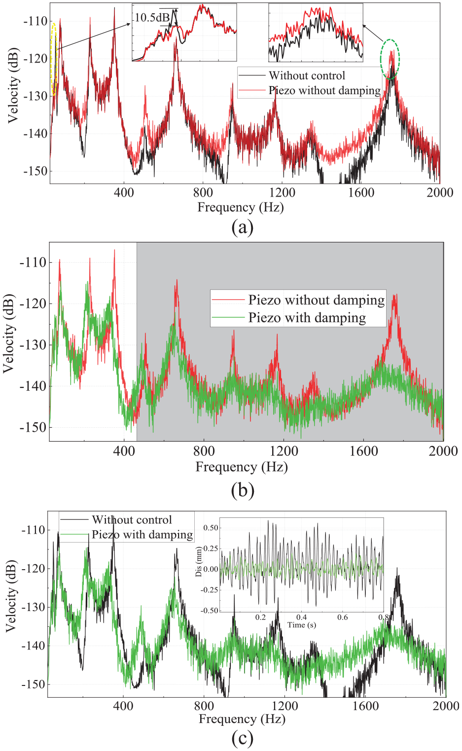
Switching shunt damping circuit control response of Piezo-ABH beam (a), responded of a Piezo-ABH beam with or without damping (b), respond of hybrid control strategy in frequency and time domain (c).
During semi-active control, as shown in Figure 8(b), the damping material attached to the end of the ABH structure effectively reduces the average modal peak amplitude by 9.3 dB within the 20 ∼ 2000 Hz range. In the shaded region of the figure (467 ∼ 2000 Hz frequency range), the structural energy level decreases by an additional 4.8 dB. This demonstrates that the damping effect of the ABH structure effectively suppresses the mid- to high-frequency structural modal responses generated by both external excitation and semi-active control. Figure 8(c) shows that, without control, the addition of damping and the implementation of semi-active control reduce the first modal vibration amplitude of the structure by 12.7 dB, with an average reduction of 8.0 dB in the major peak amplitudes across the entire frequency range. During the 0 to 0 ∼ 8 s interval, the peak-to-peak amplitude of the average structural displacement decreases from ±0.4 mm to ±0.094 mm. This significant reduction in vibration, achieved through the combined effects of ABH damping and semi-active control, highlights the effectiveness of the proposed hybrid vibration control method in achieving substantial suppression across a wide frequency spectrum.
3.4. Hybrid vibration control performance of a uniform beam
This study utilized a uniform steel beam with identical geometry and thickness. To investigate the universality of high-order harmonic generation by semi-active control and the unique damping properties of the ABH structure, vibration experiments were conducted under both Case 1 and Case 2 conditions using a low-pass filter (cut-off frequency: 50 Hz) as depicted in Figure 5(b). The vibration response at the center of the beam’s upper surface, located 200 mm from the fixed end, was extracted and analyzed for comparison.
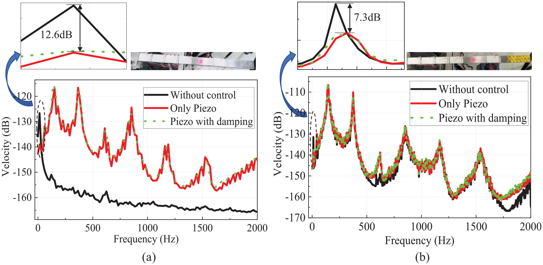
Similar to the Piezo-ABH beam, five identical piezoelectric patches were attached to the surface of the uniform beam and connected in parallel to the control circuit. A sinusoidal excitation signal with a frequency of 15 Hz was applied at the fixed end of the piezoelectric uniform beam to excite the first-order modal response. As shown in Figure 9(a), after applying piezoelectric control, the amplitude of the first-order modal vibration of the structure was reduced by 12.6 dB. However, during the piezoelectric semi-active control process, energy overflowed and shifted to the mid- and high-frequency ranges, leading to a more pronounced response in the second and third-order modes. While applying piezoelectric control, a damping layer with dimensions of 60 × 20 × 2 mm was attached to the end of the uniform beam. A noticeable reduction in the amplitude of the third-order mode (1.6 dB) was observed, while the modal response amplitudes across the broader frequency range showed little to no significant change. It can be seen that semi-active control is highly effective in suppressing low-frequency vibrations and is suitable for various types of structures. However, this method consistently exhibits a common characteristic: the energy overflow effect, which can excite higher-order modal responses of the structure. Additionally, simply adding damping material is not sufficient to effectively suppress the amplitude response in the mid- and high-frequency ranges.
The Case 1 (a) and Case 2 (b), responded of the Piezo-uniform integrated beam with or without damping.
During the piezoelectric control process, as shown in Figure 9(a), the mid- and high-frequency components of the piezoelectric-uniform beam structure are easily excited, with their amplitudes being significantly pronounced in the overall vibration response. To further investigate the impact of the energy overflow effect during the piezoelectric semi-active control across a wide frequency range, the sinusoidal excitation signal applied to the constrained end of the structure was replaced with a white noise signal ranging from 10 to 2000 Hz. The control target remains the first-order modal frequency of the structure, with the filter settings in the control system. As shown in Figure 9(b), the peak response of the beam’s first-order mode decreased by 7.3 dB after applying piezoelectric control, confirming that the piezoelectric control method remains effective for general structures even in complex environments. At the same time, the energy overflow effect caused by the piezoelectric control process led to a slight increase in the amplitudes of the second and third-order modes by 0.7 and 0.8 dB, respectively. This is mainly because, under white noise excitation, the second and third-order modal amplitudes of the piezoelectric uniform beam are more prominent than the first-order modal amplitude. Therefore, when controlling the first-order mode with piezoelectric control, the overflowed energy has a smaller impact on the modal amplitudes in the mid- and high-frequency ranges, compared to what is shown in Figure 9(a). Attaching a damping layer of the same size to the free end of the uniform beam still results in limited suppression of the modal response amplitudes across a wide frequency range. Among these, the suppression of the third-order modal amplitude is relatively more noticeable, with a reduction of only 1.8 dB. This indicates that damping materials alone are ineffective in dissipating mid- and high-frequency energy within the structure. A comparison with the data in Figure 8(b) clearly highlights the essential damping role played by the ABH structure in the hybrid vibration control method.
4. Conclusion
In this study, a uniform steel beam serves as the primary structure, with an embedded ABH section designed and fabricated in part of the beam. Piezo ceramic patches are attached to the beam surface to introduce a Piezo shunt circuit. A combination of control strategy has been proposed, using the advantage characteristics of the semi-active control circuit at low-frequency, whilst achieving broadband frequency suppression based on ABH aggregation effect. The experimental structural of the hybrid control strategy is constructed. The low-frequency vibration control experimental based on ABH beam and uniform beam have demonstrated that the effectiveness of semi-active means. And it revealed the inhibition mechanism of hybrid control strategy in broadband vibration control based on the Piezo integrated ABH beam. The following conclusion can be drawn:
(1) The semi-active technique is effectively suppression the low-frequency (below the cut-on frequency) vibration of structure. The peak of first order vibration modal is attenuated more than 10 dB, which was compared to the ABH beam without semi-active control.
(2) The voltage signal similar to the square wave form generated by the control switch has a phase difference with the structural displacement vibration. Due to this process, the voltage of Piezo elements is generated nonlinear characteristics and the phase shift appears between the strain in the Piezo patch and the voltage. So, the nonlinear force generated by the voltage acting on the structure. The results of low-frequency experiment based on ABH or uniform beam illustrate that the semi-active techniques can generate significant high-frequency vibration interference in the structure.
(3) The vibration inhibition experimental demonstrate the effectiveness of the hybrid control methods. Which both using damping enhancement effect of ABH structural and semi-active control effect of circuit switch. The switching Piezo shunt damping circuit techniques for low-frequency control and the ABH active control for medium-high frequency respectively. The results show a combination effect leading to a strong attenuation in a wideband frequency range.
Such high-effective and simple hybrid method could achieve and improve the wide-frequency vibration suppression effect of the structure effectively.
Footnotes
Declaration of conflicting interests
The authors declared no potential conflicts of interest with respect to the research, authorship, and/or publication of this article.
Funding
The authors disclosed receipt of the following financial support for the research, authorship, and/or publication of this article: This work is partially supported by the National Key Research and Development Program of China (No. 2021YFB3400100), and the National Natural Science Foundation of China (No. 52235003 & U2241261).
Data availability statement
All relevant data are within the paper.