
Abstract
An efficient vibration-based piezoelectric energy harvester (VPEH) is developed to address the need for broader frequency bandwidth, omnidirectional energy capture, and enhanced efficiency. Using COMSOL Multiphysics, a three-dimensional finite element model of a frame-like energy harvester (FEH) was developed and compared against a cantilever beam energy harvester (CBEH). For a reliable comparison, the CBEH and FEH were designed to have the same length, closely matched first natural frequencies, and total weight. The Multimodality Index (MMI) is defined in this study to investigate the multimodality of the designed harvesters. The so-called MMI and the modal analysis results indicated that the FEH excels in multidirectionality and multimodality aspects over the CBEH. Additionally, the electromechanical analysis showed that the FEH achieved an improved frequency bandwidth, covering the first four modes and yielding an average output power of 18.96 µW across a 10–200 Hz frequency range. The simulation results were validated through precise experiments, confirming that the developed FEH is a highly effective VPEH capable of multidirectional and multimodal energy harvesting with high power density and bandwidth.
Keywords
1. Introduction
Over recent decades, advancements in integrated circuits and battery efficiency have been crucial in the proliferation of embedded systems. Despite their widespread use, traditional batteries pose environmental concerns and have a limited lifespan (Maamer et al., 2019), prompting a shift toward energy harvesting devices. These devices capture ambient energies and convert them into clean, sustainable power. This approach addresses the environmental issues associated with batteries and boosts device functionality and longevity while minimizing the need for frequent battery replacements (Xing et al., 2023).
Energy harvesters (EHs) consist of three primary components: the energy source (including both ambient and external energies), the harvesting mechanism that converts these energies into electricity, and the load that utilizes or stores this electricity (Maamer et al., 2019). Among the energy sources available, mechanical energy is abundant in the environment and has led to the rise of mechanical EHs in recent decades. Consequently, mechanical energy, particularly resonant vibration, has become a significant focus of scholarly research (Askari et al., 2022; Batra et al., 2023; Feng et al., 2023; Hu et al., 2021). Mechanical EHs employ various conversion methods, including electrostatic (Chavez et al., 2024; Yang et al., 2020), electromagnetic (Fan et al., 2018; Tao et al., 2020), and piezoelectric (Zhang and Qin, 2019; Zhao et al., 2022).
Recently, research has increasingly focused on harvesting vibrational energy, mainly through piezoelectric cantilever beams, with numerous studies exploring theoretical and experimental aspects of this approach (see, e.g. literatures: Batra et al., 2023; Wang et al., 2018; Xing et al., 2023; Zhang et al., 2023). While high-power renewable sources like wind and ocean power are pivotal in reducing carbon emissions, there is a crucial need to harness micro-energy sources such as ambient vibrations. These vibrations can power milliwatt-level electromechanical devices used in applications ranging from environmental monitoring to wireless data transmission, offering a sustainable alternative to traditional battery power (Feng et al., 2023). Piezoelectric energy harvesters (PEHs), in particular, are favored for their high power-density, reliability, sensitivity, and low cost. These advantages make PEHs to be effectively utilized in powering wireless sensor nodes and structural health monitoring systems installed on bridges, ensuring ongoing operation without the need for external power sources (Zhang et al., 2022). Additionally, their scalability and ease of integration make them ideal for use in portable electronics and wearable devices (Sadaf et al., 2024; Zhou et al., 2020). Compared to electromagnetic EHs, which often generate low voltage outputs and face challenges in miniaturization, and electrostatic EHs, which require an external bias voltage and are highly dependent on environmental factors, PEHs do not have these drawbacks and offer distinct advantages (Sadaf et al., 2024).
However, CBEHs, mainly use the piezoelectric transduction method, have various drawbacks, such as unidirectionality, limited bandwidth, and low strain levels (Čeponis et al., 2022; Muthalif and Nordin, 2015; Sadaf et al., 2024). To overcome these limitations, variable PEHs have seen significant advancements. These improvements enhance the ability to harvest energy from ambient vibrations using strategies such as widening operating frequency, multidirectional harvesting, and strain level enhancement. Widening operating frequency technique adjusts system responses to match the frequency spectrum of external excitations. Multidirectional harvesting technique optimizes energy from multiple directions, while strain level enhancement technique optimizes the shape and design of CBEHs, broadening the application potential of VPEHs.
For widening operating frequency technique, the most promising approaches include natural frequency tuning (Madinei et al., 2016; Zhang et al., 2024), the development of multi-frequency systems (Askari et al., 2022; Xing et al., 2023; Yu et al., 2023), and the incorporation of nonlinear systems (Rezaei et al., 2024; Xing et al., 2023). Natural frequency tuning allows post-fabrication adjustments to the harvester’s natural frequency, enhancing its response to prevalent environmental vibrations. Multi-frequency systems, incorporating arrays of cantilevers and multimodal structures (Askari et al., 2022; Hoseyni et al., 2023), are designed to capture a broader range of vibration frequencies by tuning each component to a different resonance. Moreover, researchers utilized different approaches, such as magnets and mechanical nonlinearities, to widen the operation frequency bandwidth of VPEHs. On the other hand, multidirectional harvesting technique focuses on harvesting energy from various directions by implementing systems capable of bi-directional (Bao et al., 2021; Čeponis et al., 2022) and tri-directional (Chen et al., 2021; Sun et al., 2020) energy capture. These systems use complex arrangements, such as perpendicular springs (Fan et al., 2018; Wang et al., 2018), two-dimensional (Febbo et al., 2017), and three-dimensional (Sun et al., 2020; Zhang et al., 2021) movement configurations, to harvest energy comprehensively from all possible orientations.
By introducing novel designs, researchers, not only enhanced the level of strain in traditional CBEHs, but also widened their operating frequency and introduced multidirectional VPEHs. These designs include but are not limited to L-shaped (Feng et al., 2023), T-shaped (Xie et al., 2019), U-shaped (Qin et al., 2022), E-shaped (Ramírez et al., 2019), arc-shaped (Yang et al., 2017), triangular-shaped (Muthalif and Nordin, 2015), and comb-like beams (Hu et al., 2021). Some researchers introduced more intricate designs like zigzag (Zhou et al., 2017), origami (Hou et al., 2022), and Gamma-shaped structures (Jeong et al., 2021). Additionally, four-bar mechanism (Suresh et al., 2020), multi-section beams (Xia et al., 2024), and a CBEH with a H-shaped tip mass (Guan et al., 2013) were also some other unconventional designs reported in the literature, mainly focused on enhancing the level of strain compared to CBEHs. For instance, Jeong et al. (2021) developed a Gamma-shaped cantilever structure, while Muthalif and Nordin (2015) introduced a triangular cantilever beam to achieve higher strain compared to CBEHs. Another example is the work conducted by Suresh et al. (2020), who increased the strain induced in the harvester using a four-bar mechanism. Their results indicated that the strain in their developed harvester improved by 1.5 times compared to CBEHs. This breadth of research highlights the cantilever beam’s adaptability and its pivotal role in advancing VPEHs.
Among all these designs, there are multiple drawbacks that should be addressed. For example, Hu et al. (2020) developed a twisted cantilever beam for multidirectional energy harvesting. However, their design was capable of producing a maximum open-circuit voltage of 16.48 V in the y-direction, while only achieving 2.18 V in the x-direction. Additionally, their design exhibited a maximum power density of 0.19 W/mm2. Cao et al. (2022) designed a soft encapsulated multimodal and multidirectional VPEH. The maximum voltage output for the z-directional mode was 1 V, while it was 120 mV for the x-directional mode, with a maximum power density of 1.57 W/mm2. The performance of these harvesters highlights their limitations in efficiently harvesting energy from all possible directions, as well as their suboptimal power density relative to the amount of generated power and the total volume of the piezoelectric layer used. Moreover, their designs lacked sufficient volume to accommodate electrical circuits, necessitating additional space for such components. While Muthalif and Nordin (2015) worked on enhancing the strain levels in CBEHs by introducing triangular beams, their design had a narrow frequency bandwidth, featuring only three natural modes below 800 Hz and a high torsional natural frequency similar to that of CBEHs (Erturk and Inman, 2011; Haitao et al., 2015). Conversely, many studies have introduced various multimodal and multidirectional VPEHs effective at frequencies below 200 Hz (Askari et al., 2022; Cao et al., 2022; Čeponis et al., 2022). However, these harvesters not only face challenges in accommodating electrical circuits but also require a broader frequency range to be adaptable to a wider range of applications.
As evidenced by the existing literature, numerous commendable endeavors in the design of VPEHs have been well-documented. While these efforts have contributed to increasing the efficiency of current VPEHs, they still exhibit limitations in operating frequency bandwidth, efficient energy harvesting from multiple directions, accommodating electrical components within the harvesters, and maintaining a high torsional natural frequency. Consequently, there is a pressing need for a new design to comprehensively address these challenges. This research develops a more efficient multimodal and multidirectional VPEH. The proposed configuration features a low torsional natural frequency, enhancing its efficiency in harvesting energy from torsional modes. Additionally, the internal volume of the developed FEH is capable of accommodating electrical components. Furthermore, the proposed FEH addresses the low strain levels typically found in CBEHs and possesses larger high-strain areas compared to most recent cantilever-based VPEHs, which often concentrate high-strain areas in the cantilevered region. To ensure the accuracy of the developed model, a laboratory prototype was fabricated, and precise experimental studies were conducted to validate the numerical simulations. By achieving these research objectives, this study aims to advance energy solutions and promises substantial improvements in the design and application of more efficient and versatile VPEHs. Specifically, the proposed FEH is ideally suited for attachment to bridges and railways to harvest vibrational energy from daily vehicle traffic, pedestrian movement on bridge crossroads, wind-induced vibrations, seismic activities, and train passage. This energy can power wireless sensor nodes and applications for structural health monitoring.
The structure of this article is organized as follows: Section 2 describes the developed VPEH topology, including finite element modeling and its results. Section 3 details the experimental setup and presents the corresponding results. Additionally, this section includes a comparison between the finite element modeling and experimental results. Finally, the article concludes with a succinct summary of the study’s findings and suggests potential directions for future research.
2. Numerical studies, results, and discussion
VPEHs are complex due to the intricate interactions between mechanical vibrations and electrical output. In recent years, the finite element modeling has become a crucial tool in the design and analysis of these systems. It offers detailed insights into their performance under varying conditions and is a cost-effective, precise alternative to experimental approaches, which are often expensive and sensitive. Hence, this section investigates the proposed EHs using precise finite element models.
2.1. Physics of the problem
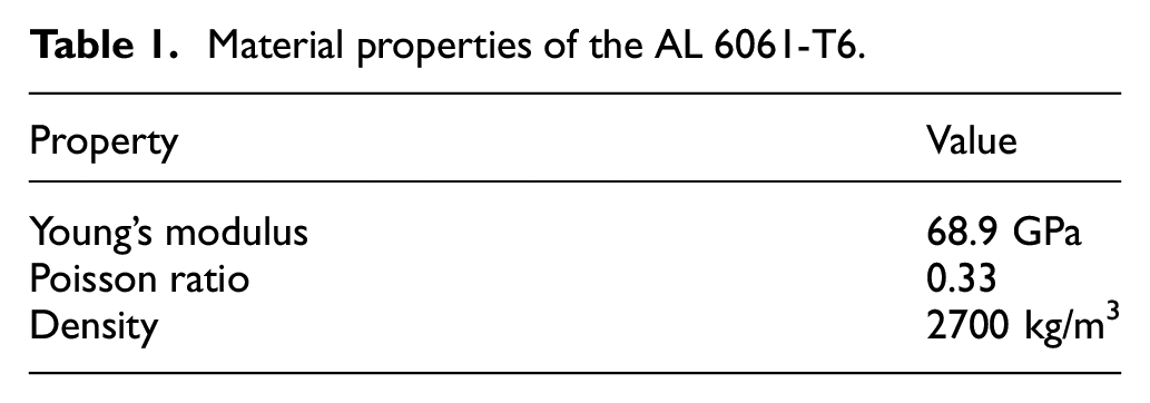
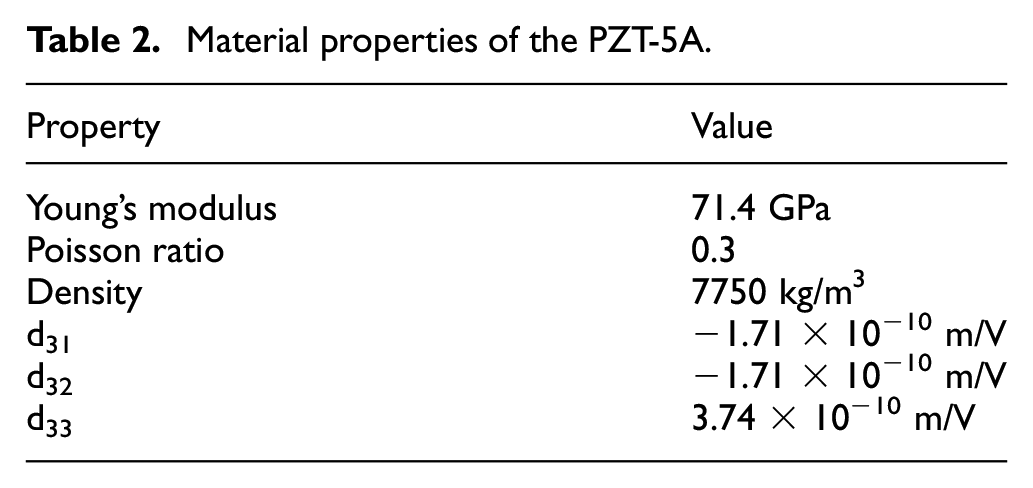
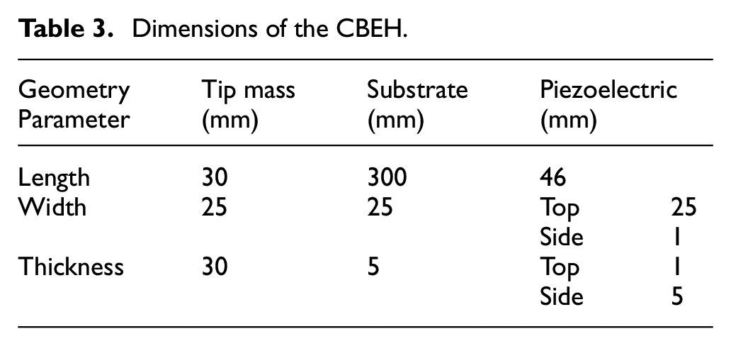
This study introduces three models: a CBEH and two FEHs. Among the latter, one model features symmetric cross-sections across all legs, whereas the other incorporates asymmetric cross-sections. Aluminum 6061-T6 was selected for all configurations due to its suitable properties, including lightweight, a high strength-to-weight ratio, corrosion resistance, and ease of fabrication (Kargar Gazkooh and Yousefi-Koma, 2024). These attributes collectively enhance the efficiency and durability of EHs. Both the substrate and the tip mass in these models employ this material. Additionally, Lead Zirconate Titanate (PZT-5A) piezoelectric transducers are utilized to generate electricity. As the volume of the piezoelectric material used for energy harvesting is of utmost importance, this study utilized the same volume of piezoelectric materials for all proposed EHs. A schematic of these models appears in Figure 1. The dimensions and specifications for these configurations are variable and detailed in subsequent tables: Table 1 lists the mechanical properties of the aluminum material, Table 2 presents the electromechanical properties of the piezoelectric transducers, Tables 3 to 5 outline the dimensions of the CBEH, symmetric-FEH, and asymmetric-FEH, respectively.
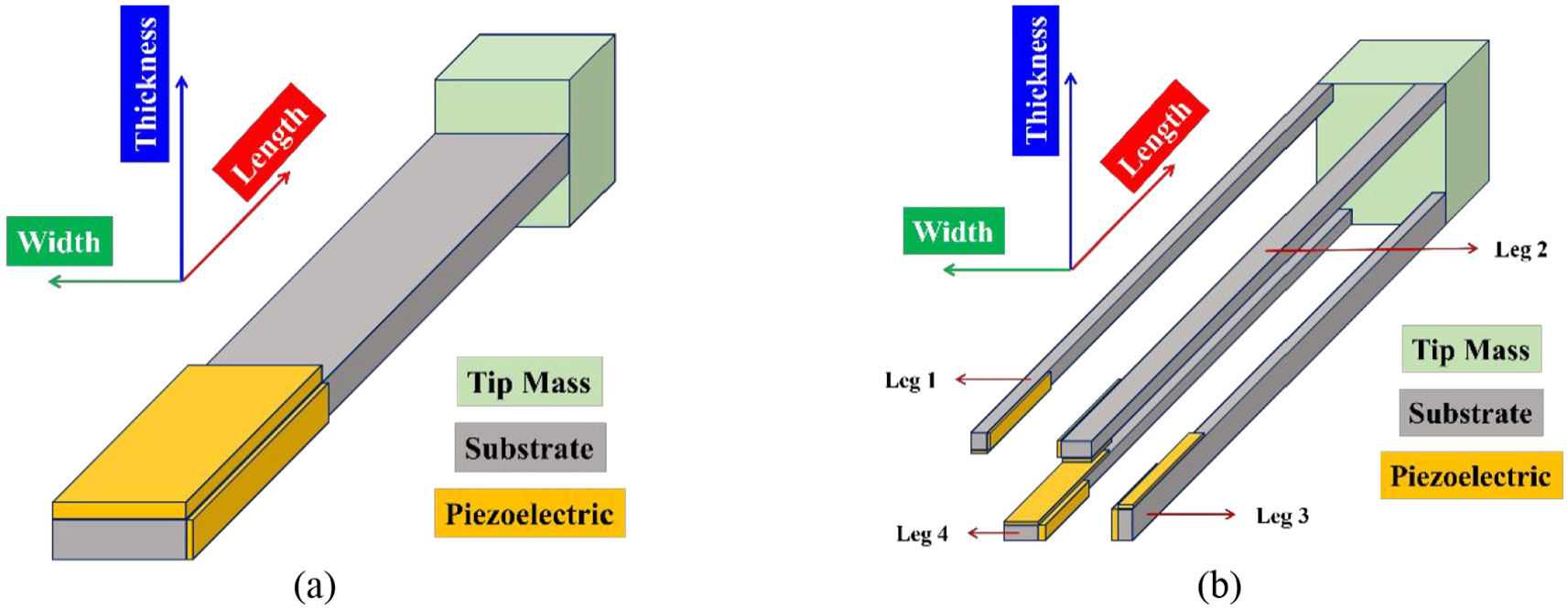
A schematic of (a) CBEH and (b) FEH configurations.
Material properties of the AL 6061-T6.
Material properties of the PZT-5A.
Dimensions of the CBEH.
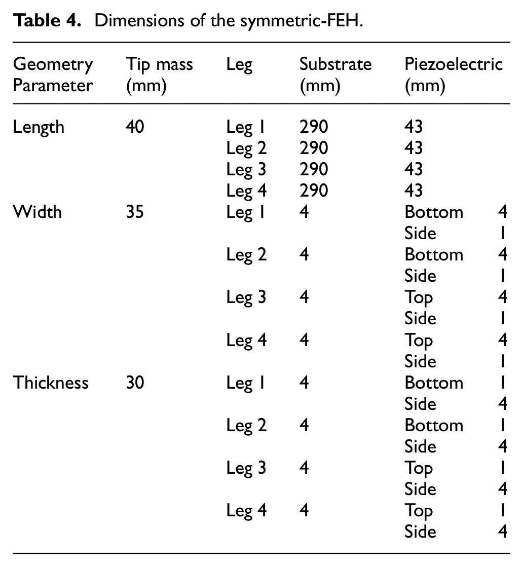
Dimensions of the symmetric-FEH.
Dimensions of the asymmetric-FEH.
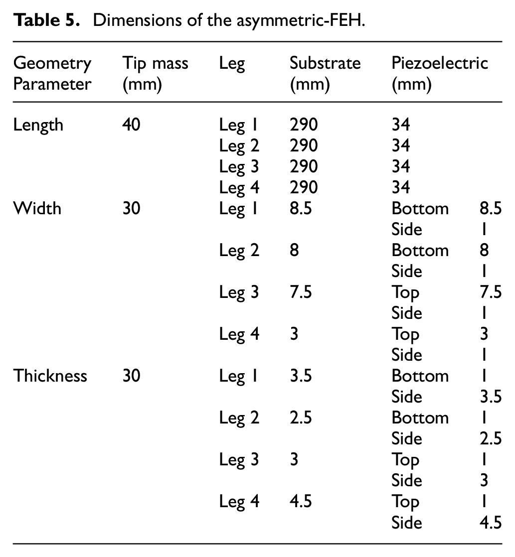
It is also worth mentioning that for the top piezoelectric layers, the length, width, and thickness directions correspond to the 1, 2, and 3 directions, respectively. However, for the side piezoelectric layers, the length, thickness, and width directions correspond to the 1, 2, and 3 directions as mentioned in Table 2, which lists the dielectric constants for the piezoelectric operation modes.
2.2. Finite element method
This research utilized the finite element software package COMSOL Multiphysics 5.5 to conduct numerical studies. This software facilitates the coupling of different physical domains, simplifying the investigation of their interdependencies in multiphysics problems. The analysis is divided into two principal studies: modal analysis and electromechanical analysis. The solid mechanics physics interface was chosen in the modal analysis, and an eigenfrequency study was incorporated. Following this, the components outlined in Tables 3 to 5 were modeled. As mentioned in the previous subsection, AL 6061-T6 and PZT-5A were selected from the material library and applied to the appropriate geometry sections. The analysis culminated in identifying the natural frequencies of the systems below 1000 Hz and their corresponding mode shapes.
In the electromechanical analysis, the piezoelectricity and electrical circuit physics interfaces were employed, supplemented by a frequency domain study to delineate the frequency response of the proposed VPEHs. The substrate and tip mass geometries were specified as a linear elastic material, whereas the piezoelectric layer was categorized under the piezoelectric material subsection. It is important to note that piezoelectric materials primarily respond to excitations applied perpendicular to their surface. Consequently, piezoelectric materials with varying orientations were designated for different piezoelectric layers. To accommodate these orientations, various base vector systems were defined within the definitions module and subsequently assigned to the corresponding piezoelectric layers. Harmonic base excitations were modeled by applying two body loads along the z and y directions to the entire geometry. Furthermore, an isotropic damping loss factor of 5% was applied to substrate, piezoelectric layers, and tip mass (Muthalif and Nordin, 2015; Pradeesh and Udhayakumar, 2019). The electrostatic module facilitated the alignment of nodes with the electrodes, attaching the bottom surface of the piezoelectric layer (in contact with the substrate) to a ground electrode and the top surface to a terminal electrode. The terminal type was selected as a circuit type linked to an electrical load resistor within the electrical circuit module to assess the EH’s electrical response. Additionally, resistors with various values were integrated into the systems, which will be discussed in the following subsections.
To model the clamped boundary conditions, the left boundaries of substrates (at x = 0) receive fixed constraints. As the final step, the design undergoes meshing to discretize the geometry for the finite element analysis. A mesh convergence study was initially conducted to select appropriately the type and number of mesh elements. Accordingly, the analysis utilized 15,417, 15,284, and 17,596 tetrahedra elements for the CBEH, symmetric-FEH, and asymmetric-FEH, respectively. Finally, simulations occurred in the frequency domain from 10 to 1000 Hz. Figure 2 displays the CBEH, the developed FEHs, and their associated cross-sections modeled in COMSOL.
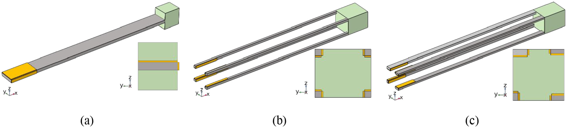
Schematic of (a) CBEH, (b) symmetric-FEH, and (c) asymmetric-FEH, each with their associated cross-sectional views, designed in COMSOL.
2.3. Numerical results
As indicated in Section 1, the objective of the present study is to develop a multimodal and multidirectional FEH that addresses current limitations in state-of-the-art VPEHs and demonstrates better performance compared to the CBEH. Consequently, the first step involved conducting an eigenfrequency analysis to compare the efficiency of the developed FEHs with that of the CBEH. Subsequently, the second step entailed an electromechanical analysis to investigate the amount of energy harvested using the VPEHs under study.
2.3.1. Modal analysis
Figure 3 demonstrates the first bending natural modes about the z and y axes and the first torsional natural modes, along with their natural frequencies, to investigate the multidirectionality of the VPEHs under study. Moreover, the contour depicted in Figure 3 represents the schematic relative displacement of the proposed harvesters.
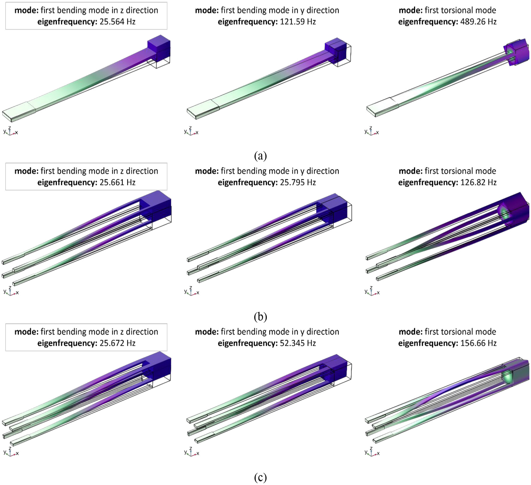
First bending and torsional natural modes: (a) CBEH, (b) symmetric-FEH, and (c) asymmetric-FEH.
For a more reliable comparison, the design of the FEHs, as previously discussed and illustrated in Figure 3, matches the first bending natural frequencies around the z-axis closely with those of the CBEH. This precise alignment ensures effective resonance with environmental vibrations. The CBEH resonates at 25.564 Hz, the symmetric-FEH at 25.661 Hz, and the asymmetric-FEH at 25.672 Hz. This configuration optimizes the performance of the VPEHs under similar operational conditions. Moreover, the symmetric-FEH maintains a low frequency of 25 Hz around both the z and y axes. This configuration broadens its operational bandwidth and enhances its capability to harvest energy from ambient vibrations in multiple directions. This feature is beneficial in environments where vibrational energy spans multiple planes. Additionally, the asymmetric-FEH demonstrates an advantage with its first bending frequency around the y-axis recorded at 52.345 Hz, significantly lower than that of the CBEH.
To understand the distribution and density of natural frequencies within the CBEH and the proposed FEHs, this study introduces the MMI as a quantitative metric, defined by equation (1). This index provides insights into the structure’s potential to capture energy from various vibrational sources across different frequencies.
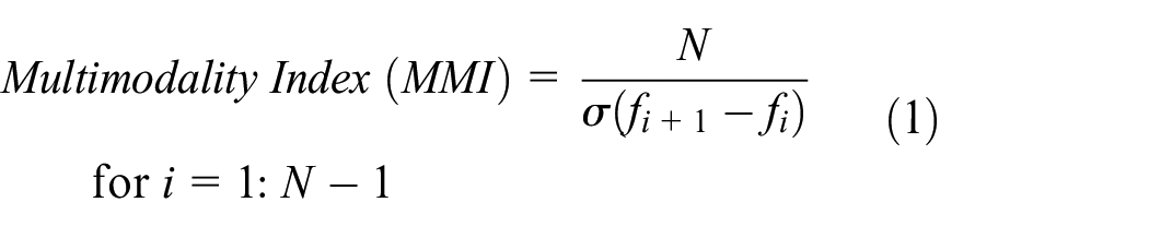
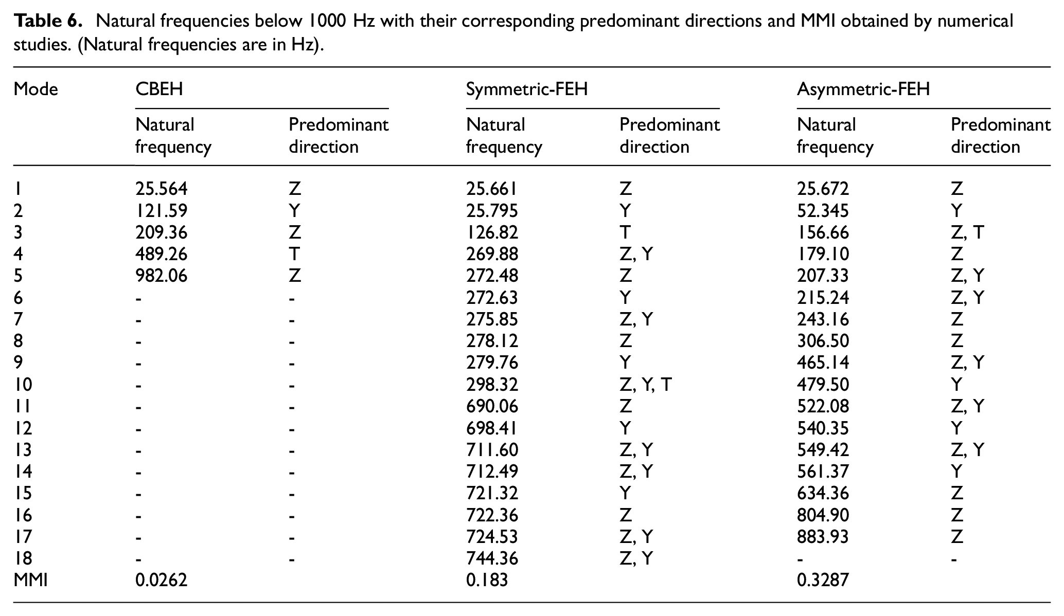
where N represents the number of natural frequencies below 1000 Hz and σ (f i+1 −f i ) denotes the standard deviation of the differences between consecutive natural frequencies across all i=N – 1. This formulation captures two fundamental aspects of modal behavior: the total count of natural frequencies, which reflects the system’s responsiveness across a given frequency range, and the uniformity in the spacing of these frequencies, which affects how the structure can simultaneously engage multiple vibrational modes. Table 6 summarizes the natural modes with their predominant displacement directions and the MMI of the proposed VPEHs, with the mode shapes of the first three modes of symmetric-FEH and asymmetric-FEH and the first, second, and fourth modes of the CBEH are illustrated in Figure 3. It is worth mentioning that the directions of each mode are determined based on which displacement directions are predominant. Moreover, the z and y directions are the same as those depicted in Figure 3, and “T” represents the torsional mode. Additionally, Figure 4 illustrates the natural frequency distribution under 1000 Hz for the VPEHs under study.
Natural frequencies below 1000 Hz with their corresponding predominant directions and MMI obtained by numerical studies. (Natural frequencies are in Hz).
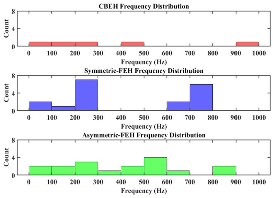
Natural frequency distribution for CBEH, symmetric-FEH, and asymmetric-FEH.
From the results of Table 6 regarding the predominant displacement directions, it is clearly demonstrated that the proposed FEHs achieve broadband performance in the z and y directions. Additionally, Table 6 reveals significant differences in the MMI values for each configuration, highlighting the varying capabilities of the structures as efficient multimodal EHs. The CBEH, with a lower MMI of 0.0262, exhibits a large standard deviation in frequency differences, indicating a less uniform distribution of natural frequencies and a potential limitation in responding to a broad range of frequencies. In contrast, the asymmetric-FEH, with the highest MMI of 0.3287, shows the smallest standard deviation, indicating a highly uniform distribution of natural frequencies. This uniformity enables it to effectively engage multiple vibrational modes, making it particularly adept at harvesting energy from diverse environmental vibrations.
The symmetric-FEH, with an MMI of 0.183, presents a different scenario where the modal frequencies are more clustered than the asymmetric-FEH, as depicted in Figure 4. This clustering, indicated by a standard deviation of 98.37 Hz, suggests that while the symmetric-FEH can engage multiple modes, the proximity of its natural frequencies may limit the range of vibrational energy it can effectively harness. Consequently, this could lead to suboptimal energy harvesting performance in environments where vibrational frequency inputs do not align closely with these clustered frequencies. Therefore, despite its higher MMI compared to the CBEH, the effectiveness of the symmetric-FEH is constrained by its less evenly spread natural frequencies. The asymmetric-FEH, on the other hand, demonstrates superior performance due to its high MMI and uniform distribution of natural frequencies below 1000 Hz. This uniformity implies that the asymmetric-FEH can effectively engage multiple vibrational modes simultaneously, enhancing its ability to convert mechanical vibrations into electrical energy across a broad spectrum of frequencies. Additionally, the low standard deviation of frequency differences (51.71 Hz) suggests that it can consistently respond to a wide range of vibrational inputs without being limited to narrow frequency bands, making it highly suitable for practical applications where the conditions of vibrational energy are not static or well-defined.
2.3.2. Strain analysis
Due to the fact that piezoelectric materials produce voltage in response to the strain generated in them (known as direct piezoelectric effect; Erturk and Inman, 2011), a significant criterion for a piezoelectric EH to achieve high efficiency is to have areas with high strains. In order to investigate this property, the dynamic strain of the proposed EHs was calculated and is represented in Figure 5, when subjected to a base excitation with an amplitude of 0.1g, where g is the acceleration of gravity (g = 9.81 m/s2).
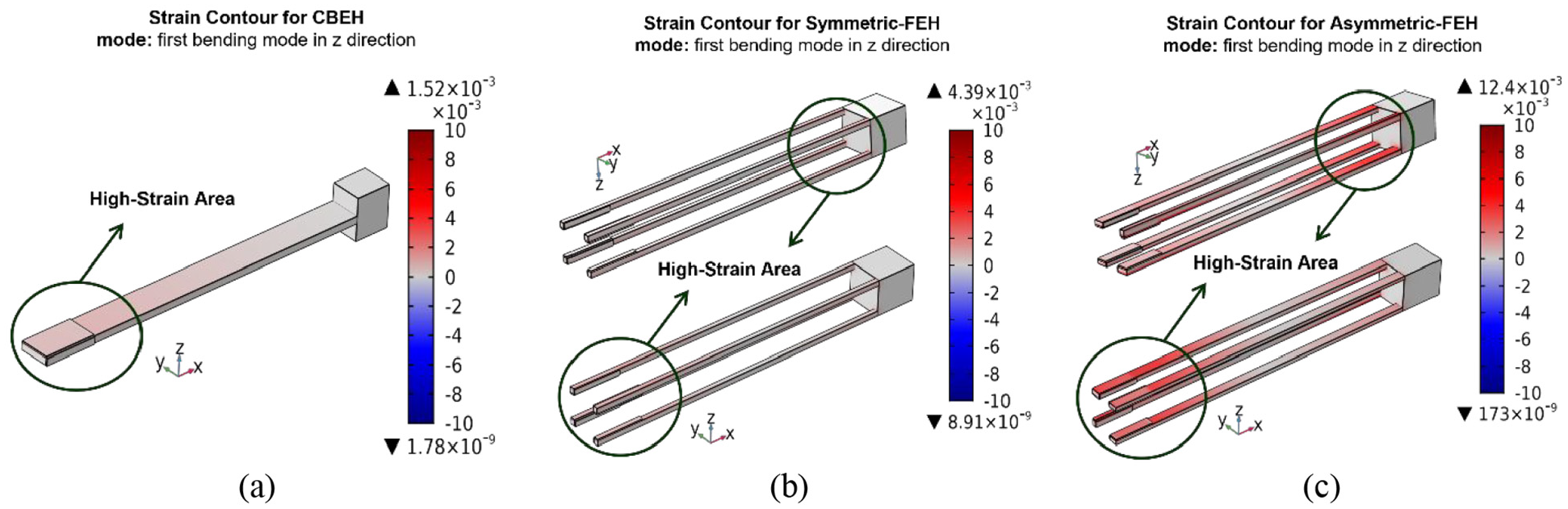
Strain contour for the proposed (a) CBEH, (b) symmetric-FEH, and (c) asymmetric-FEH.
As is evident from Figure 5, the areas with high strain amounts in FEHs, weather symmetric or asymmetric, are greater than those of the corresponding CBEH. In other words, each leg of the FEHs acts like a clamped-clamped beam with high strain areas at both ends. Additionally, the strain level in the asymmetric-FEH (12.4 × 10⁻³) is significantly higher than in the symmetric-FEH (4.39 × 10⁻³) and CBEH (1.52 × 10⁻³). This study demonstrates that the proposed FEHs address the limitation of low strain level and limited high-strain areas observed in CBEHs. Moreover, the asymmetric-FEH excels in generating higher strain levels within the structure, thereby enhancing its capacity to produce more voltage by piezoelectric materials. Therefore, using modal analysis, the MMI results, and strain analysis, it is clear that FEHs overcome all the limitations of the CBEHs. In conclusion, when comparing the two FEHs, the asymmetric-FEH offers distinct advantages over the symmetric-FEH in terms of multidirectional and multimodal energy harvesting capabilities. Its superior MMI, more uniform frequency distribution, and higher strain levels, and more extensive high-strain areas enable it to perform optimally across various vibrational scenarios, thus outperforming the symmetric-FEH in achieving greater energy harvesting efficiency and adaptability. This decisively positions the asymmetric-FEH as the preferable choice for developing efficient and versatile VPEH. Henceforth, this study will consider asymmetric-FEH from the proposed FEHs to investigate its electromechanical performance against CBEH.
2.3.3. Electromechanical analysis
As discussed earlier, electromechanical analysis was conducted using COMSOL Multiphysics 5.5 to investigate the amount of power that can be harvested from the proposed VPEHs. Since the amount of electrical power scavenged depends highly on the volume of the utilized piezoelectric material, nearly the same volume of piezoelectric material was used for both the CBEH and the asymmetric-FEH. The dimensions used in this study are summarized in Table 3 for CBEH and in Table 5 for asymmetric-FEH. As illustrated in Figure 1, the piezoelectric materials were bonded to the beginning of the legs from the cantilevered end. The configurations were designed so that the piezoelectric materials cover the width or thickness of the legs, depending on where they were bonded.
Determining the optimal load resistance is a crucial initial step in maximizing device performance when subjected to ambient vibrations. To assess the performance of VPEHs under varying operational conditions, this study presents output voltage and power against load resistance diagrams across 26 different load resistances ranging from 1 to 105 kΩ. Moreover, the first three natural modes of the VPEHs were considered to provide detailed information about the specific characteristics of each VPEH. By examining these modes, the study captures the dynamic response of the VPEHs across a frequency range of 10–1000 Hz. This approach provides deeper insight into the frequency-dependent performance of the VPEHs, revealing how their efficiency can vary not only with changes in load resistance but also with different vibrational inputs. In this study, the output power can be calculated using equation (2):
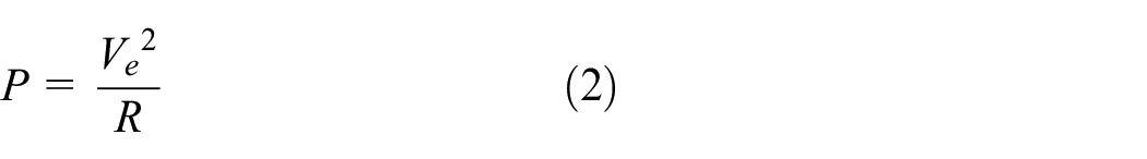
where P represents the power output, R denotes the load resistance, and V e is the effective voltage. The effective voltage V e can be obtained by equation (3), which accounts for the multidirectional nature of the mechanical excitations on the piezoelectric material.
where V z and V y are the voltages generated along z and y axes, respectively. Figures 6 and 7 represent the magnitude of the output voltage and power for CBEH and asymmetric-FEH, respectively, when subjected to a harmonic base excitation with an amplitude of 0.1g, where g is the acceleration of gravity (g = 9.81 m/s2).
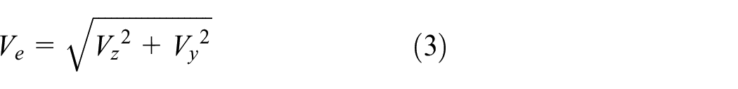
(a) The output voltage and (b) the output power against different load resistances for the first three natural modes of the CBEH.
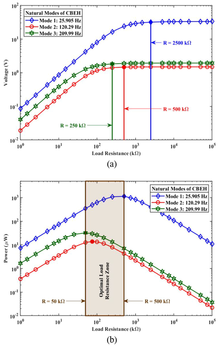
(a) The output voltage and (b) the output power against different load resistances for the first three natural modes of the asymmetric-FEH.
Figures 6(a) and 7(a) show that across all three modes, the voltage increases with load resistance up to a specific threshold (the saturation load resistance) for each mode, beyond which the voltage remains constant. The saturation points vary, with the third mode reaching saturation at the lowest resistance (250 kΩ for both VPEHs), followed by the second mode (500 kΩ for the CBEH and 750 kΩ for the asymmetric-FEH), and the first mode (2500 kΩ for the CBEH and 5000 kΩ for the asymmetric-FEH). This suggests that higher frequency modes achieve voltage saturation at lower resistances compared to lower frequency modes. The maximum output voltage for the CBEH is 33.12, 1.485, and 1.927 V for its first three modes. In comparison, the asymmetric-FEH achieves maximum output voltages of 57.75, 14.14, and 0.1678 V for its first three modes.
These figures also highlight other important points. The first and third modes of the CBEH, primarily involving z-direction deflections, exhibit higher strain magnitudes, maximizing both tensile and compressive strains along the beam’s length. This increased strain enhances the conversion efficiency of mechanical energy into electrical energy using piezoelectric material. The second mode, characterized by y-direction deformations, involves lower strain levels, resulting in less effective energy conversion. Conversely, the first and second modes of the asymmetric-FEH involve z-direction and y-direction deflections, respectively. These modes exhibit high strain in both directions due to their multidirectional nature, thus converting mechanical strain to electrical power more efficiently than the third mode, which is a torsional mode. In the asymmetric-FEH, most of the torsional modes coexist with bending modes, allowing energy scavenging from torsional modes when excited in the z or y directions.
Figures 6(b) and 7(b) show that the output power initially increases with load resistance, peaking at various resistances for each VPEH. Beyond this peak, the output power declines steadily, suggesting an optimal resistance range where the output power is maximized. The optimal load resistance zone spans approximately 50–500 kΩ for the CBEH and up to 250 kΩ for the asymmetric-FEH. This zone is marked by a shaded region on the graph, where all three modes exhibit their peak output power. This indicates that this resistance range is critical for optimizing power performance across all modes. Although the load resistance that maximizes the first natural mode’s power could be considered optimal, in environments where the first mode is not excited, the second or third mode can still generate energy. Therefore, choosing a load resistance that provides good performance across all modes is crucial. Hence, for this study, 150 kΩ is chosen as the optimal load resistance for both VPEHs.
This study applies base excitation to both VPEHs in the z- and y-directions. Figure 8 shows the optimal output voltage of the VPEHs at an optimal load resistance of 150 kΩ. As it is obvious from Figure 8 and mentioned earlier, the piezoelectric layers mostly respond to excitations applied perpendicular to their surface. Figure 8(a) indicates that the CBEH is not ideal for harvesting multidirectional energies in complex vibrational environments because its surface, mainly oriented in the z-direction, limits its responsiveness. Additionally, it has only four bending modes below 1000 Hz, preventing it from being a multimodal VPEH. On the other hand, Figure 8(b) shows that the asymmetric-FEH can effectively harvest energy from different directions across a broad frequency spectrum.
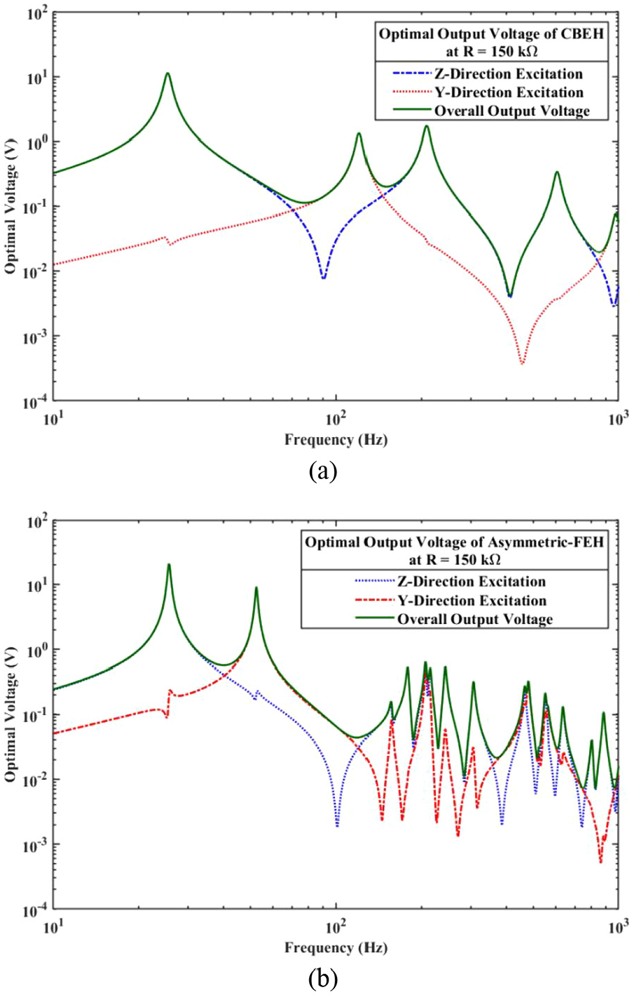
The optimal voltage frequency-response of (a) the CBEH and (b) the asymmetric-FEH.
Since the output voltage is not the only important metric, Figure 9 presents the overall optimal output power of both VPEHs at an optimal load resistance of 150 kΩ. This figure demonstrates that the proposed asymmetric-FEH outperforms the CBEH. For instance, within the frequency range of 10–200 Hz, the asymmetric-FEH can harvest an average power of 18.96 µW, surpassing the CBEH, which can harvest an average power of 10.47 µW within the same frequency range. This comparison highlights the better performance of the asymmetric-FEH in terms of optimal output power.
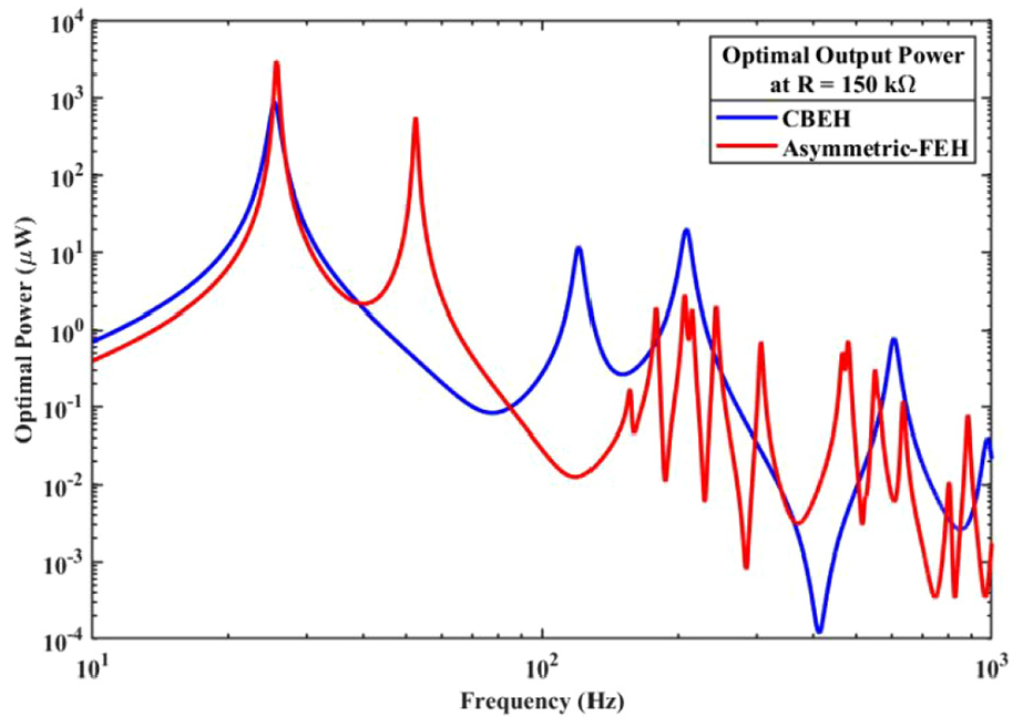
The optimal power frequency response of the CBEH and asymmetric-FEH.
Analyzing both short and open circuit resonance frequencies (f S.C. and f O.C. ) is essential for optimizing device performance and power output. Open circuit conditions help determine the resonance frequency of the harvester with no load (high impedance), providing insights into the maximum voltage output potential. Conversely, short circuit analysis reveals the resonance under zero impedance, crucial for understanding maximum current output. These parameters are vital for tuning the matching circuit elements, like resistors and inductors, to achieve maximum power transfer efficiency. Additionally, discrepancies between these frequencies can inform decisions on device design adjustments and material selections to better align the harvester with environmental vibrational frequencies, thus enhancing overall efficiency and effectiveness.
As is known and mentioned above, the short circuit condition is expected for low values of load resistance (R → 0), while the VPEH expected to shift toward the open circuit condition at large load resistance values (R →∞). The two crucial excitation frequencies are the f S.C. and f O.C. . To calculate these frequencies, the output power frequency-response was determined for various load resistances, ranging from 1–1×10⁶ kΩ, as depicted in Figure 10. Since the first mode of the proposed VPEHs has the most significant impact on the amount of harvested energy, only this mode was considered for determining f S.C. and f O.C. of these VPEHs. As load resistance increases, the resonance frequency of the proposed VPEHs transitions from the f S.C. to f O.C. . Notably, since the first mode was used to determine the f S.C. and f O.C. , load resistances of 500 and 250 kΩ (the saturation load resistance for each VPEH at their first mode) were selected for the CBEH and asymmetric-FEH, respectively.
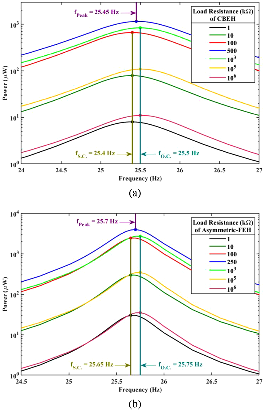
Output power frequency-response for different load resistances for (a) CBEH and (b) asymmetric-FEH.
As illustrated in Figure 10, the output power increases with rising load resistance until it reaches its maximum value for different VPEHs, after which it decreases with further increases in load resistance. Initially, the output power rises with increasing load resistance at f S.C. ; then, it is maximized at f Peak (a frequency between f S.C. and f O.C. ). Beyond this maximum value, the output power declines toward f O.C. as the load resistance continues to rise. This frequency shift occurs due to the interaction between the mechanical and electrical properties of the system. Lower load resistances introduce higher electrical damping, which lowers the system’s resonant frequency. In contrast, higher resistances reduce this damping effect, allowing the system to resonate at a higher frequency. This phenomenon highlights the importance of selecting the appropriate load resistance to achieve optimal resonance and output power based on the specific application requirements. Finally, considering all the results presented in this section, f O.C. , f S.C. , the output peak power, the corresponding excitation frequency, and the power density of the proposed VPEHs are extracted and listed in Table 7.
Dynamic and electric outputs of the proposed VPEHs.
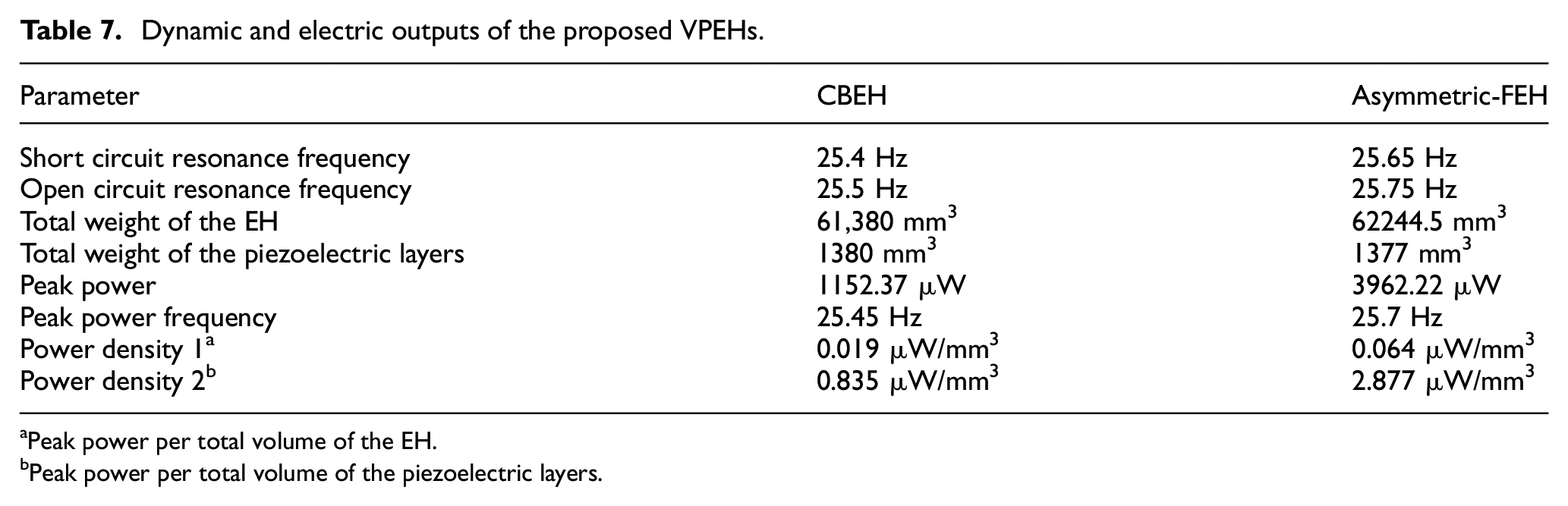
Peak power per total volume of the EH.
Peak power per total volume of the piezoelectric layers.
3. Experimental studies, results, and discussion
Experimental analysis following numerical studies is essential to validate the accuracy and reliability of the VPEHs. Researchers can identify discrepancies and refine the models for improved accuracy by comparing numerical simulation results with experimental data. Experimental analysis also provides additional insights, enhancing understanding of system behavior under real-world conditions. Therefore, conducting experimental analysis after numerical simulations is crucial for validating and improving the numerical models. This study conducted experimental investigations to measure the performance of the proposed VPEHs under various vibration conditions. The numerical model used for simulations was meticulously aligned with the excitations, materials, and geometry of the experimental setup to ensure consistency and reliability in the comparative analysis.
3.1. Experimental setup
Figure 11 illustrates the experimental test setup designed to conduct an electromechanical analysis and determine the output power of the CBEH and asymmetric-FEH. The substrate and tip mass of the proposed VPEHs were created using AL6061-T6 material. PZT-5A piezoelectric materials were bonded to substrates using UHU PLUS ENDFEST 2-KEPOXIDKLEBER glue. The piezoelectric layers were connected in series to a breadboard. Then, vibrational energy is transformed into electricity using a full-bridge rectifier circuit. A W10M bridge rectifier with a maximum root mean square voltage of 700 V and a maximum direct current blocking voltage of 1000 V was used in this study. The resistor used in this study was a carbon film axial leaded through-hole type with a power rating of 0.25 W, and variable load resistances ranging from 1– 1×10⁵ kΩ with a 5% tolerance. The circuit output on the breadboard was connected via a Bayonet Neill-Concelman cable to a Spider 80x Crystal data acquisition system, which has eight input channels and a sampling frequency of 102.4 kHz per channel, to record the data. The proposed VPEHs were fixed on the head of a 2.5 kN electromechanical shaker with designed fixtures. All recorded data were stored in the Engineering Data Management software for further analysis.
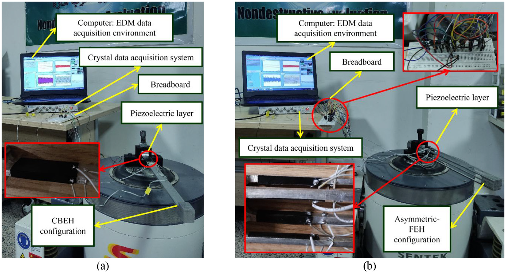
Experimental setup used for electromechanical analysis of (a) the CBEH and (b) the asymmetric-FEH configurations.
3.2. Experimental results
This section compares the voltage and power generated at different load resistances and frequencies for the CBEH and asymmetric-FEH. Figure 12 presents the output voltage and power against various load resistances for the CBEH, while Figure 13 does the same for the asymmetric-FEH. In these figures, the blue line and symbols indicate the first natural mode, the red line and symbols indicate the second natural mode, and the green line and symbols indicate the third natural mode of the proposed CBEH and asymmetric-FEH. Notably, the lines represent simulation results, while the symbols represent experimental results.
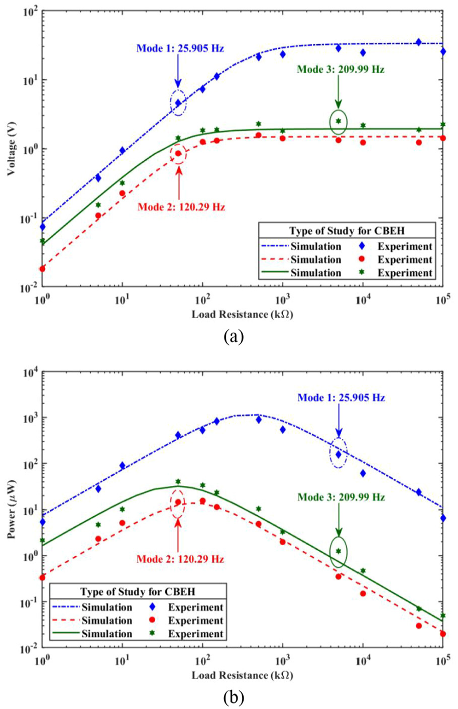
(a) The output voltage and (b) the output power against different load resistances for the first three natural modes of the CBEH..
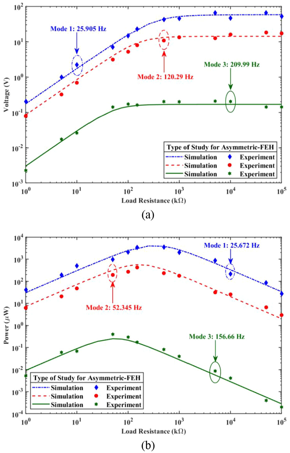
(a) The output voltage and (b) the output power against different load resistances for the first three natural modes of the asymmetric-FEH..
Additionally, Figure 14 demonstrates the frequency response of the output voltage for both the CBEH and asymmetric-FEH, while Figure 15 shows the frequency response of the output power. In Figure 14, red lines represent the results for the CBEH, and blue lines represent the results for the asymmetric-FEH. The alignment between these results verifies the experimental output voltage measurements. On the other hand, in Figure 15, blue dashed lines indicate simulation results, and solid red lines represent experimental results. As shown in Figure 15(a) and the zoomed section of Figure 15(b), each diagram reveals one mode detected in the experiments but not in the simulations. These modes are related to the torsional modes of these VPEHs. The detection of an additional mode in the experimental frequency response, absent in the simulations, can be explained by the nature of the excitations used in each case. In the simulations, the system was excited purely in the z and y directions, targeting bending modes and not capturing the pure torsional mode. Conversely, the experimental setup utilized a shaker, likely introducing excitations beyond the z and y directions. This broader range of excitations in the experiment included torsional components, allowing the detection of the torsional mode that the simulations did not predict. It is worth mentioning that most of the torsional modes of the asymmetric-FEH were detected in the simulations because the torsional modes of this VPEH were mixed with bending modes, that is, they were not purely torsional modes. However, the torsional mode detected for this VPEH in experiments was purely torsional, which the simulations did not account for.
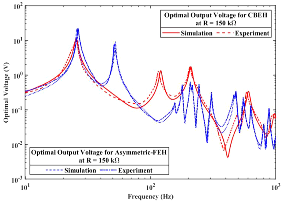
Optimal output voltage frequency-response of the CBEH and asymmetric-FEH.
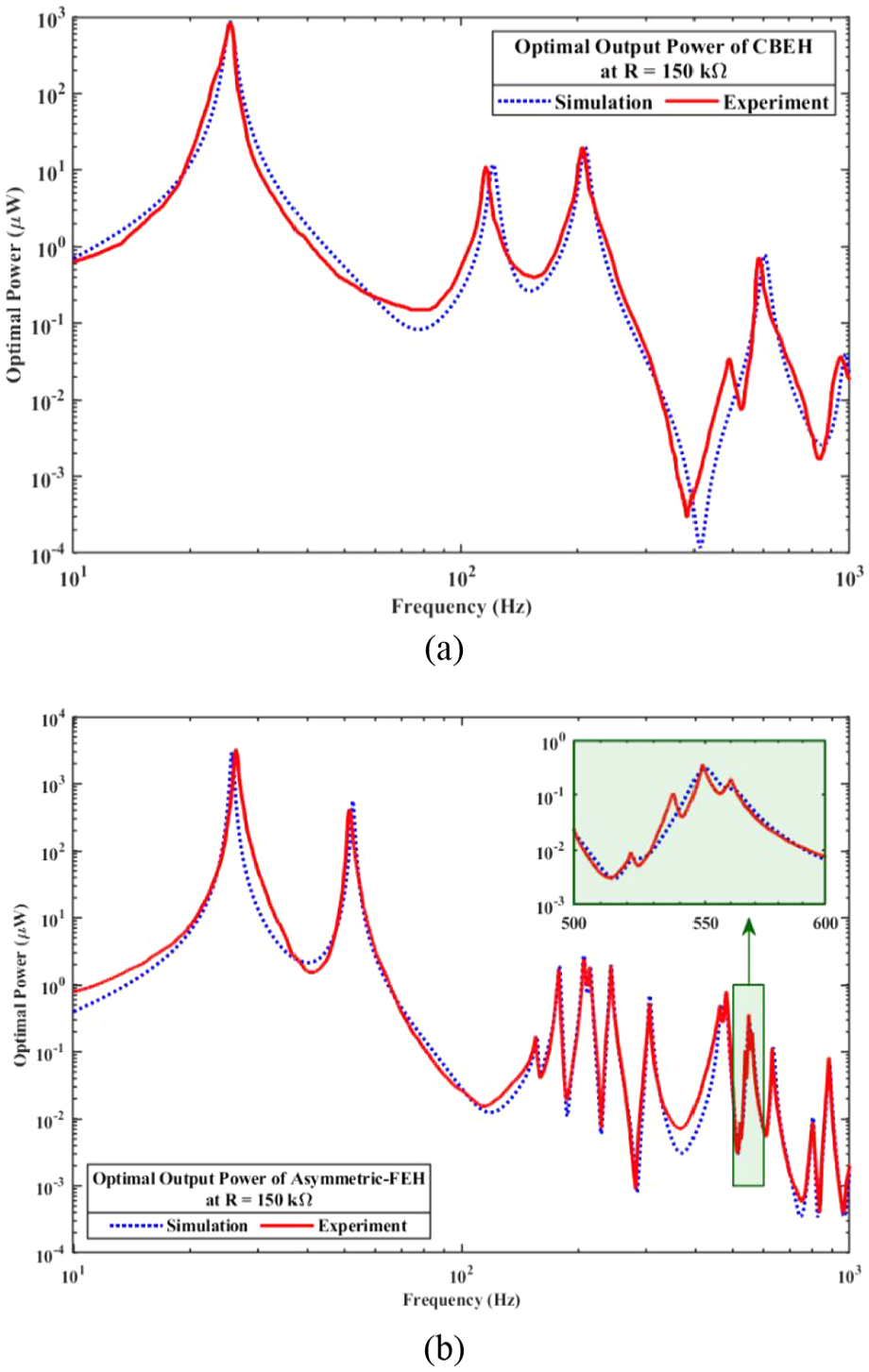
Optimal output power frequency-response of the (a) CBEH and (b) asymmetric-FEH.
The experimental results show minor variations compared to the simulations regarding natural frequencies and the amount of harvested voltage and power, as indicated in Figures 14 and 15. Several key factors contribute to these differences. Firstly, material properties such as stiffness, density, and damping often vary in practical applications due to manufacturing tolerances and inconsistencies, which can shift natural frequencies and affect energy harvesting efficiency. Additionally, despite efforts to establish the most optimal connections, the perfect piezoelectric connections assumed in the finite element studies may have yet to be replicated precisely in the experimental setup. Furthermore, electrical losses from wiring resistance and inefficiencies in power conditioning circuitry can also reduce the harvested power in experiments. Finally, measurement errors such as signal noise can contribute to differences in observed natural frequencies and harvested power. Addressing these factors in both simulations and experiments can enhance the accuracy and reliability of energy harvesting system predictions. Despite these variations, a strong agreement can be observed between the results obtained from the experimental studies and simulations, indicating their consistency and validity. Additionally, to further demonstrate the effectiveness of the proposed asymmetric-FEH compared to other recent multidirectional and multimodal VPEHs, a performance comparison is presented in Table 8.
Performance comparison of the proposed asymmetric-FEH with recently published multimodal and multidirectional VPEHs.
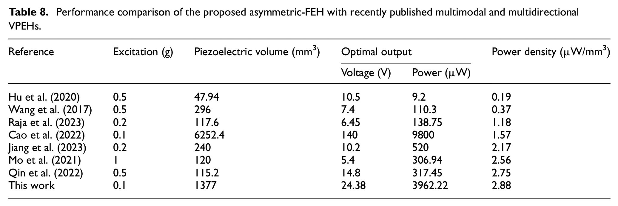
This table focuses on piezoelectric volume, optimal output, and the corresponding power density (calculated by dividing the maximum power output by the volume of the piezoelectric layers) under specified excitations. It is important to note that excitation acceleration is a crucial factor affecting power output, where power output increases with increasing excitation acceleration (Xing et al., 2023). The excitation acceleration in our study is 0.1g, which is lower than that of other references summarized in Table 8. Despite this lower excitation, our proposed asymmetric-FEH can harvest more energy than other recently reported harvesters, making it more suitable for capturing ambient vibrations from daily human activities and passing vehicles with low vibrational sources. Moreover, Cao et al. (2022) also used 0.1g excitation in their study. They utilized a larger volume of piezoelectric layers and produced more voltage and power. However, their design falls short in terms of generated power per unit volume of piezoelectric layer compared to this study.
Additionally, although the size of the piezoelectric layers used in our study is greater than in most of the studies summarized in Table 8, the goal of this study was not to minimize the design. Instead, the aim was to create a harvester that addresses the existing drawbacks of CBEHs while simultaneously offering better performance than current harvesters. Furthermore, the proposed asymmetric-FEH is intended for installation in bridges and railways for structural health monitoring and for powering wireless sensor nodes. Therefore, it must have a robust design to withstand harsh environments with dynamic loads. Finally, the data from Table 8 clearly demonstrate that our proposed asymmetric-FEH outperforms recent multimodal and multidirectional VPEHs in terms of power density and sensitivity to weaker vibrational inputs.
4. Summary and conclusions
This research developed a multimodal and multidirectional asymmetric-FEH, which enhanced the efficiency of VPEH designs. The study investigated the efficacy of CBEH and FEHs using three-dimensional finite element simulations and experimental studies. Moreover, all VPEHs were designed to have the same length, closely matched first natural frequencies, and nearly the same weight to conduct a reliable comparison.
Three different VPEHs were proposed: a CBEH, a symmetric-FEH, and an asymmetric-FEH. Notably, MMI was introduced and utilized to determine the multimodality of the proposed VPEHs. Both the symmetric-FEH and asymmetric-FEH were capable of harvesting energy from vibrations in multiple directions. However, the symmetric-FEH had clustered natural frequencies, limiting its ability to scavenge energy from a wide frequency range. In contrast, the asymmetric-FEH, with the highest MMI (0.3287), exhibited natural frequencies uniformly distributed within the considered range. Therefore, the FEHs, specifically the asymmetric-FEH, addressed critical challenges of CBEHs, such as unidirectionality, limited bandwidth, and low strain levels.
The study conducted numerous simulations with different load resistances for excitations applied to VPEHs in various directions to determine the optimal load resistance for each configuration. It was shown that increasing the load resistance led to an increase in the harvested voltage for all modes until saturation load resistance was reached, at which point the output voltage saturated. Beyond this point, the output voltage remained constant despite further increases in load resistance. Consequently, the saturation load resistance for each mode was determined. Additionally, increasing the load resistance initially increased the harvested power, but beyond the optimal load resistance value for each mode, the harvested power decreased with further increases in the load resistance.
By extracting the optimal load resistance for the whole structure, further simulations were conducted to determine the optimal harvested voltage and power for each VPEH. The results showed that the developed asymmetric-FEH outperforms the CBEH in terms of optimal output voltage and power. Moreover, the output power frequency-response was determined for various load resistances, focusing on the first mode, as it has the most significant impact on harvested power. The results showed that as load resistance increased, the output peak power also increased at f S.C. . At the saturation load resistance for each EH, the output peak power reached its maximum between f S.C. and f O.C. . However, further increases in the load resistance resulted in a decrease in output peak power at f O.C. .
These investigations demonstrate that the asymmetric-FEH efficiently overcomes the limitations of CBEHs. Specifically, the power density of the CBEH per volume of the piezoelectric layers was 0.835 µW/mm3, while the power density of the asymmetric-FEH per unit volume of the piezoelectric layers was 2.877 µW/mm3, indicating that the asymmetric-FEH can harvest 3.44 times more power than the proposed CBEH, considering their first natural modes. Additionally, the first torsional natural frequency of the asymmetric-FEH is much lower than that of the CBEH, highlighting the inadequacy of CBEHs to harvest energy from torsional modes within the usual frequency range available in most environments. Furthermore, the internal volume of the developed asymmetric-FEH and the surfaces of the tip mass can be utilized for electronic circuitry, thereby reducing the overall volume of the VPEH.
The present investigation focused on introducing a multimodal and multidirectional frame-like topology that can effectively overcome the limitations of CBEHs, improve the efficiency and broaden the frequency bandwidth of the existing state-of-the-art designs. Additionally, the internal volume of the developed asymmetric-FEH can accommodate electrical components, resulting in a more compact design. Future studies may explore other frame-like configurations and leg placement optimization to evaluate their efficacy. Additionally, incorporating electromagnetic transducers to create a hybrid VPEH is a promising avenue for further research.
Footnotes
Declaration of conflicting interests
The authors declared no potential conflicts of interest with respect to the research, authorship, and/or publication of this article.
Funding
The author(s) received no financial support for the research, authorship, and/or publication of this article.
Data availability
The datasets generated during and/or analyzed during the current study are not publicly available due to ongoing investigations for further research purposes, but are available from the corresponding author on reasonable request.