
Abstract
The sustainable powering of sensor networks remains a significant challenge due to the inherent limitations of conventional battery technologies. This study proposes a vibration-magnetic dual-mode energy harvester based on diamagnetic levitation. The device integrates an independent-layer triboelectric nanogenerator (TENG) with a diamagnetically levitated structure, enabling hybrid energy harvesting from ambient mechanical vibrations and alternating magnetic fields. At a vibration acceleration of 1.34g and a frequency of 58 Hz, the harvester achieves a peak voltage of 5.3 V. Under dual-mode excitation with frequency and phase-matched mechanical (0.89 g) and magnetic (22 mT) inputs, the output voltage is enhanced by 31.7% compared to vibration-only excitation. Moreover, the phase difference between the two excitation sources significantly influences the output performance under coupled conditions. Finally, application experiments demonstrate that the device can detect the magnetic fields generated by high-power household appliances. This work demonstrates a viable energy harvesting strategy that utilizes environmental mechanical and magnetic energy sources, offering improved energy conversion efficiency and system reliability for self-powered sensing applications.
Introduction
With the rapid advancement of the Internet of Things (IoT), wireless sensor networks have become increasingly pervasive, significantly influencing various aspects of modern life (Ge et al., 2018; Li et al., 2018; Yassine et al., 2019). While ongoing technological innovations have enabled greater integration and miniaturization of sensor systems, ensuring a stable and sustainable energy supply remains a critical bottleneck. Traditional battery-powered solutions are inadequate for supporting long-term and large-scale deployments, as frequent battery replacements increase operational complexity and maintenance costs and raise environmental concerns. As a result, harvesting ambient energy and utilizing it to power sensor networks has become a critical strategy for enabling self-sustained sensing technologies. Among the various ambient energy sources, vibration represents one of the most pervasive and accessible forms of mechanical motion in both natural and engineered environments. Vibration energy harvesters can be classified based on their transduction mechanisms into piezoelectric (Krishnasamy et al., 2018), electromagnetic (Chen and Wang, 2019; Yang and Towfighian, 2017), magnetostrictive (Deng and Dapino, 2017; Fang et al., 2017), electrostatic (Le and Halvorsen, 2012), and triboelectric types (Zhang et al., 2017). For example, Qian et al. (2020) developed a cost-effective bistable piezoelectric harvester capable of harvesting broadband energy within the 9–14 Hz frequency range. Liu et al. (2024) proposed a hybrid floor vibration energy harvester that integrates two electromagnetic harvesters and one magnetostrictive element. Chen et al. (2013) introduced a TENG based on a harmonic resonator, representing the first implementation of a TENG designed explicitly for vibration energy harvesting. Compared to traditional vibration energy harvesters, TENGs perform better under low-frequency and small-amplitude conditions. Zhao et al. (2019) showed that TENGs outperform Electromagnetic generators in these conditions. Ibrahim et al. (2018) enhanced the bandwidth and output power of TENGs by introducing impact vibrations, which effectively broadened the energy harvesting bandwidth. Nelson et al. (2019) proposed a tunable-frequency TENG that expands its frequency response by adjusting the system’s stiffness, improving energy harvesting efficiency in the low-frequency range. Furthermore, Chen et al. (2019) introduced a hybrid electromagnetic-triboelectric nanogenerator that harvests energy from rotational motion and enables wireless energy transfer.
On the other hand, magnetic fields are ubiquitous in natural environments and human activities, spanning many sources, including the Earth’s geomagnetic field, wireless communication systems, power grids, industrial machinery, transportation infrastructure, and biomagnetic signals. As a result, magnetic field energy harvesting and sensing technologies hold significant promise for applications in energy systems, healthcare, navigation, and smart devices (Lee et al., 2020). Currently, widely employed magnetic sensors include Hall-effect, fluxgate, and magnetoresistive (Annapureddy et al., 2018). Hall-effect sensors are characterized by simple structures and stable output signals, making them well-suited for large-scale integration; however, they are limited to static magnetic field measurements (Han et al., 2014). Fluxgate sensors offer high sensitivity for weak magnetic field detection but are often limited by their sluggish dynamic response and relatively high fabrication costs. In contrast, magnetoresistive sensors-relying on ferromagnetic materials-can detect rapidly varying magnetic fields. However, they typically require demodulation circuitry to extract usable signals, introducing increased circuit complexity, higher costs, and nonlinear output characteristics (Zhou et al., 2017). Moreover, most magnetic sensing technologies rely on external power supplies, which poses persistent challenges regarding energy replenishment and power management, particularly for distributed or remote sensing applications. To address these limitations, researchers have explored energy-autonomous alternatives. For instance, Karan et al. (2024) proposed a dual-mode energy harvester capable of simultaneously capturing magnetic and ultrasonic energy through liquid or biological tissues, demonstrating potential for biomedical and implantable applications. Wu et al. (2024) developed a magnetoelastic generator (MEG) in which wind-induced mechanical deformation modulates the internal magnetic field of a soft structure, enabling omnidirectional wind energy harvesting via electromagnetic induction. Jin et al. (2022) introduced a TENG-based harvester featuring a rotating magnetic sphere to scavenge magnetic energy from power transmission lines.
In practical industrial scenarios, environmental vibrations and magnetic fields frequently coexist. For instance, both stimuli are simultaneously present and often significant in welding operations, magnetic levitation trains, power transformers, and rotating machinery. Various magneto-mechanical and hybrid energy harvesters have been proposed to harness such hybrid energy sources. Chang et al. (2023) developed a nature-inspired energy harvester comprising four wing-shaped magnetoelectric (ME) laminated cantilever beams. The device operates in two cross-symmetric bending modes, effectively suppressing vibration-induced energy dissipation while enabling strong magneto-mechanical–electrical coupling under low magnetic field strength or weak vibration excitation. Hajra et al. (2021) proposed a rhombic TENG based on multiferroic materials for energy harvesting and self-powered magnetic sensing. However, its magnetic field response is contingent upon prior excitation by mechanical vibrations, limiting its direct responsiveness to magnetic stimuli. Lim et al. (2019) introduced a high-performance magneto-mechanical TENG that converts magnetic field variations into mechanical motion, subsequently enabling contact separation and electrical output, serving as a power source for indoor wireless positioning systems. Yu et al. (2022) designed and fabricated a magneto-electromechanical energy harvester based on PMNN-PZT ceramics, utilizing a tuning-fork-like structure with intrinsic resonance to capture energy from transient vibrational and magnetic excitations.
Despite these advances, existing magneto-mechanical or hybrid harvesters often rely on mechanical springs or rigid contact structures, which are susceptible to material fatigue and typically exhibit limited sensitivity to weak or low-frequency excitations. Moreover, most designs emphasize multistage or indirect energy transduction pathways, resulting in lower system integration and adaptability. Notably, there remains a lack of compact energy harvesters that can simultaneously and directly respond to mechanical vibrations and alternating magnetic fields while ensuring structural simplicity, high sensitivity, and stable contact performance.
In this study, we develop a vibration–magnetic dual-mode energy harvester that combines the triboelectric effect and diamagnetic levitation. The device integrates an independent-layer TENG with a diamagnetic levitation system to efficiently harvest energy from ambient vibrations and magnetic fields while also exploring the potential of TENGs for magnetic field sensing applications. In contrast to conventional spring-supported contact-separation structures, the proposed design employs a contactless levitation structure, which enhances both the mechanical durability and the sensitivity to environmental stimuli. In the experimental setup, a sinusoidal waveform generated by a function generator is amplified using dedicated power amplifiers to drive a Helmholtz coil, producing an alternating magnetic field. Simultaneously, the electromagnetic shaker is excited to generate vibrational input. The output characteristics of the diamagnetic levitation triboelectric nanogenerator (DL-TENG) are systematically recorded under three excitation conditions: mechanical vibration alone, alternating magnetic field alone, and coupled vibration-magnetic excitation.
Results and discussion
The Structure of the DL-TENG
The DL-TENG consists of two functional components: a triboelectric energy generation unit and a diamagnetic levitation system. The energy generation unit adopts an independent-layer contact–separation mode configuration, in which two polytetrafluoroethylene (PTFE) dielectric films are arranged opposite two copper foil layers, forming a dual triboelectric interface. The copper foils are employed not only to facilitate the transfer of triboelectric and electrostatic induction charges but also to act as integrated conductive electrodes. A polyimide film functions as an insulating layer and is adhered together with the triboelectric layers to the attachment surfaces, thereby electrically isolating the friction layers from the substrate. The copper foil electrodes are affixed via the insulating layer to the upper surface of the inner wall of the housing and the upper surface of the magnet base, while the PTFE dielectric films are bonded, also through the insulating layer, to the upper and lower surfaces of the pyrolytic graphite sheet.
The diamagnetic levitation system comprises a magnet base and a pyrolytic graphite sheet. At room temperature, pyrolytic graphite exhibits a diamagnetic response that is stronger than that of most common diamagnetic materials. The magnet base is constructed from an axially magnetized cylindrical magnet embedded within an axially magnetized ring-shaped magnet, with their magnetic polarities arranged in opposite directions, as schematically illustrated in Figure 1(a). Stable diamagnetic levitation can only be achieved when the magnetic potential distribution exhibits a concave characteristic, forming a magnetic potential well (Simon et al., 2001). Such a magnetic potential well can be generated by properly arranging permanent magnets, including magnetic pole reversal arrays, Halbach arrays, and concentric ring cylinder magnet configurations with opposite polarities (Xu, 2019). In this work, the concentric ring cylinder magnet configuration with opposite polarities is adopted due to its simple structure and ease of assembly, while producing a magnetic field and magnetic field gradient that are approximately axisymmetric in the horizontal plane (Zhang et al., 2023). When the pyrolytic graphite sheet is positioned above the magnet base, a stable levitation state is achieved, maintaining the triboelectric layers in a spatially separated configuration under static conditions. Figure 1(b) shows the surface morphology of the PTFE dielectric film, observed by scanning electron microscopy (SEM). Figure 1(c) presents a photograph of the assembled prototype device.
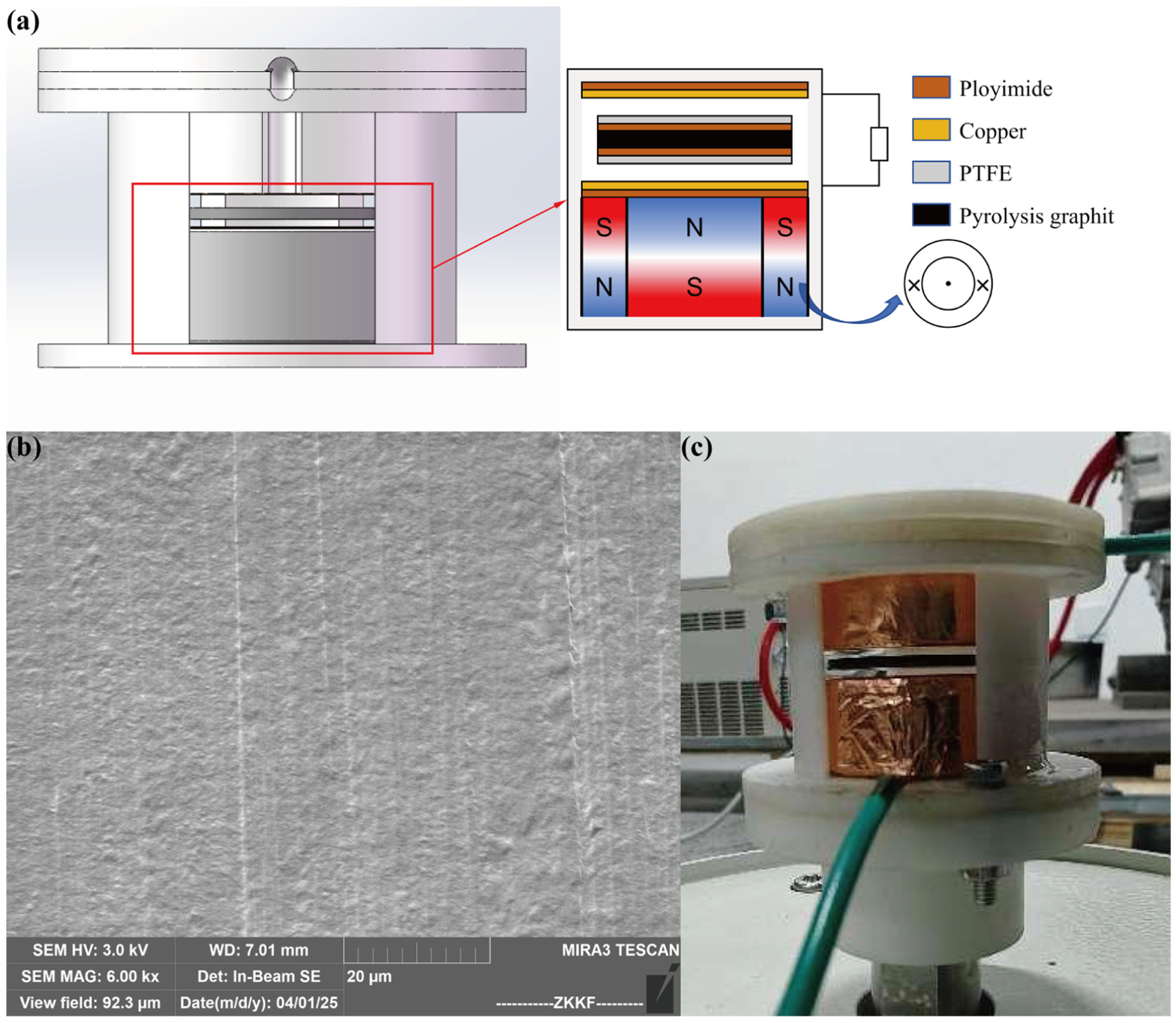
(a) Schematic diagram of the diamagnetic levitation triboelectric nanogenerator structure, (b) SEM image of the PTFE film, and (c) photograph of the diamagnetic levitation triboelectric nanogenerator prototype.
Working principle
According to the triboelectric effect and electrostatic induction principles, when the contact separation mode independent-layer TENG is subjected to external excitation—either from ambient vibration or variations in a magnetic field—the negatively charged free layer oscillates between two fixed electrodes. This motion induces an alternating electron flow through the external load connected to the fixed electrodes, schematically illustrated in Figure 2(a).
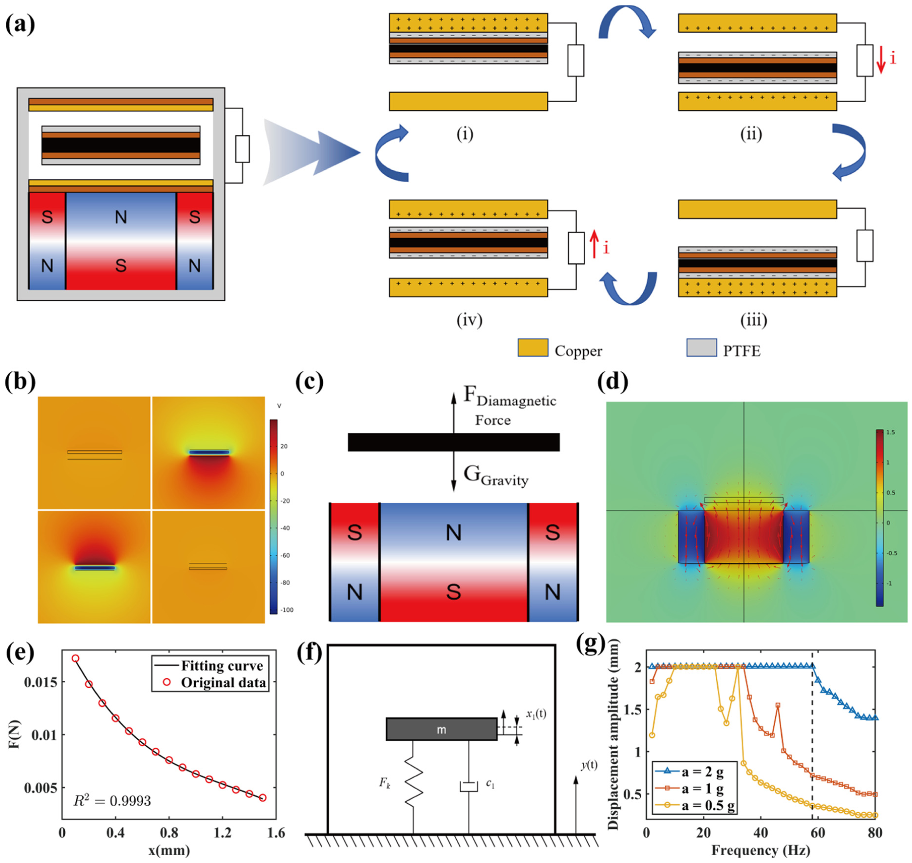
(a) Working mechanism of the contact-separation mode independent-layer triboelectric nanogenerator, (b) potential distribution under open-circuit conditions simulated by COMSOL, (c) force analysis of the pyrolytic graphite sheet, (d) simulation cloud map of the diamagnetic levitation system, (e) dependence of diamagnetic force on distance, (f) excitation response model, and (g) response amplitude versus excitation frequency of the pyrolytic graphite sheet.
A typical operational cycle is illustrated as follows. When the negatively charged free layer contacts the upper electrode, all positive charges generated by triboelectric interaction are attracted to the upper electrode, as shown in Figure 2(a). As the free layer moves from the upper electrode toward the lower electrode, a potential difference is established, with the upper electrode acquiring a higher electric potential. This drives electrons to flow from the lower to the upper electrode through the external load, generating a transient current. Notably, the direction of electron flow is opposite to the motion of the free layer, as depicted in Figure 2(a).
When the free layer contacts the lower electrode, the induced positive charges are transferred to the lower electrode, as illustrated in Figure 2(a). As the layer reverses direction and moves upward, electrons flow back to the lower electrode through the external load, producing a second current pulse, as shown in Figure 2(a). This reciprocating contact–collision–separation process, which cycles through stages (i)–(ii)–(iii)–(iv)–(i), as illustrated in Figure 2(a), generates a periodic alternating current that can be used to power external electronic devices.
This reciprocating contact–impact–separation process induces a periodic alternating current. The electrostatic field distributions of the contact-separation mode independent-layer TENG under four representative operational states were simulated using COMSOL Multiphysics under open-circuit conditions to further elucidate the working mechanism (Cui et al., 2022; Sun et al., 2021). The surface charge density was set to 1 × 10⁻⁶ C/m2, which was used to qualitatively validate the working mechanism (Pang et al., 2023; Zhang et al., 2024) and the variation trend illustrated in Figure 2(a). The simulation results are presented in Figure 2(b).
The pyrolytic graphite sheet functions as the independent layer in the diamagnetic levitation system, and its static force analysis is illustrated in Figure 2(c). The diamagnetic force per unit volume exerted on a diamagnetic material in an external magnetic field is given by (Simon et al., 2001):
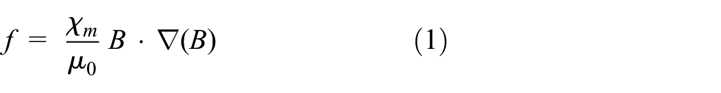
where B is the magnetic flux density generated by the magnetic base, μ0 is the vacuum permeability, and χ m is the magnetic susceptibility of the diamagnetic material. For diamagnetic substances, χ m is negative and typically very small, whereas for paramagnetic materials, χ m is positive.
Assuming that the magnetic susceptibility of the medium is uniform (Xu, 2019), the total diamagnetic force F acting on the diamagnetic material can be obtained by integrating equation (1) over the volume:
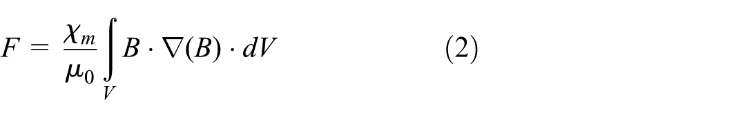
The force described in equation (2) is a complex nonlinear force; therefore, finite element simulations were performed in COMSOL based on equation (2) to analyze the diamagnetic levitation system, with the simulated cloud map shown in Figure 2(d). Based on simulations, the diamagnetic force acting on the pyrolytic graphite sheet at different distances from the magnetic base was calculated. The simulated variation trend was then fitted using a polynomial function, as illustrated in Figure 2(e), yielding the relationship between the diamagnetic force Ffitted and the distance x from the magnetic base:
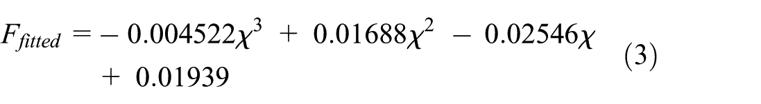
The fitted result of equation (3) is used to replace the diamagnetic force described in equation (2). When the upward diamagnetic force acting on the pyrolytic graphite sheet balances its gravitational force, static levitation is achieved. The corresponding position is defined as the static levitation point. By treating the net force resulting from the combined effects of gravity and diamagnetic interaction as an equivalent spring force, and considering the external excitation in the vertical direction as the system input, a single-degree-of-freedom forced vibration model can be established, as shown in Figure 2(f).
When the system is subjected to the magnetic field generated by a Helmholtz coil, the resulting time-varying magnetic field is approximately uniform within the central region. Accordingly, the total magnetic flux density at the pyrolytic graphite sheet can be expressed as :

where Bcoil denotes the magnetic flux density generated by the Helmholtz coil, Btotal denotes the total magnetic flux density at the pyrolytic graphite sheet. Substituting equation (4) into equation (2) yields:
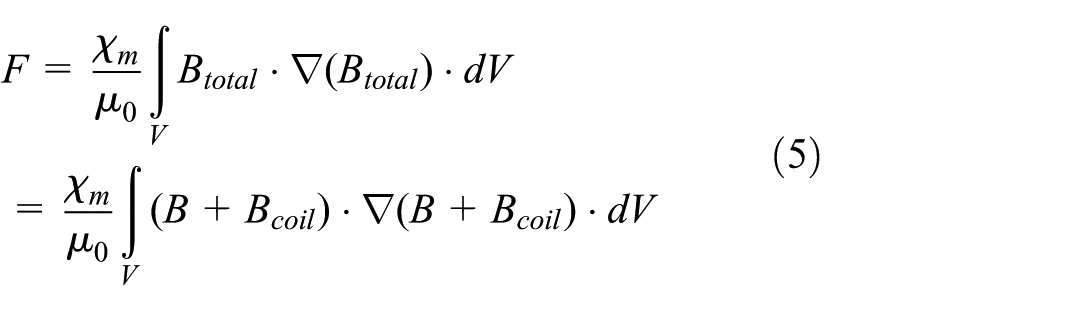
Since Bcoil is spatially uniform within the central region, its spatial gradient vanishes. Therefore, equation (5) can be simplified to:
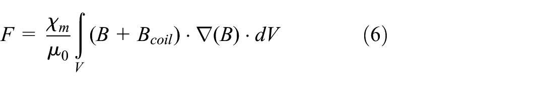
Decomposing equation (6) into two terms, the diamagnetic force acting on the pyrolytic graphite sheet under the additional magnetic field generated by the Helmholtz coil can be written as:
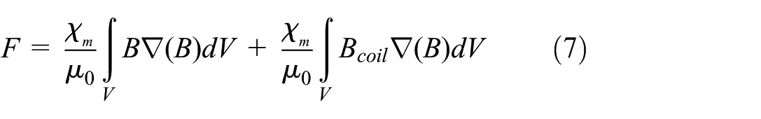
It can be seen from equation (7) that the magnetic force generated by the pyrolytic graphite sheet in response to the alternating current coil magnetic field can be regarded as an superimposed excitation term to the vibration system.
To estimate the dynamic response of the diamagnetic levitation system, equation (3) was adopted to describe the diamagnetic force, and a vibration response simulation model with vertical bilateral constraints was established in MATLAB/Simulink. Vibration excitation was applied to the system, and the relationship between the response amplitude of the pyrolytic graphite sheet and the excitation frequency under different acceleration levels was obtained, as shown in Figure 2(g). In the low-frequency excitation regime, the vibration amplitude increases with increasing excitation frequency. When the amplitude becomes sufficiently large for the pyrolytic graphite sheet to collide with the upper and lower surfaces of the prototype, the displacement reaches the maximum constraint limit. As the excitation frequency further increases, the vibration amplitude decreases and the collision behavior disappears, resulting in a sudden change in the response amplitude.
Output characterization
In the experimental evaluation, the energy harvesting performance of the diamagnetic levitation TENG was first examined separately under vibration and alternating magnetic field excitation. The open-circuit voltage signals were captured using a Tektronix 3 Series oscilloscope. Furthermore, the influence of the coupling phase difference on the output voltage was investigated under the condition that the excitation frequency of the alternating magnetic field matched the vibration frequency.
In the excitation experiments, a shaker was employed as the vibration source. As shown in Figure 3(a), the recorded data represent the open-circuit voltage output at an excitation frequency of 12 Hz with an acceleration amplitude of 1.34g, during which the pyrolytic graphite sheet repeatedly undergoes contact–separation impacts with both the upper and lower electrodes. As illustrated in Figure 3(b), the open-circuit voltage output measured at an excitation frequency of 20 Hz and an acceleration of 1.34g exhibits increased collision intensity, with the peak voltage reaching 2.42 V. The corresponding frequency spectrum is presented in Figure 3(c), revealing that the response signal is mainly composed of the excitation frequency and its second and third order harmonics. This frequency spectrum indicates that the independent layer undergoes vigorous oscillatory motion, repeatedly impacting both the upper and lower electrodes, and suggests the presence of a swinging dynamic behavior. In contrast, Figure 3(d) displays the open-circuit voltage under identical acceleration conditions (1.34g) but at an excitation frequency of 70 Hz. Under this condition, no contact occurs between the moving layer and the electrodes, and the peak voltage decreases to 1.31 V, reflecting a purely non-collisional response regime within the prototype. Figure 3(e) presents the variation of the root mean square (RMS) output voltage of the DL-TENG with excitation frequency under a constant acceleration condition. This variation trend corresponds well to the dynamic response curves shown in Figure 2(g). As the excitation frequency increases, the RMS output voltage initially rises and subsequently declines, reaching a maximum value of 2.17 V at 58 Hz, where the corresponding peak voltage is 5.30 V.
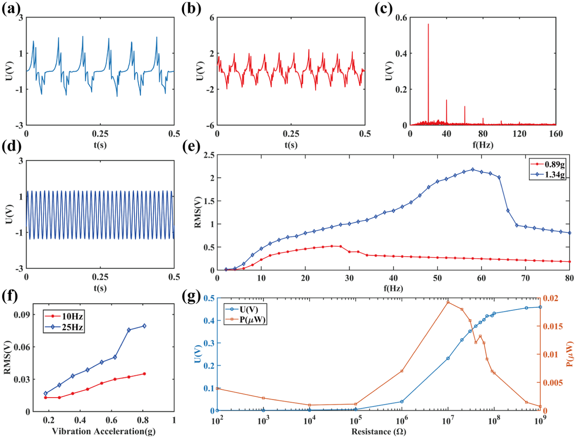
(a) Open-circuit voltage measured under an acceleration of 1.34g and an excitation frequency of 12 Hz, (b) open-circuit voltage measured under an acceleration of 1.34g and an excitation frequency of 20 Hz, (c) frequency response curve under an acceleration of 1.34g and an excitation frequency of 20 Hz, (d) open-circuit voltage measured under an acceleration of 1.34g and an excitation frequency of 70 Hz, (e) variation of the RMS output voltage of the diamagnetic levitation triboelectric nanogenerator with excitation frequency, (f) variation of the RMS output voltage with acceleration and (g) power versus load resistance of DL-TENG device.
Taking an excitation acceleration of 1.34g as an illustrative case, the response behavior of the system is analyzed. When the excitation frequency falls within the range of 2–10 Hz, the pyrolytic graphite sheet’s amplitude remains smaller than its static levitation height and the distance to the upper electrode, thereby preventing contact between the graphite sheet and the electrodes. In this regime, the device operates in a non-contact mode, corresponding to the reciprocating motion cycle illustrated in Figure 2(b)(ii)–(iv)–(ii), with no mechanical collisions occurring within the structure. The output voltage during this phase is primarily attributed to electrostatic induction. As the amplitude increases, the separation distance between the friction layers decreases, resulting in higher induced charge accumulation and increased surface charge density. Consequently, the output voltage exhibits a rapid increase with rising excitation frequency. When the excitation frequency exceeds 10 Hz, contact–collision–separation interactions occur between the pyrolytic graphite sheet and the upper and lower electrodes, corresponding to the complete operational cycle illustrated in Figure 2(b)(i)–(ii)–(iii)–(iv)–(i). In this frequency range, the voltage output results from the synergistic effects of electrostatic induction and triboelectric charge generation. As the frequency increases, the collision intensity is amplified, which enhances the interfacial contact between triboelectric layers and promotes the accumulation of surface charges. Consequently, a gradual increase in the output voltage is observed. Accordingly, within the excitation frequency range of 10–58 Hz, the RMS output voltage increases progressively due to enhanced triboelectric activity. However, the collision intensity diminishes as the excitation frequency exceeds 58 Hz. At 66 Hz, collisions between the pyrolytic graphite sheet and the electrodes cease entirely, leading to a marked reduction in vibration amplitude and a corresponding abrupt decline in output voltage. Beyond this threshold, further increases in excitation frequency result in continued attenuation of vibration amplitude, accompanied by a gradual decrease in output voltage. Figure 3(f) illustrates the dependence of the RMS output voltage on acceleration under a constant excitation frequency. The results indicate that higher acceleration levels increase output voltages, which can be attributed to more intense contact interactions between the triboelectric layers and improved energy conversion efficiency. Figure 3(g) shows the output power of the DL-TENG device under a vibration environment with a frequency of 50 Hz and an acceleration of 1.34g. When the load resistance is 107 Ω (10 MΩ), the power output is 1.92 × 10⁻² μW.
In experiments involving alternating magnetic field excitation, a Helmholtz coil is employed to generate magnetic fields, and the output performance of the DL-TENG is systematically evaluated. In this study, a Helmholtz coil with an inner diameter of 350 mm and an outer diameter of 620 mm, with a coil constant of 1.94 mT/A. A magnetic field is applied to the device through this coil, and the magnetic field deviation within the uniform field region (a spherical area with a diameter of 200 m) is within 5%. The magnetic field frequency is defined as the frequency of the alternating current supplied to the Helmholtz coil. The suspension height of the pyrolytic graphite sheet under different magnetic field strengths generated by the Helmholtz coil is shown in Figure 4(a). As shown in Figure 4(b), the open-circuit voltage is recorded at a magnetic excitation frequency of 30 Hz under varying magnetic field intensities, with a peak voltage of 204 mV observed at 22 mT. Figure 4(c) presents the frequency response of the DL-TENG under an 18 mT excitation at 30 Hz, where the primary response aligns with the excitation frequency, and additional peaks appear at its third and fifth harmonics. The trend of RMS output voltage with increasing magnetic field frequency under constant magnetic intensity is depicted in Figure 4(d), demonstrating a frequency-dependent response of the DL-TENG to magnetic excitation. Analysis of the three curves reveals distinct voltage fluctuations occurring at 14 and 50 Hz. Figure 4(e) and (f) illustrate the time-domain and frequency-domain responses of the DL-TENG under an environmental magnetic field excitation with an intensity of 18 mT and an alternating frequency of 14 Hz. Similarly, Figure 4(g) and (h) present the corresponding responses under the same magnetic field intensity at 50 Hz. In both cases, the frequency spectra exhibit minor components at the third harmonic of the excitation frequency, indicating the presence of nonlinear dynamic effects. Overall, the output voltage generated under vibration excitation is markedly higher than that obtained under magnetic field excitation, underscoring the enhanced energy conversion efficiency associated with mechanical excitation modes.
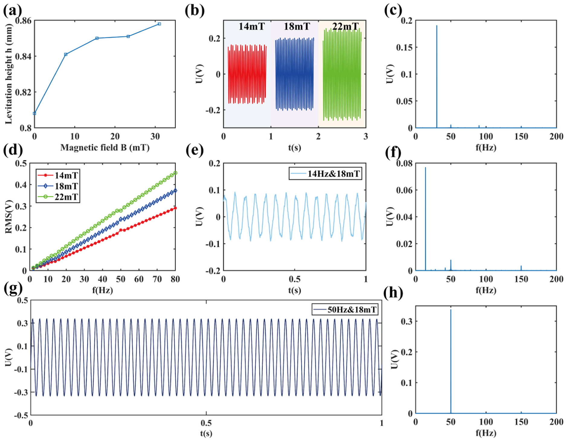
(a) Suspension height of the pyrolytic graphite sheet under different magnetic field strengths generated by the Helmholtz coil, (b) open-circuit voltage measured at an alternating frequency of 30 Hz under different magnetic field intensities, (c) frequency response curve under an alternating frequency of 30 Hz and a magnetic field intensity of 18 mT, (d) variation of the RMS output voltage of the diamagnetic levitation triboelectric nanogenerator with magnetic field frequency, (e and f) responses under an environmental magnetic field excitation with a magnetic field intensity of 18 mT and an alternating frequency of 14 Hz and (g and h) responses under an environmental magnetic field excitation with a magnetic field intensity of 18 mT and an alternating frequency of 50 Hz.
In the case of coupled excitation involving both environmental magnetic and vibration fields, the condition where the magnetic field frequency matches the vibration frequency is considered. Figure 5(a) illustrates the influence of coupling phase difference on the RMS output voltage. The data presented in Figure 5(a) correspond to measurements conducted at an excitation frequency of 40 Hz, a vibration acceleration of 0.89g, and a magnetic field strength of 22 mT. Under vibration-only excitation, the RMS output voltage reaches 909 mV, whereas under magnetic-field-only excitation, the RMS output voltage is limited to 207 mV. Under single-mode excitation, the output voltage remains independent of the phase. In contrast, under dual-mode vibration–magnetic excitation, two signal generators are phase-coupled, and the coupling phase difference is adjusted incrementally by 10° over a full cycle from 0° to 360°. As shown in Figure 5(a), the superimposed output voltage strongly depends on the phase difference between the excitation signals. The RMS output voltage varies accordingly, reaching a maximum of 1.198 V and a minimum of 708 mV.
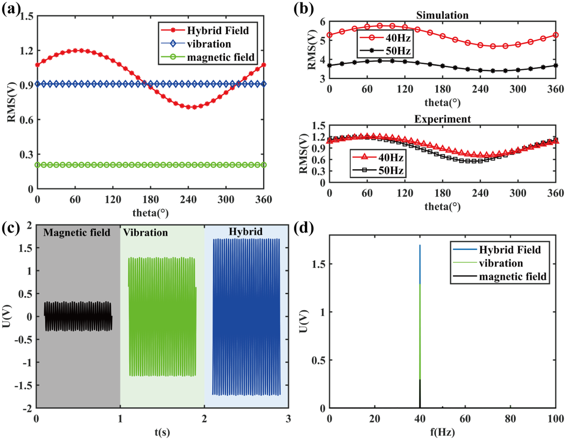
(a) Influence of the coupling phase difference on the output voltage under coupled excitation, (b) finite element simulation results and experimental results and (c and d) output voltage responses under different excitation modes with the same frequency.
The results in Figure 5(b) show the variation in the DL-TENG output voltage as a function of the phase difference between the vibration field and the alternating magnetic field at different frequencies. In this experiment, the vibration and magnetic field frequencies are kept constant, with a vibration acceleration amplitude of 0.89g and a magnetic field strength of 22 mT. The DL-TENG exhibits a significantly higher response to vibration excitation than magnetic field excitation. Therefore, when the excitation frequencies differ, the overall output of the DL-TENG shifts toward the vibration response characteristics with frequency, meaning that the coupled excitation output voltage at 40 Hz is generally greater than at 50 Hz, and both frequencies correspond to collisionless vibrations. Finite element simulation results also show a similar trend. In the COMSOL simulation, a qualitative analysis of the phase difference output characteristics was conducted.
Figure 5(d) displays the frequency response curves of the DL-TENG under different excitation modes-vibration only, magnetic field only, and coupled excitation—at a fixed frequency of 40 Hz, with a vibration acceleration of 0.89g and a magnetic field intensity of 22 mT. As shown in Figure 5(d), the dominant spectral peak frequency under vibration-only, magnetic-field-only, and coupled excitations remains unchanged, indicating that the external stimuli do not cause an observable shift of the dominant response frequency within the tested conditions. The amplitude of the primary frequency component under vibration-only excitation is 643 mV, which is substantially higher than that under magnetic-field-only excitation (146 mV). Under coupled excitation, the amplitude increases to 847 mV-exceeding the linear sum of the amplitudes obtained under the individual modes—suggesting a nonlinear enhancement effect due to vibration–magnetic coupling.
In daily life, we encounter various magnetic field environments. DL-TENG can detect magnetic fields generated by high-power household appliances, as the device exhibits a significant response capability to high-intensity magnetic fields. Figure 6(a) illustrates the detection process of a hair dryer’s magnetic field, where the vibration excitation frequency was set to 50 Hz and no mechanical collision occurred. Figure 6(b) displays the voltage output of DL-TENG under three conditions: vibration excitation alone, coupled vibration and hair dryer excitation, and hair dryer excitation alone. Figure 6(c) presents the amplitude of the dominant frequency of the output voltage across these three operating states. When the hair dryer is powered on, the voltage response significantly increases, indicating phase matching between the vibration and the applied magnetic field. It confirms that such magnetic fields can be utilized to drive self-powered sensors.
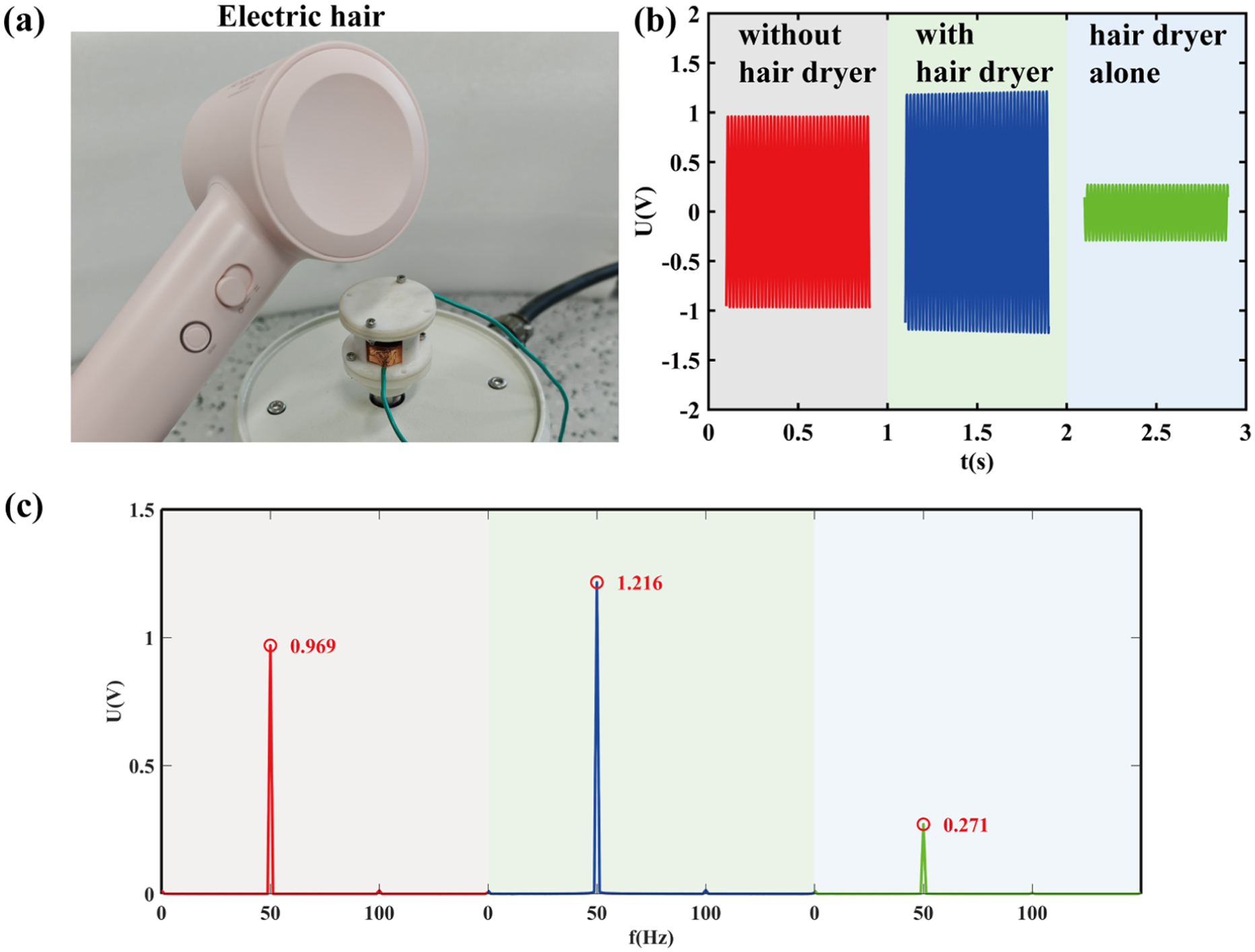
(a) Schematic diagram of DL-TENG for hair dryer magnetic field detection, (b) voltage response curves of DL-TENG devices under three operating conditions and (c) amplitude of the dominant frequency of the output voltage under three operating states.
Conclusions
This study proposes and experimentally verifies a novel dual-mode triboelectric nanogenerator based on diamagnetic levitation, designed to harvest energy from environmental mechanical vibrations and alternating magnetic fields simultaneously. The device achieves stable suspension and wide-frequency dynamic response without mechanical spring support by combining a contact-separation triboelectric structure with an diamagnetic levitation system using pyrolytic graphite sheets. Under vibration-only excitation conditions, the DL-TENG achieves a peak output voltage of 5.3 V at a frequency of 58 Hz and an acceleration of 1.34g; under magnetic field-only excitation conditions, at 30 Hz and 22 mT, a maximum output voltage of 204 mV is achieved. Notably, under dual-mode excitation, where vibration and magnetic field frequencies are matched, the output voltage increases by 31.7% compared to single-vibration excitation, exhibiting a highly phase-sensitive coupling effect. Furthermore, application experiments demonstrate that magnetic fields from high-power household appliances can be effectively detected and harvested by the DL-TENG, highlighting its potential for integration into self-powered sensors in real-world environments.
Although the results are encouraging, the study still has several limitations. First, the output power is relatively low under magnetic field excitation alone, limiting its independent application capability in specific high-energy-consuming scenarios. Second, while diamagnetic levitation structure effectively avoids mechanical wear, its response sensitivity to ultra-weak magnetic fields still needs improvement to meet the requirements of high-sensitivity magnetic field sensing.
Future research should focus on optimizing structural design and selecting friction materials to enhance power output per unit area. Integrating energy storage units and power management circuits could also improve its practicality in self-powered sensing networks. Furthermore, expanding the suspension structure into an array configuration or introducing multiphysics coupling mechanisms could open new avenues for efficient energy harvesting and multifunctional sensing in smart infrastructure, wearable electronics, and other fields.
Footnotes
Acknowledgements
The valuable comments and suggestions from anonymous reviewers are highly appreciated.
Ethical considerations
This study did not involve human participants, human data, human tissue, or animal experiments.
Funding
The authors disclosed receipt of the following financial support for the research, authorship, and/or publication of this article: The authors gratefully acknowledge the financial support from National Natural Science Foundation of China under Grants 52275233 and 52575262, and Beijing Nova Program under Grant 20250484816.
Declaration of conflicting interests
The authors declared no potential conflicts of interest with respect to the research, authorship, and/or publication of this article.
Data availability statement
The data that support the findings of this study are available from the corresponding author upon reasonable request.