Snap-through dynamics between the two potential wells of bistable oscillators are exhibited over a wide frequency range which narrows with decreasing harmonic excitation amplitudes until disappearing at a critical forcing level. However, for efficient conversion from vibrational to electrical energy in harvesting applications, the bistable oscillator must retain its favorable broadband cross-well response while the input excitation is minimized. To maintain effectiveness at low forcing levels, an actuation approach is proposed where external perturbations are used to extend the oscillator’s cross-well bandwidths by switching from co-existing low to high energy attractors. By utilizing Macro Fiber Composites (MFC) in a [/ bistable piezoelectric laminate, the application of rectangular voltage pulse signals are cycled through different response phases to continuously alter the basins of attraction until the desired cross-well orbit is sustained at each frequency. The pulse magnitude is where the system exhibits limit point behavior and the resulting snap through actuation mechanism brings consistency between perturbation trials. A multi degree of freedom electromechanical model that captures the stable shapes and cross-well dynamics and finite element analysis in Abaqus/Standard demonstrate the efficacy of the perturbation method. The model is then employed to significantly increase the bandwidths inducing cross-well oscillations.
Nonlinear vibration energy harvesters (VEHs) have become the subject of numerous works for powering small electronic systems within dynamic environments (Daqaq et al., 2014; Harne and Wang, 2013; Zhou et al., 2022). Their inherent wideband frequency response improves performance away from resonance as opposed to linear VEHs, which can only retain effectiveness within a narrow bandwidth. Power output rapidly decreases under operating conditions where the excitation frequency varies over time. Various implementations of nonlinear VEHs have included single-well (Daqaq, 2010; Mallick et al., 2016; Wang et al., 2021a), double-well (Erturk and Inman, 2011; Friswell et al., 2012; Wang et al., 2021a), and triple-well (Cao et al., 2015; Wang et al., 2021a; Zhou et al., 2016) systems associated with their potential energy functions. These are modeled with Duffing type equations which describe the behaviors of monostable, bistable, and tristable oscillators, respectively. Under harmonic excitation at low frequencies, bistable structures undergo snap through instabilities between their stable potential wells as periodic or aperiodic vibrations. These high amplitude cross-well oscillations enable greater power generation, often through piezoelectric transduction, over monostable structures confined within a single potential well (Daqaq, 2012; Masana and Daqaq, 2011). Due to nonlinear dynamical phenomena such as multistability and hysteresis, frequency responses can be branch into any of the co-existing stable steady state solutions which may include both low and high energy outputs. Which steady state solution a nonlinear VEH selects is driven by the excitation parameters and initial conditions. For Duffing oscillators, there has been much work on inducing escape from a potential well by quasi-statically varying a system parameter (Miller and Shaw, 2012; Thompson, 1989; Wright, 2016). Stewart et al. (1995) numerically varied the oscillator forcing amplitude, frequency, and damping coefficient to trigger a potential well escape. Virgin et al. (1992) used harmonic balance to predict critical forcing amplitudes that cause escape for a steady-state system response. Instead of quasi-statically varying control parameters, Udani and Arrieta (2018) demonstrated a transient perturbation method of triggering escape in bistable oscillators. In such systems exhibiting the co-existence of multiple stable attractors, attaining the desired steady state is critical for maintaining high energy transduction. Simultaneously, these same attractors’ sensitivity to perturbations vary considerably and forces control to be difficult. With varying excitation frequencies and amplitudes under real-world environments, efficient and reliable control mechanisms are necessary for maintaining high energy orbits to facilitate maximum energy conversion.
Different strategies for perturbing nonlinear VEHs from low energy to co-existing high energy orbits have been proposed to address this challenge. Zhou et al. (2015) imparted external mechanical shocks to magnetically induced bistable and tristable VEHs to achieve cross-well orbits. Wang et al. (2021b) investigated the use of an electromagnetic kick to initiate orbit jumps on a monostable electromagnetic energy harvester. Piezoelectric actuators or electrical circuits were coupled with oscillators to apply harmonic bursts (Mallick et al., 2016; Sebald et al., 2011) and voltage impulses (Lan et al., 2017) to induce jumps into high energy solutions, but the success of these methods were shown to be probabilistic and dependent on the electrical signal’s phase and amplitude. Udani and Arrieta (2017) proposed a perturbation method that characterizes and then selects co-existing high energy attractors by introducing a phase shift in the forcing signal through a piezoelectric actuation of a bistable composite laminate. Masuda and Sato (2016) utilized self-excited vibrations induced by a load resistance switching circuit to destabilize low energy oscillations and drive the electromagnetic VEH to jump into high energy orbits. Likewise, Wang and Liao (2019) perturbed beam structures by disconnecting the electrical loading to perform orbit jumps to enhance power generation performance. Huang et al. (2022) analyzed methods for sending buckled beam generators from low energy to high energy orbits through voltage inversion excitations. Zhou et al. (2021) created a Diptera-inspired design for a bistable VEHs, investigating performance under low-frequency excitations. The experiments and modeling showcased that energy harvesting efficiency was maximized during cross-well oscillations.
While the aforementioned methods were considered for isolated frequencies or narrow bandwidths, how these external perturbations can be applied to extend nominal cross-well bandwidths of bistable VEHs have been sparsely investigated. Under frequency sweeps with no external influence, cross-well bandwidths narrow with decreasing forcing amplitudes until disappearing at a critical excitation level. Disturbances are required for bistable VEHs to maintain their desirable broadband cross-well response in low amplitude conditions since they will likely remain in single-well orbits according to their basins of attraction. If stable high energy orbits can be accessed and maintained in multi-solution regions, nonlinear VEHs have been shown to exhibit wider corresponding bandwidths (Cammarano et al., 2014). Huguet et al. (2018) demonstrated this with an electromagnetic VEH in the form of a bistable buckled beam by placing it into co-existing subharmonic orbits through pulse disturbances.
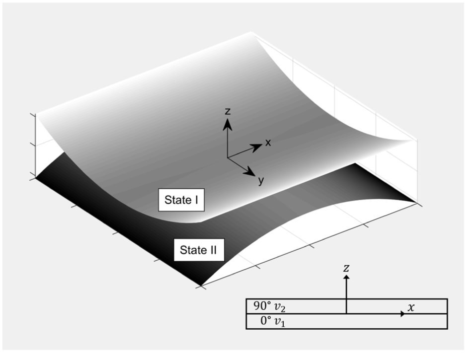
The objective of this paper is to numerically widen the global cross-well bandwidth of a bistable VEH by imparting perturbations whenever it is under single-well orbit. Classical frequency sweep characterization does not reveal all co-existent solutions, among which may be high energy orbits that extend the desired broadband response. The nonlinear oscillator is chosen to be a bistable composite laminate plate generated with the piezoelectric actuation of two P1 type Macro Fiber Composites (MFC) in a layup (Lee et al., 2017a, 2017b). Figure 1 presents its two stable cylindrical shapes, where the and MFC voltages are and , respectively.
The stable cylindrical shapes, layup, coordinate system, and state I and II definitions of a piezoelectrically generated bistable laminate.
Bistability is induced by bonding two actuated MFCs in the cross ply layup and shutting off the voltage post cure to produce in-plane residual stresses, which rise from the mismatch of the MFCs’ effective piezoelectric constants. This builds upon the conventional method of generating bistability in fiber-reinforced asymmetric composite plates by using residual thermal stresses that arise from the mismatch of the coefficient of thermal expansion between plies (Hyer, 1981; Jun and Hong, 1992). The existence of two potential wells is purely an elastic phenomenon that is inherent to the laminate and does not depend on clamps or magnets used for multistable beams. There has been many design extensions to bistable composite plates including connecting multiple laminates to induce more complex geometries or increase the number of stable states (Mattioni et al., 2009; Udani and Arrieta, 2019). The transition between the stable shapes occurs through a dynamic jump phenomenon known as a snap-through event and it is highly nonlinear in nature (Dano and Hyer, 2002). The MFCs simultaneously being the actuator and the primary structure alleviates the energy input requirement for snap through between either stable shapes, which is a general challenge for bistable composite plates driven by piezoelectric actuators (Schultz and Hyer, 2003). Therefore, complete configuration control is possible with the quasi-static voltage actuation of either MFC. By retaining sufficient actuation authority, the laminate has the capability to impart large perturbations to single-well orbits. When an MFC is the actuator , the other is assigned to be the energy harvester , thus enabling both functions without the need for additional piezoelectric transducers.
Electromechanical system
A multi degree of freedom (MDOF) Duffing-type oscillator model predicting the nonlinear dynamical behavior of the bistable laminate has been previously derived and experimentally verified (Lee and Inman, 2019). While single degree of freedom (SDOF) models can predict the dynamics of bistable VEHs (Udani and Arrieta, 2017), MDOF models are necessary to capture the stable cylindrical shapes of bistable composite laminates (Dano and Hyer, 1998; Diaconu et al., 2009). They exhibit nonlinear steady-state responses with deformation profiles that are dictated by the stable shapes, snap-through motion, and vibration modes (Arrieta et al., 2011a, 2011b; Lee and Inman, 2019); Wu et al., 2018). Since vibration-induced strains experienced by the laminate directly influences the generated power, accurately capturing the MDOF strain field and curvature states associated with the deformed profiles is critical for predicting the energy harvesting performance (Lee and Inman, 2019). Conversely, predicting how piezoelectric actuation changes the deformed laminate shape with the MDOF approach is necessary to model the snap-through dynamics that arise in the phase shift perturbation of bistable plates. This includes identifying the critical limit voltage that causes the snap-through and initiates the jump between co-existing responses. Past work (Lee et al., 2020) has demonstrated that the MDOF approach in this paper, when compared to experiments, can also accurately predict potential well manipulation and feedback control for vibration suppression that is inherent to the bistable laminate shapes.
As shown in Figure 1, the laminate coordinate system’s origin is placed at the geometric center, which is where the harmonic base excitation is applied and the edges are unconstrained. The derivation involves the nonlinear kinematic extension to classical lamination theory with Rayleigh-Ritz approximations of the mid-plane displacement and strain fields, which allows the plate motion to be described by five generalized curvature coordinates . The additional electromechanical coupling terms in the total potential energy are obtained from the piezoelectric constitutive equations, and provide the two generalized voltage coordinates and for each MFC. The seven electromechanical equations of motion are found from Lagrange’s equations and given below.
In equations (1) and (2), the mass matrix is , the nonlinear damping matrix is , the nonlinear stiffness matrix is , the electromechanical coupling matrix is , the forcing vector is , the capacitive matrix is , and is the load resistance. Variables enclosed in braces and brackets are vectors and matrices, respectively. The forcing vector contains the harmonic excitation function , where and are the forcing frequency and amplitude, respectively. and are the generalized curvature and voltage coordinates with the overdot indicating differentiation with respect to time. Since there is a mismatch in the number of degrees of freedom between and , the latter is defined as , where the and MFCs are and , respectively. All terms in the equations of motion are linear with the exception of and , which contain higher ordered quadratic and cubic curvature terms. The damping matrix is nonlinear due to it being partially proportional to the stiffness matrix from assuming Rayleigh damping as shown below.
The mass and stiffness damping coefficients are and , respectively. These parameters are obtained with the quadrature peak picking method from an experimental frequency response function (FRF) at low amplitude (Lee and Inman, 2019). The damping coefficients are found to be and , and these values are used in this paper. The state space form of equations (1) and (2) are given below where the state variables are defined as , , and .
To allow simultaneous MFC actuation and energy harvesting, the electromechanical system must be modified. Driven by a voltage source, serves as the actuation signal and control input to the system if the laminate is under single-well oscillations about state II, and if about state I. These assignments allow the MFCs to have adequate authority for inducing snap through due to their piezoceramic fiber alignment relative to the stable cylindrical shapes of the laminate (Lee et al., 2017b). The remaining voltage degree of freedom becomes the harvesting signal connected in parallel to the resistive load . Since the system loses an unknown degree of freedom to , the corresponding state space equation in equation (6) is dropped, and the remainder is shown below if and :
The resulting state space equations in equations (4), (5), and either (7) or (8) are assembled in MATLAB and numerically evaluated with the ode15 s ordinary differential equation solver with a time step of 0.0004 s. Under the inputs of the control signal , load resistance , base acceleration , and excitation frequency , the time dependent and responses are simulated for a given set of , , and initial conditions. The out-of-plane displacement of the laminate can then be found with the admissible fourth order polynomial shape function as given below.
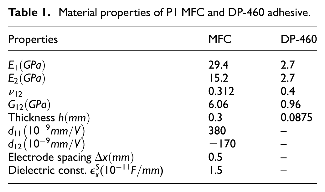
The bistable oscillator has an aspect ratio of 1, side lengths of 200 mm, and is designed to maximize the out-of-plane amplitudes between potential wells for favorable energy harvesting performance. The P1 type MFC associated with the effect is utilized for its actuation performance and strains in the piezoceramic fiber direction under an operating voltage of −500 to 1500 V. The DP-460 epoxy adhesive bonds the two MFCs in a flat configuration while they are actuated at the maximum voltage of 1500 V. The laminate bifurcates into its two stable states when the MFCs are unactuated post cure. The adhesive layer is modeled as an inactive isotropic ply between the two MFCs and its material properties along with those of the MFCs are provided in Table 1 (Kim et al., 2003; Williams, 2004). The overall laminate density (Lee and Inman, 2019) is kg/. The load resistance for is set to G to simulate open circuit conditions in all numerical simulations.
Material properties of P1 MFC and DP-460 adhesive.
Properties
MFC
DP-460
29.4
2.7
15.2
2.7
0.312
0.4
6.06
0.96
Thickness
0.3
0.0875
380
–
−170
–
Electrode spacing
0.5
–
Dielectric const. )
1.5
–
Results and discussion
Before cross-well bandwidths can be evaluated through frequency sweeps, the form of voltage perturbations for placing the bistable oscillator into co-existing high energy attractors must be defined. Unlike single degree of freedom (SDOF) Duffing oscillators where all stable co-existing attractors can be feasibly identified through either analytical or numerical methods, the MDOF system for the laminate contains six degrees of freedom and forces numerically integrated solutions to be computationally expensive. Since its basins of attraction cannot be efficiently characterized for a large range of system inputs, there are limitations to the solution searching strategies that can be effectively employed. Although more may exist, numerical forward and backward frequency sweeps reveal at most two co-existing steady state solutions for any given forcing level due to hysteresis, which is associated with amplitude jumps between single and cross-well orbits following either saddle node or period doubling bifurcation (Lee and Inman, 2019). It is possible that frequency bandwidths that exhibit single-well oscillations in both sweep directions also contain high energy solutions at the same excitation amplitude. Accessing the associated attractors are done in an exploratory manner through MFC voltage perturbations, which are necessary due to the disparity in the relative sizes of the basins of co-existing attractors at low forcing levels.
Low to high energy orbits with voltage perturbations
The form of voltage perturbation is chosen to be a rectangular pulse that is sequentially applied through the different phases of the forcing signal, or the oscillator’s out-of-plane displacement under single-well steady state vibrations. Since the basin of attraction that surrounds any generic attractor is highly sensitive to the response phase of the system (Lan et al., 2017; Mallick et al., 2016; Udani and Arrieta, 2017), changing the basins through phase shifts in a systematic fashion can lead the oscillator’s orbital trajectory to the desired high energy attractor. This is achieved by varying when the pulse is applied and constraining where it ends, which results in the oscillator’s position in the phase space at the end of the pulse to be kept approximately identical while the basins of attraction are continuously altered. Since all co-existing stable solutions are not pre-identified, it is not guaranteed whether this strategy will yield the desired cross-well orbit and the required computation time is unknown. Even if the oscillator successfully achieves the jump and maintains orbit, there may be additional stable attractors that could outperform the current solution in energy conversion.
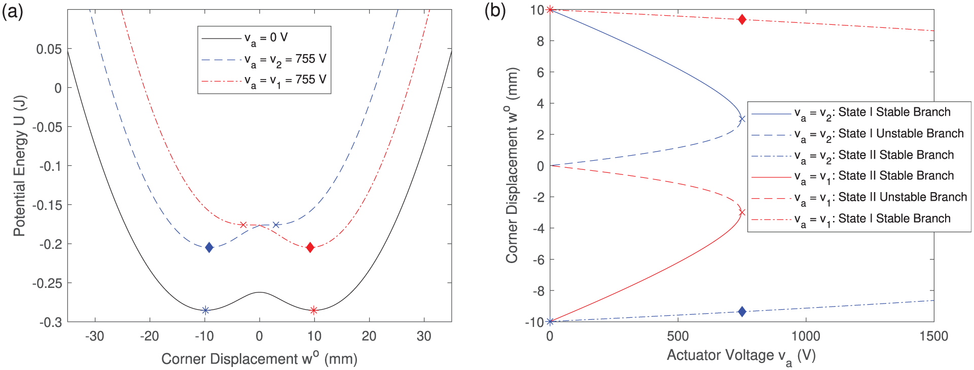
The amplitude of the voltage pulse is = 755 V, which is lowest value that induces quasi-static snap through between either stable states of the laminate. As seen in Figure 2(b), limit point behavior is exhibited at = 755 V where the initial stable branch will lose stability and jump to the second stable branch where it will remain regardless of what the actuation voltage is. Figure 2(a) shows that the corresponding potential well of the initial stable state disappears when = 755 V and forces the system into the remaining well. It will then remain monostable until is either lowered or removed. The markers show the corresponding points between the two plots to illustrate the relationship between and the elastic potential energy of the system. Since the elimination of the initial potential well is not affected by harmonic excitation levels, the laminate will always snap through to the other state at the limit voltage. This is advantageous in two ways, which are that the jump phenomenon associated with snap through occurs very quickly, and thus the duration of actuation and power requirement is lower than sinusoidal voltage excitation, which also reduces the net simulation time. The second is that snap through to the other state places the oscillator on a location of the phase space that has a higher chance of being outside its initial attractor’s basin of attraction. To ensure the consistency of this location, the voltage pulse ends when the corner out-of-plane displacement reaches its first peak post snap through which allows the corner velocity to be zero with every iteration. In this paper, the corner is chosen to be at mm assuming the origin is at the laminate center. This location is evaluated because it has significant out-of-plane deflections in both stable states, which is appropriate for evaluating cross-well orbits. It should be noted that this approach is a simplification of the higher-dimensional phase space representing the actual system and is used here for ease of implementation.
(a) Potential well elimination through static actuation of either or and (b) corresponding corner displacement versus or showing snap through between either stable shapes of the laminate.
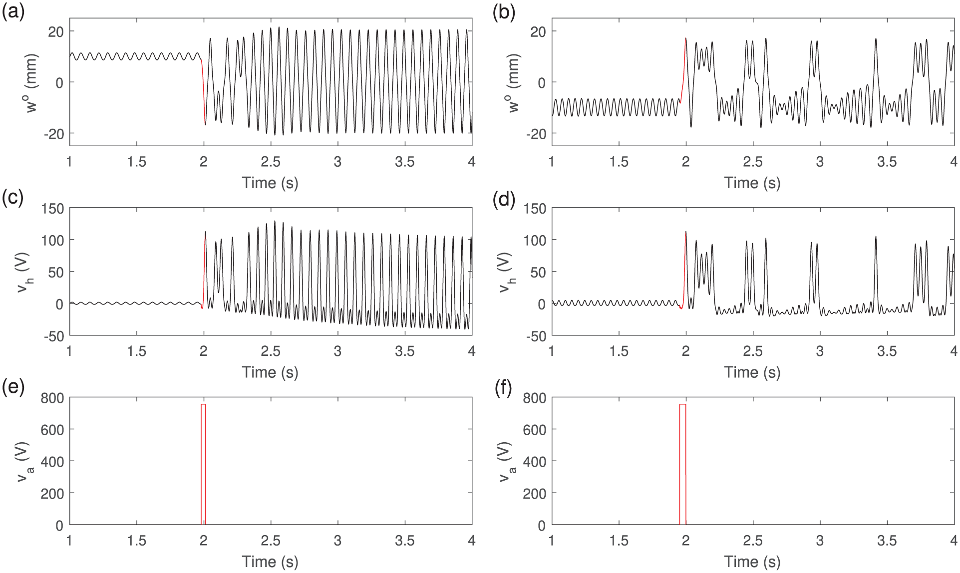
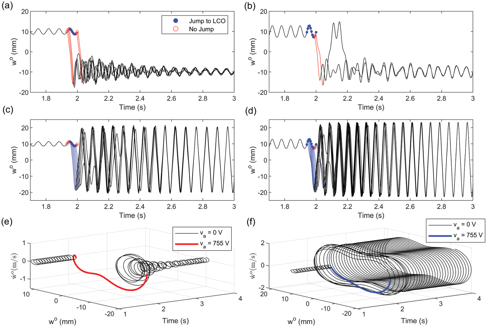
Two examples of switching from low to high energy orbits through a rectangular voltage pulse are presented in Figure 3 to illustrate the devised strategy. Figure 3(a), (c) and (e) show the corner displacement , harvester voltage , and actuator voltage time histories of the jump from single-well orbit about state I to high amplitude limit cycle oscillations (LCO) under the harmonic excitation of 15 Hz and 1.5 . Cross-well LCO in a bistable system is characterized by continuous snap-through events which allows a stable periodic high-energy orbit to be sustained between two potential wells. Resulting from large amounts of penetration into both potential wells, the periodic attractor motion have the largest amplitudes and therefore the highest power output of all cross-well regimes. Since the system is initially oscillating about state I, and . Figure 3(b), (d) and (f) show the switch from single-well orbit about state II to chaotic oscillations at 20.7 Hz and 1.5 , which is attributed by aperiodic snap through events through the strange attractor motion. This results in a broadband spectrum that retains vibrational energy over a wide bandwidth, but lower amplitudes and more infrequent snap through events make this response less favorable for energy harvesting than LCO. The laminate can also exhibit other cross-well regimes such as intermittency, subharmonic, and superharmonic oscillations (Lee and Inman, 2019), but are not shown here. Unlike LCO, the system is initially at state II, and so the voltage degree of freedom assignments are flipped so that and . The large amplitude difference of the harvester voltage between single-well and cross-well orbits in Figure 3(c) and (d) shows why the latter is preferred by VEHs, even at the upfront energy cost of voltage perturbations. Under a short duration, the net energy scavenged by nonlinear VEHs in high energy orbits post perturbation will far exceed what is harvested when they are in low energy orbits with no disturbances (Lan et al., 2017; Mallick et al., 2016; Udani and Arrieta, 2017; Wang and Liao, 2019; Zhou et al., 2021).
Jump from state I single-well to high amplitude limit cycle oscillations through a voltage pulse applied at rad phase difference from = 2 s under harmonic excitation of 1.5 and 15.0 Hz showing time histories of (a) corner displacement , (c) harvester voltage , and (e) actuator voltage . Jump from state 2 single-well to chaotic oscillations through a voltage pulse applied at rad phase difference from = 2 s under harmonic excitation of 1.5 and 20.7 Hz showing time histories of (b) corner displacement , (d) harvester voltage , and (f) actuator voltage . Red lines show time windows where where V.
In the simulations of Figure 3, the initial conditions for is set to be the curvatures corresponding to either state I or II while and V. Initially, the unactuated system V is solved until s to allow the oscillator to settle into a steady state solution. Then the system state , , and at serve as the initial conditions to the actuated system V, which is solved until reaches its first peak after snap through, or at . The system is then reverted back to the unactuated V at where the last state of actuated system is again carried over as initial conditions. If the jump into cross-well orbit is either not achieved or sustained for , then the time history is re-simulated with the voltage pulse V applied at a phase difference from . This procedure is repeated over one period of the single-well linear oscillations, where the phase difference is cycled through rad in - increments until there is a successful switch into a co-existing high energy attractor. If the switch never occurs within this range, the step size could be lowered and the solution search procedure repeated, but the desired attractor may also not exist. The number of perturbation attempts could indicate the difficulty of reaching the high energy orbit based on the relative size of its basin of attraction compared to that of the low energy orbit. For jumps into LCO and chaotic oscillations in Figure 3, successful switches are made at and from s, respectively.
To better illustrate how the phase shifts are induced by varying where is initiated, the system inputs from Figure 3(a), (c) and (e) under 1.5 and 15.0 Hz are taken to show all unsuccessful and successful switches from single-well oscillations to LCO in Figure 4(a) and (c), respectively. Figure 4(b) and (d) show the unsuccessful and successful jumps under a larger excitation of 2.5 and 17.0 Hz, respectively.
Numerically predicted jumps from state I single-well to limit cycle oscillations that are unsuccessful under harmonic excitation of (a) 1.5 and 15.0 Hz and (b) 2.5 and 17.0 Hz. Successful jumps under (c) 1.5 and 15.0 Hz and (d) 2.5 and 17.0 Hz excitation. Voltage pulses applied at rad phase differences from = 2 s in −0.2 steps. Blue and red markers show clusters of initial conditions where is activated that do and do not allow switching from low to high energy orbits, respectively. Corresponding blue and red lines show time windows where V. Orbital trajectories of an (e) unsuccessful and (f) successful jump into cross-well limit cycle oscillations under 1.5 and 15.0 Hz excitation.
The perturbation phase difference from s is cycled through in - increments. For these particular inputs under the 1.5 and 15.0 Hz excitation, the unsuccessful attempts are grouped into two clusters indicated by red markers, and range within and . The successful perturbations are indicated by blue markers and are grouped into a single cluster within . The red and blue lines show time windows where the rectangular voltage pulse is activated. For each iteration at , or where the pulse is removed, the resulting phase of the corner displacement corresponds to where is initiated. This indicates that changing the perturbation phase difference relative to will cause a controllable phase shift and alter the basins of attraction at . If the oscillator is placed in a co-existing high energy attractor’s basin of attraction, the switch will be successful. If the excitation level is raised to 2.5 at a similar frequency of 17.0 Hz, the number of successful attempts increase to two clusters where and . This indicates that the switch into LCO will require less attempts under larger harmonic excitation levels due to a greater number of phase shifts placing the oscillator in the LCO basin of attraction. All solutions following successful disturbances converge to the same limit cycle orbit in Figure 4(c) and (d) and those following unsuccessful disturbances converge to the same single-well orbit about state II in Figure 4(a) and (b). These behaviors suggest that the two solutions co-exist under the same input and no other attractors are present. Under 1.5 and 15.0 Hz excitation, Figure 4(e) and (f) present examples of unsuccessful and successful time dependent trajectories into high amplitude LCO from varying when the system is perturbed.
Finite element analysis
An implicit nonlinear finite element analysis (FEA) is conducted in Abaqus/Standard 2024 to compare and verify the bistable states, snap through behavior, and dynamic jumps between co-existing solutions from numerical simulations of the analytical model. The two MFCs in the bistable laminate is modeled with a uniform mesh consisting of 4 node quadrilateral shell elements with reduced integration (S4R) while the adhesive layer is uniformly meshed with 8 node quadrilateral continuum shell elements with reduced integration (SC8R). S4R are general purpose conventional shell elements that account for finite membrane strains and large rotations, so they are suited for large-strain analysis which the MFCs experience during actuation and cross-well oscillations. The elements also use reduced integration to form the stiffness, which keeps the computational cost low. Although there are other shell element types available, S4R elements offer a reasonable balance between computational efficiency and accuracy. The individual elements are all sized at 2.5 mm while each part has a side length of 200 mm and is flat in profile. Each MFC is coupled to the adhesive layer by imposing tie constraints between the master MFC surface and the slave adhesive surface. The material properties, damping coefficients, thickness, and the piezoceramic fiber orientation are defined through the composite layups definition for each part.
To simulate the voltage actuation for each MFC, a piezoelectric-thermal analogy approach (Côté et al., 2004) is adopted by applying the following linearized in-plane piezoelectric to thermal strain relationship:
where is the change in voltage, is the change in temperature, is the MFC electrode spacing, and are the in-plane piezoelectric constants, and and are the in-plane coefficients of thermal expansion (CTE). Equation (9) reveals that the in-plane thermal strains from a temperature change are analogous to in-plane piezoelectric strains generated by voltage actuation due to having the same form. The CTEs for each MFC are specified to be the piezoelectric constants divided by the electrode spacing so that any temperature change applied to the laminate is equivalent to an applied voltage change. is applied to each MFC through a predefined field. Any further mentions of MFC actuation will be in terms of the voltage input with the understanding that the thermal analogy approach is used.
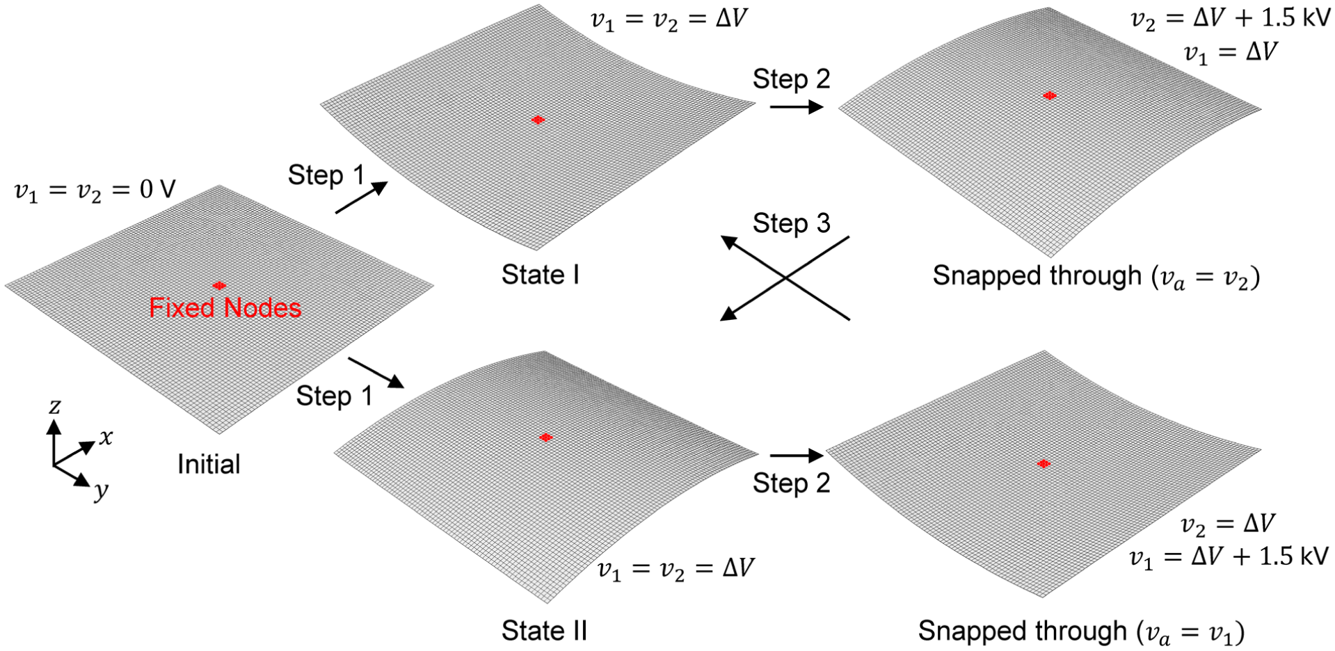
Figure 5 shows the Abaqus quasi-static analysis steps used to simulate the bonding of the actuated MFCs to generate the two stable cylindrical states, and the subsequent snap-through behavior from voltage actuation. It should be noted that quasi-static analysis in Abaqus/Standard is still a dynamic implicit simulation where existing inertial effects help with stabilization and solver convergence. The bottom ply is and the top ply is to match the definition used in the analytical model and Figure 1. Figure 6 shows the corresponding corner out-of-plane displacements and actuator voltage signal results from the quasi-static FEA.
Quasi-static FEA procedure for inducing two stable cylindrical states and snap through between these states through MFC actuation for a laminate.
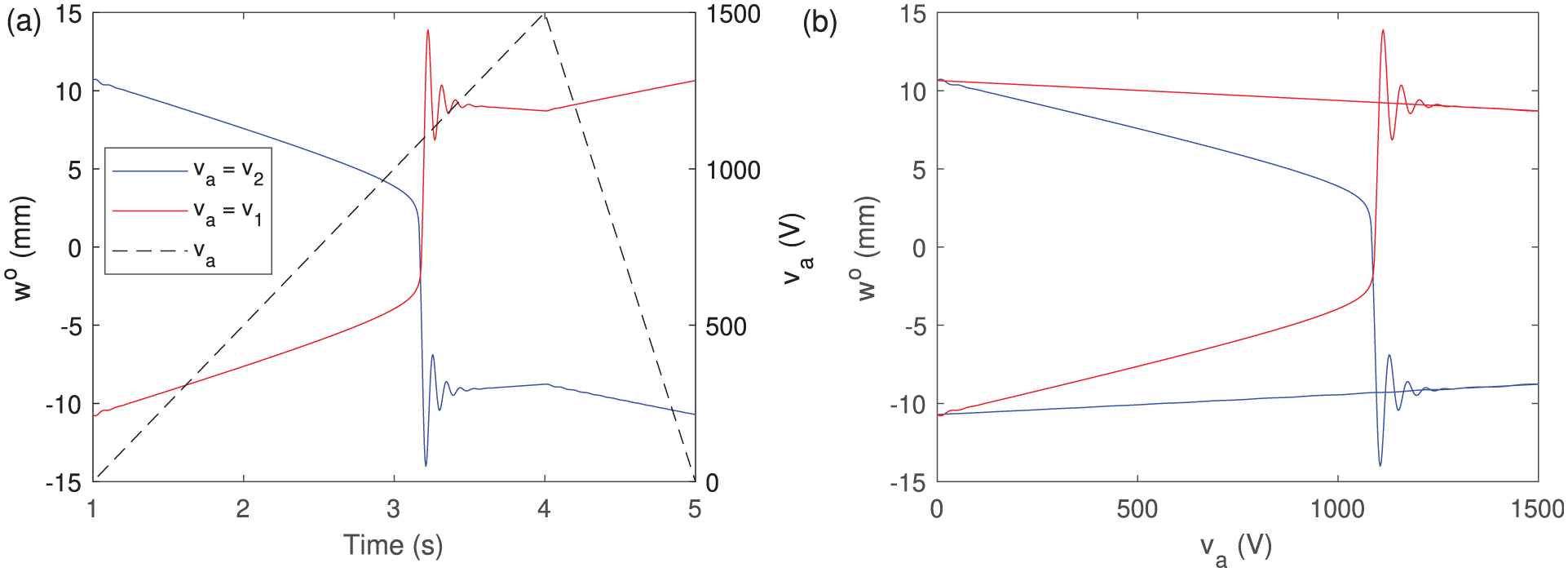
For and cases, (a) FEA corner displacement and and actuator voltage versus simulation time and (b) FEA versus showing snap through between states I and II.
Initially, the laminate is in a flat configuration with zero actuation and the center nine nodes are fixed to prevent any rigid body displacements or rotations during the simulation. In the first step, both MFC voltages are linearly ramped to V over 1 s and the laminate generates a curved profile before reaching state II with negative out-of-plane displacements. The is the bias voltage used to simulate the default bistable states of the laminate. In the next step from state II, the bottom MFC is linearly ramped back to V over 3 s to simulate voltage actuation from to 1500 V. During this step, the laminate displacement decreases until snap through eventually occurs from state II to state I at approximately V. This corresponds to when the laminate becomes unstable and begins to self-initiate the jump phenomenon. The FEA snap through voltage is found to be greater than the analytical snap through voltage of 755 V. The inertia generated from snap through manifests as free vibrations which are quickly dissipated by numerical damping in the quasi-static analysis. In the final step, is linearly ramped back down to 0 V over 1 s and the laminate reaches state I with positive .
To simulate the snap through from state I to II, a separate simulation is conducted where during the first step with application, a concentrated force of 0.5 N is applied in the positive direction at the four corner nodes for the first 0.25 s, which biases the laminate toward state I. Once state I is reached, the top MFC is linearly ramped back to V to simulate voltage actuation from to 1500 V. During this step, snap through to state II occurs where the jump is also initiated at approximately V. In the final step, the voltage is removed and the laminate reaches state II with negative . Figure 6 shows that the laminate corner displacements and their variation are largely mirrored between the two simulations. When comparing the FEA with the analytical predictions in Figure 2, the corner displacements show fairly good agreement where for states I and II, the FEA and mm while the analytical and mm, corresponding to percent errors of 7.9% and 8.6%, respectively. Comparing Figure 2(b) to Figure 6(b) shows that the corner displacement variation with respect to the actuator voltage exhibits mirrored snap through instability between either stable states for both the analytical model and FEA. Although the snap through voltage is larger for the FEA, the verified laminate response to MFC actuation forms the basis for conducting dynamic jumps between linear single-well and nonlinear cross-well oscillations.
To simulate dynamic switches from low to high energy orbits, the quasi-static FEA in Figure 5 is modified after cylindrical state I is achieved at the end of the first step. In the second step starting at s, the implicit nonlinear dynamic analysis application is changed to transient fidelity, which is intended to minimize numerical damping, induce smaller solver time increments, and accurately resolve the vibrational response of the structure. While the MFC voltages remain unchanged, base harmonic excitation is induced through a velocity boundary condition in the out-of-plane direction for. This boundary condition is applied to the nine center nodes that were previously fixed. The corresponding amplitude is periodic and the waveform definition with the velocity magnitude ensures harmonic excitation with a specified acceleration and frequency. In the third step starting at s, the harmonic excitation remains unchanged and the first 1 s allows the laminate to settle into steady state oscillations about state I. Then at s, is linearly ramped to the FEA snap through voltage of 1017.5 V over s. This voltage is sustained until reaches its first negative peak after snap through, where after is ramped back down to 0 V at the same rate. The vibrational response is then simulated until s. To simulate phase shifts in the system, voltage perturbation phase differences from s is cycled through in 0.2 increments. This is achieved in Abaqus through job restarts at s where each restarted simulation has the actuation timing adjusted accordingly through the amplitude definition.
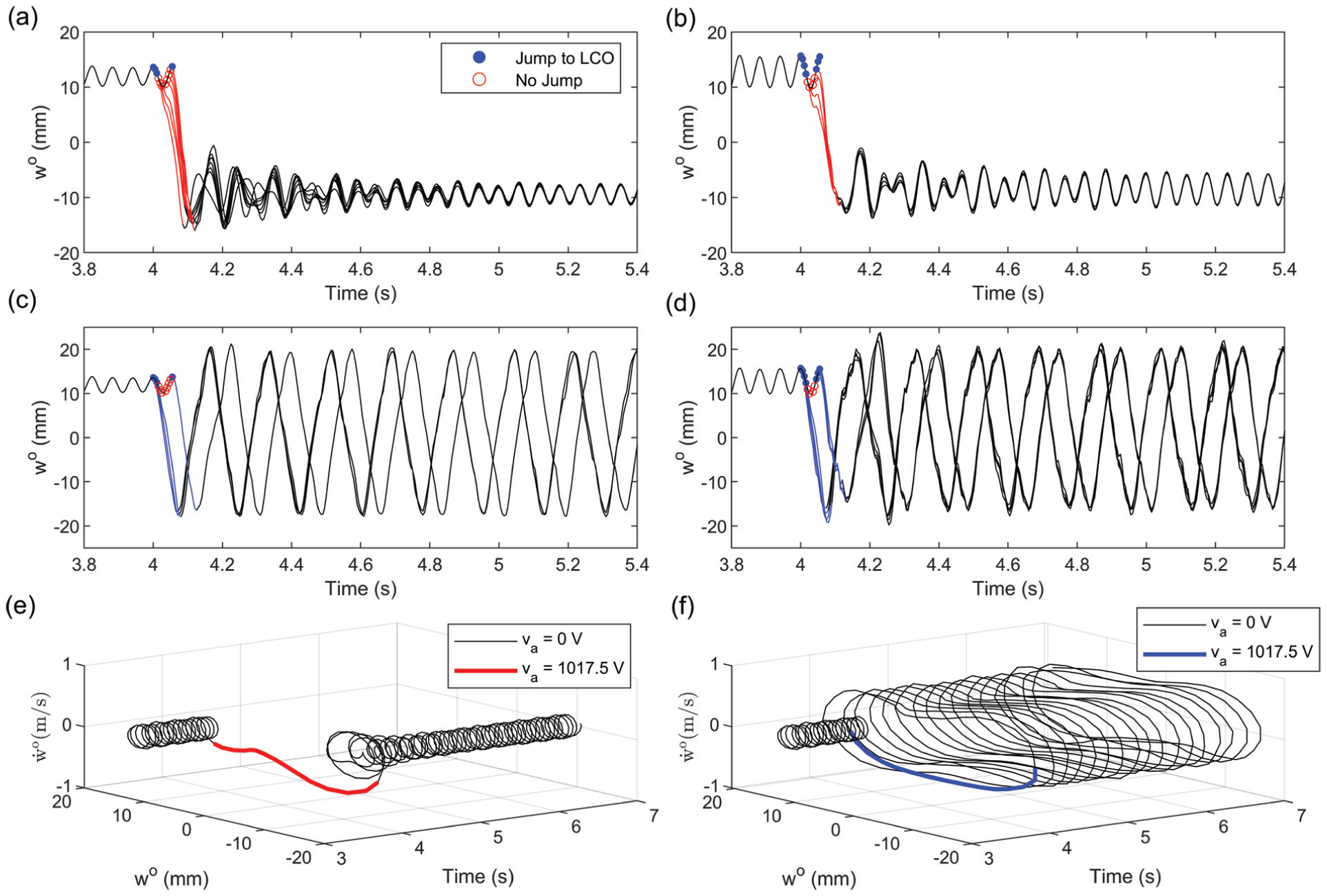
Figure 7(a) and (c) show all simulated unsuccessful and successful jumps, respectively, from single-well oscillations to LCO with example orbital trajectories in Figure 7(e) and (f), all under 1.5 and 17.0 Hz. Figure 7(b) and (d) shows all unsuccessful and successful jumps, respectively, into LCO under 2.5 and 17.0 Hz. Similar to Figure 4, the perturbation phase difference is cycled through from s, unsuccessful and successful attempts are indicated by red and blue markers, respectively, and the red and blue lines show the duration in which the snap through voltage pulse is active. Unlike the numerical results in Figure 4, FEA does not predict any successful jumps into LCO at 1.5 and 15.0 Hz. However, it does predict a similar number of successful attempts (i.e. four attempts in FEA and six attempts in the analytical model) and at a nearby excitation frequency of 17.0 Hz, where the successful attempts are grouped within and . Once LCO is achieved, the FEA peak to peak amplitude is approximately 37.5 mm, which shows good agreement with the analytical LCO peak to peak amplitude of 40.4 mm, where the percent error is 7.7%.
FEA jumps from state I single-well to limit cycle oscillations that are unsuccessful under 17.0 Hz harmonic excitation at (a) 1.5 and (b) 2.5 . Successful jumps under (c) 1.5 and (d) 2.5 under 17.0 Hz excitation. Voltage pulses applied at rad phase differences from = 4 s in 0.2 steps. Blue and red markers show clusters of initial conditions where is activated that do and do not allow switching from low to high energy orbits, respectively. Corresponding blue and red lines show time windows where V. FEA orbital trajectories of an (e) unsuccessful and (f) successful jump into cross-well limit cycle oscillations under 1.5 and 17.0 Hz excitation.
There is better agreement in the response if the acceleration is raised to 2.5 where at the same excitation frequency of 17.0 Hz, FEA predicts a larger number of successful attempts in two phase difference clusters of and . FEA shows seven successful attempts, which correlates with the increased number of successful jumps predicted by the analytical model at nine attempts. The FEA LCO peak to peak amplitude slightly increases to approximately 38.5 mm, but the relative increase does not match the analytical LCO peak to peak amplitude of approximately 46.1 mm, resulting in an increased percent error of 19.7%. Beyond the differences in formulation and implementation, the discrepancy in successful phase angles between the numerical predictions and FEA highlights how the phase shifts must be tailored to appropriately alter the basins of attraction for any particular system.
The FEA shows that all responses following unsuccessful disturbances converge to the same single-well orbit about state II, which is in agreement with Figure 4. However, the LCOs following successful response jumps converge to two separate cross-well orbits with a clear phase difference under both excitation levels. This response suggests that two high energy attractors co-exist under the same input and which solution the oscillator lands on depends on how the phase shift alters each basin of attraction. Additionally, once the switch into LCO occurs, the frequency of oscillation decreases to a third of the excitation frequency, but the laminate still exhibits continuous and periodic snap-through motion between the two stable states. Although the LCO orbital trajectory is maintained as shown in Figure 7(f), the frequency drop lowers the peak velocities achieved in the high energy orbit. Regardless, this cross-well response remains much more favorable for energy harvesting applications compared to single-well oscillations.
Cross-well bandwidth enhancement in frequency sweeps
With the method established for perturbing the bistable oscillator from low to high energy orbits, how this can be used to extend the cross-well bandwidth of the system is now investigated. For bistable VEHs to maintain effectiveness under a broadband environment at lower forcing levels, their narrowed nominal high energy bandwidths must be widened. This enables access to co-existent cross-well attractors at frequencies where the oscillator cannot escape from single-well orbits without any external disturbances.
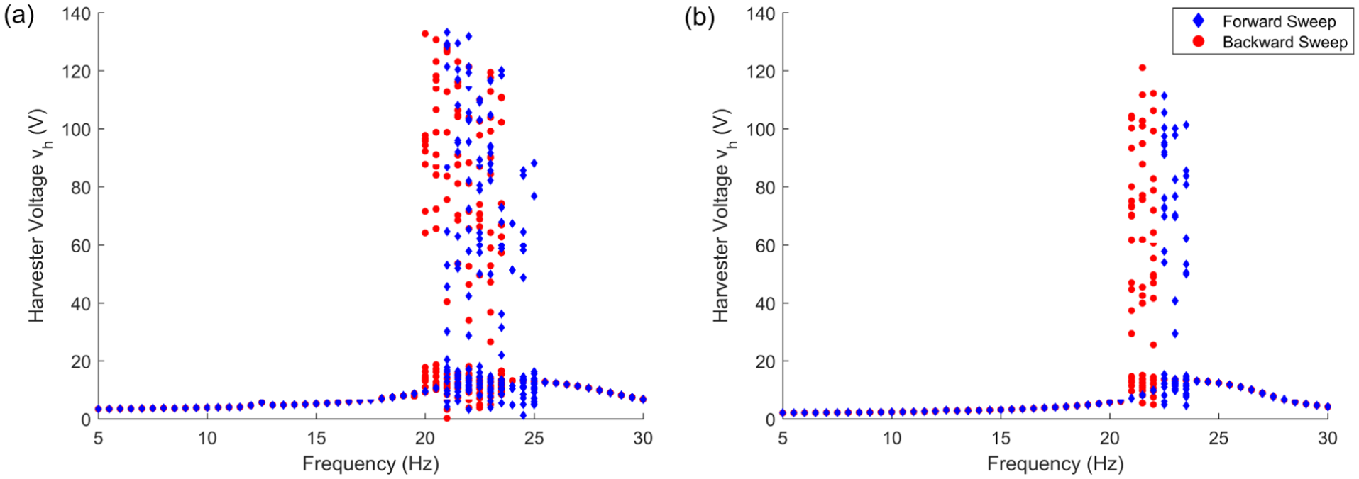
For the unactuated system, Figure 8(a) and (b) present the numerical forward and backward frequency sweep results from 5 to 30 Hz in 0.5 Hz increments at 2.5 and 1.5 , respectively. Peak to peak amplitudes of the harvester voltage are obtained from simulated time histories with stroboscopic sampling at each excitation frequency over several forcing periods. At each frequency, samples appear as a single point for linear single-well oscillations at low amplitudes and cross-well limit cycle or superharmonic oscillations at high amplitudes. Samples appear as multiple points for nonlinear responses including intermittency, subharmonic, and chaotic oscillations, and retain much larger amplitudes than their single-well counterparts.
Stroboscopically sampled peak to peak harvester voltage amplitudes during forward and backward frequency sweeps at (a) 2.5 and (b) 1.5 from initial state I for the unactuated V system.
Before the frequency sweeps are performed, the initial conditions for are set to be the curvatures corresponding to state I, and . During the sweeps for each frequency, the , , and states of the final time step are used as the initial conditions for the next excitation frequency while . For both forcing levels, hysteretic regions between the sweep directions separate the boundaries between single and cross-well regimes as characterized by large amplitude jumps. The cross-well responses appear around the first plate bending mode which undergoes softening where its resonant peak is pushed below its natural frequency. At 2.5 , the nominal cross-well bandwidths are 21, 25, 20, and 23.5 Hz in the forward and backward sweep directions, respectively. These bandwidths shrink at the lower forcing level of 1.5 , where they are 22.5, 23.5, 21, and 22 Hz in the forward and backward sweep directions, respectively. The peak amplitudes also decrease with the lower excitation level. The simulated frequency sweep results have been previously validated with experimental sweeps conducted on a 200 by 200 mm bistable laminate through a shaker setup (Lee, 2019; Lee and Inman, 2019).
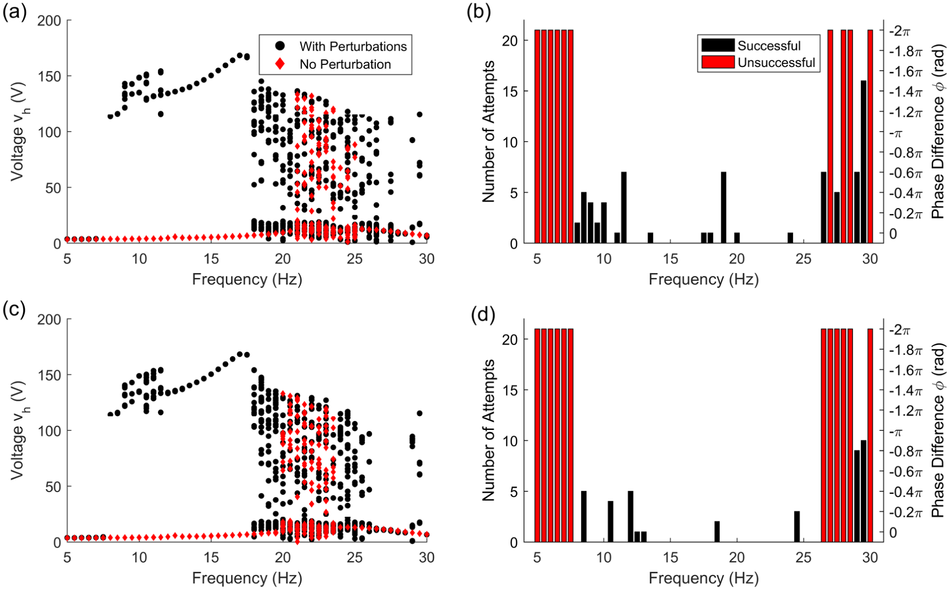
From these nominal sweeps, the results for how the oscillator’s high energy bandwidth changes when voltage perturbations are introduced into the system are shown in Figure 9(a) and (c) for forward and backward frequency sweeps at 2.5 , respectively. As described in the previous section, the procedure of cycling the activation of the rectangular voltage pulse V through rad phase difference from is applied whenever the oscillator is in single-well orbit at each frequency step. If it is already in cross-well orbit, then the system is left unperturbed and the sweep is continued. The sample step size is chosen to be - , and the solution search procedure is ended either when there is a successful jump into a co-existing high energy attractor, or the oscillator fails to switch after cycling through the entire range. The latter case does not necessarily mean that the desired co-existent attractor does not exist since an initial condition leading to the proper phase shift may have been missed. If it does exist, then the number of attempts describe the difficulty of accessing this solution. Although the step size could be lowered or altered, this was not implemented to keep computation times manageable.
Stroboscopically sampled peak to peak harvester voltage amplitudes with and without voltage perturbations during (a) forward and (c) backward frequency sweeps at 2.5 from initial state I. Corresponding number of voltage perturbation attempts and phase difference between when rectangular pulse is activated and for (b) forward and (d) backward frequency sweeps.
Figure 9(b) and (d) reveal how many perturbation attempts were made while sampling through in the forward and backward sweep directions, respectively. None being made indicates that the system is already under cross-well oscillations. At any given frequency step, if , , and the oscillator is under single-well orbit about state II, then the MFC harvester and actuator assignments are flipped (, ) when the voltage pulse is activated so that snap through can be initiated. If the single-well orbit is about state I, , and , then the assignments are also flipped when is applied.
The application of voltage perturbations in both sweep directions reveal co-existing cross-well attractors at excitation frequencies well beyond the nominal high energy bandwidths and their hysteretic regions shown in Figure 8(a). The extended bandwidths show distinct regions of similar nonlinear responses with varying levels of accessibility. For the forward sweep, 7.5–11 Hz exhibit a mix of subharmonic and super harmonic oscillations, then the response changes to LCO until 17 Hz. From this frequency, the oscillator undergoes a mix of intermittency, chaotic, and subharmonic oscillations until 26.5 Hz, and the total resulting cross-well bandwidth is 19 Hz, which is a 375% increase from the nominal 4 Hz of the unperturbed system. The backward sweep shows identical responses with the exception of its bandwidth’s upper boundary being 26 Hz. This results in a total bandwidth of 18.5 Hz, which is a 429% increase from the nominal size of 3.5 Hz.
The near identical responses between sweep directions suggest that the solution searching procedure is thorough enough to not be influenced by hysteresis. However its effects can be observed in the number of perturbation attempts needed for jumping into the high energy attractor. Below 11 Hz, the backward sweep requires less trials to access the subharmonic and super harmonic orbits due to the initial conditions being carried from the frequencies above when the system undergoes high amplitude LCO. At isolated frequencies beyond the upper boundary of the extended bandwidth, the forward sweep is able to access more co-existing high energy attractors. For both directions, the regions corresponding to LCO and the nominal cross-well bandwidths require less attempts. This suggests that their basins of attraction are larger compared to those of the low energy attractors and more accessible than the solutions in other regions. The significant bandwidth extensions demonstrate the perturbation strategy’s effectiveness in enhancing the bistable oscillator’s energy harvesting performance.
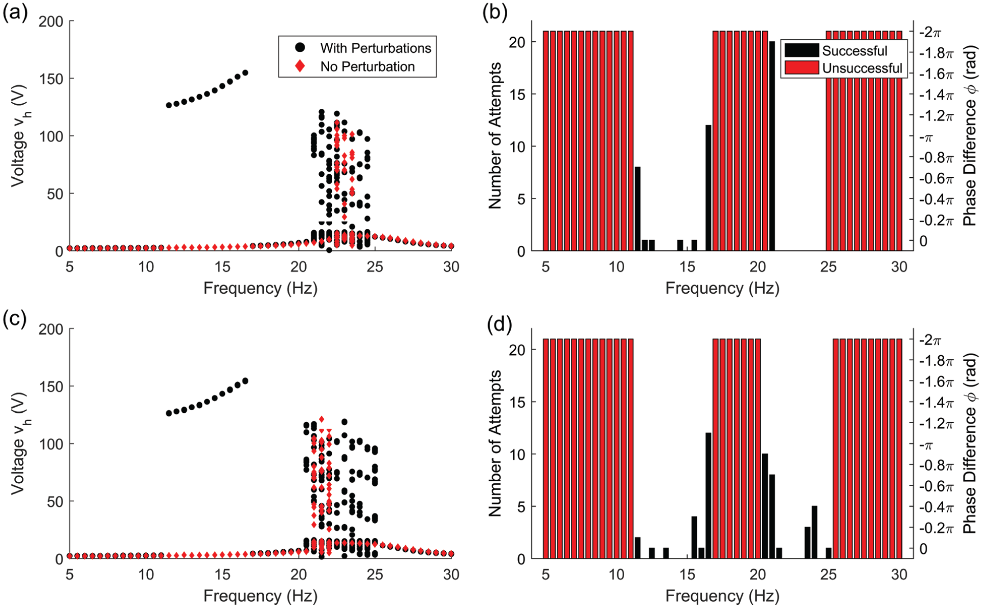
To determine if the cross-well bandwidth extension from voltage perturbations can be maintained at a lower forcing level, frequency sweep results at 1.5 are shown in Figure 10(a) and (b) in the forward direction and (c) and (d) in the backward direction. The large bandwidth enhancement achieved at 2.5 becomes divided into two narrower regions, where the first is 11.5–16.5 Hz containing LCO as the co-existing attractor, and the second is 21–24.5 Hz for the forward sweep and 20.5–25 Hz for the backward sweep. Relative to their nominal bandwidths from Figure 8(b), the combined extended bandwidths are 750% and 850% increases for the forward and backward sweeps, respectively. The frequency ranges between the two regions and below the first LCO region remain under single-well oscillations due to the co-existing high energy attractor’s basins of attraction either diminishing or entirely disappearing. At 2.5 , the cross-well regions that on average took a higher number of attempts for successful perturbations now remain in low energy orbit through the 1.5 sweeps. Although the range of frequencies where the bistable oscillator can sustain high power output is still enhanced including access to the desirable LCO, the size of the extended bandwidth decreases with lower forcing levels.
Stroboscopically sampled peak to peak harvester voltage amplitudes with and without voltage perturbations during (a) forward and (c) backward frequency sweeps at 1.5 from initial state I. Corresponding number of voltage perturbation attempts and phase difference between when rectangular pulse is activated and for (b) forward and (d) backward frequency sweeps.
Conclusions
A perturbation strategy of initiating jumps between single-well to cross-well orbits through rectangular voltage pulses is utilized for widening the high energy bandwidths of a bistable piezoelectric plate oscillator. The highly energetic response resulting from large amplitudes and broadband spectrum of cross-well oscillations result in greater power generation for bistable VEHs when compared to what linear vibrations can yield. By accessing their associated co-existing attractors through external disturbances, the oscillator’s energy harvesting performance can be enhanced through the extension of effective operational conditions. Phase shifts in the system response are induced by controlling when the voltage pulses are applied to alter the basins of attraction until the oscillator lands on the desired attractor. While most bistable VEHs are modeled with a SDOF Duffing-type oscillator system, this paper’s contribution is the electromechanical MDOF Duffing-type oscillator model capable of capturing the stable shapes, snap-through motion, and cross-well dynamics associated with the square bistable laminate. The jumps between co-existing responses of the oscillating bistable plate are demonstrated with numerical simulations of the MDOF model and finite element analysis in Abaqus/Standard. With the perturbations, cross-well bandwidths show 375% and 429% increases in numerical forward and backward frequency sweeps at 2.5 , respectively. These increases are enlarged to 750% and 850% when the forcing is lowered to 1.5 for forward and backward sweeps, respectively.
Footnotes
Data Availability Statement included at the end of the article
ORCID iD
Andrew J. Lee
Funding
The authors disclosed receipt of the following financial support for the research, authorship, and/or publication of this article: This work was supported by the US Air Force Office of Scientific Research (AFOSR) under grant number FA9550-16-1-0087 and the Department of Mechanical and Aerospace Engineering at North Carolina State University.
Declaration of conflicting interests
The authors declared no potential conflicts of interest with respect to the research, authorship, and/or publication of this article.
Data availability statement
The datasets generated during and/or analyzed during the current study are available from the corresponding author on request.*
References
1.
ArrietaAFNeildSAWaggDJ (2011a) On the cross-well dynamics of a bi-stable composite plate. Journal of Sound and Vibration330(14): 3424–3441.
2.
ArrietaAFSpelsberg-KorspeterGHagedornP, et al. (2011b) Low order model for the dynamics of bi-stable composite plates. Journal of Intelligent Material Systems and Structures22(17): 2025–2043.
3.
CammaranoANeildSABurrowSG, et al. (2014) The bandwidth of optimized nonlinear vibration-based energy harvesters. Smart Materials and Structures23(5): 055019.
4.
CaoJZhouSWangW, et al. (2015) Influence of potential well depth on nonlinear tristable energy harvesting. Applied Physics Letters106(17): 173903.
5.
CôtéFMassonPMradN, et al. (2004) Dynamic and static modelling of piezoelectric composite structures using a thermal analogy with MSC/NASTRAN. Composite Structures65(3-4): 471–484.
6.
DanoMLHyerMW (1998) Thermally-induced deformation behavior of unsymmetric laminates. International Journal of Solids and Structures35(17): 2101–2120.
7.
DanoMLHyerMW (2002) Snap-through of unsymmetric fiber-reinforced composite laminates. International Journal of Solids and Structures39(1): 175–198.
8.
DaqaqMF (2010) Response of uni-modal duffing-type harvesters to random forced excitations. Journal of Sound and Vibration329(18): 3621–3631.
9.
DaqaqMF (2012) On intentional introduction of stiffness nonlinearities for energy harvesting under white Gaussian excitations. Nonlinear Dynamics69(3): 1063–1079.
10.
DaqaqMFMasanaRErturkA, et al. (2014) On the role of nonlinearities in vibratory energy harvesting: A critical review and discussion. Applied Mechanics Reviews66(4): 040801.
11.
DiaconuCGWeaverPMArrietaAF (2009) Dynamic analysis of bi-stable composite plates. Journal of Sound and Vibration322(4-5): 987–1004.
12.
ErturkAInmanDJ (2011) Broadband piezoelectric power generation on high-energy orbits of the bistable Duffing oscillator with electromechanical coupling. Journal of Sound and Vibration330(10): 2339–2353.
13.
FriswellMIAliSFBilgenO, et al. (2012) Non-linear piezoelectric vibration energy harvesting from a vertical cantilever beam with tip mass. Journal of Intelligent Material Systems and Structures23(13): 1505–1521.
14.
HarneRLWangKW (2013) A review of the recent research on vibration energy harvesting via bistable systems. Smart Materials and Structures22(2): 023001.
15.
HuangYZhaoZLiuW (2022) Systematic adjustment strategy of a nonlinear beam generator for high-energy orbit. Mechanical Systems and Signal Processing166: 108444.
16.
HuguetTBadelADruetO, et al. (2018) Drastic bandwidth enhancement of bistable energy harvesters: Study of subharmonic behaviors and their stability robustness. Applied Energy226: 607–617.
17.
HyerMW (1981) Some observations on the cured shape of thin unsymmetric laminates. Journal of Composite Materials15(2): 175–194.
18.
JunWJHongCS (1992) Cured shape of unsymmetric laminates with arbitrary lay-up angles. Journal of Reinforced Plastics and Composites11(12): 1352–1366.
19.
KimJKKimHSLeeDG (2003) Adhesion characteristics of carbon/epoxy composites treated with low- and atmospheric pressure plasmas. Journal of Adhesion Science and Technology17(13): 1751–1771.
20.
LanCTangLQinW (2017) Obtaining high-energy responses of nonlinear piezoelectric energy harvester by voltage impulse perturbations. European Physical Journal Applied Physics79: 20902.
21.
LeeAJMoosavianAInmanDJ (2017a) A piezoelectrically generated bistable laminate for morphing. Materials Letters190: 123–126.
22.
LeeAJMoosavianAInmanDJ (2017b) Control and characterization of a bistable laminate generated with piezoelectricity. Smart Materials and Structures26: 085007.
23.
LeeAJ (2019) Piezoelectrically generated bistable composites for morphing, energy harvesting, and vibration control. PhD Thesis, University of Michigan.
24.
LeeAJInmanDJ (2018) A multifunctional bistable laminate: Snap-through morphing enabled by broadband energy harvesting. Journal of Intelligent Material Systems and Structures29(11): 2528–2543.
25.
LeeAJInmanDJ (2019) Electromechanical modelling of a bistable plate with macro fiber composites under nonlinear vibrations. Journal of Sound and Vibration446: 326–342.
26.
LeeAJXieAInmanDJ (2020) Suppression of cross-well oscillations for bistable composites through potential well elimination. Journal of Vibration and Acoustics142(3): 031003.
27.
MallickDAmannARoyS (2016) Surfing the high energy output branch of nonlinear energy harvesters. Physical Review Letters117: 197701.
28.
MasanaRDaqaqMF (2011) Relative performance of a vibratory energy harvester in mono- and bi-stable potentials. Journal of Sound and Vibration330(24): 6036–6052.
29.
MasudaASatoT (2016) Global stabilization of high-energy resonance for a nonlinear wideband electromagnetic vibration energy harvester. In: Active and passive smart structures and integrated systems 2016, Vol. 9799, Las Vegas, NA USA, 21–24 March 2026, pp. 118–125.
30.
MattioniFWeaverPMFriswellMI (2009) Multistable composite plates with piecewise variation of lay-up in the planform. International Journal of Solids and Structures46(1): 151–164.
31.
MillerNJShawSW (2012) Escape statistics for parameter sweeps through bifurcations. Physical Review E—Statistical, Nonlinear, and Soft Matter Physics85(4 Pt 2): 046202.
32.
SchultzMRHyerMW (2003) Snap-through of unsymmetric cross-ply laminates using piezoceramic actuators. Journal of Intelligent Material Systems and Structures14(12): 795–814.
33.
SebaldGKuwanoHGuyomarD, et al. (2011) Experimental Duffing oscillator for broadband piezoelectric energy harvesting. Smart Materials and Structures20(10): 102001.
34.
StewartHBThompsonJMTUedaY, et al. (1995) Optimal escape from potential wells-patterns of regular and chaotic bifurcation. Physica D Nonlinear Phenomena85(1-2): 259–295.
35.
ThompsonJMT (1989) Chaotic phenomena triggering the escape from a potential well. Proceedings of the Royal Society of London. A. Mathematical and Physical Sciences421(1861): 195–225.
36.
UdaniJPArrietaAF (2017) Sustaining high-energy orbits of bi-stable energy harvesters by attractor selection. Applied Physics Letters111(21): 213901.
37.
UdaniJPArrietaAF (2018) Efficient potential well escape for bi-stable Duffing oscillators. Nonlinear Dynamics92: 1045–1059.
38.
UdaniJPArrietaAF (2019) Analytical modeling of multi-sectioned bi-stable composites: Stiffness variability and embeddability. Composite Structures216: 228–239.
39.
VirginLNPlautRHChengCC (1992) Prediction of escape from a potential well under harmonic excitation. International Journal of Non-Linear Mechanics27(3): 357–365.
40.
WangCLaiSKWangJM, et al. (2021a) An ultra-low-frequency, broadband and multi-stable tri-hybrid energy harvester for enabling the next-generation sustainable power. Applied Energy291: 116825.
41.
WangJLiaoWHCaoJ (2021b) Power enhancement of a monostable energy harvester by orbit jumps. Journal of Intelligent Material Systems and Structures32(20): 2601–2614.
42.
WangJLiaoWH (2019) Attaining the high-energy orbit of nonlinear energy harvesters by load perturbation. Energy Conversion and Management192: 30–36.
43.
WilliamsRB (2004) Nonlinear mechanical and actuation characterization of piezoceramic fiber composites. PhD Thesis, Virginia Polytechnic Institute and State University.
44.
WrightJA (2016) Safe basins for a nonlinear oscillator with ramped forcing. Proceedings of The Royal Society A Mathematical Physical and Engineering Sciences472(2194): 20160190.
ZhouJZhaoXWangK, et al. (2021) Bio-inspired bistable piezoelectric vibration energy harvester: Design and experimental investigation. Energy228: 120595.
47.
ZhouSCaoJInmanDJ, et al. (2015) Impact-induced high-energy orbits of nonlinear energy harvesters. Applied Physics Letters106: 93901.
48.
ZhouSCaoJInmanDJ, et al. (2016) Harmonic balance analysis of nonlinear tristable energy harvesters for performance enhancement. Journal of Sound and Vibration373: 223–235.
49.
ZhouSLallartMErturkA (2022) Multistable vibration energy harvesters: Principle, progress, and perspectives. Journal of Sound and Vibration528: 116886.