
Abstract
During earthquakes, faults in smart dampers can pose significant challenges to seismic control of structures. Although magnetorheological (MR) dampers are widely used, they remain vulnerable to both mechanical and electrical faults. This study investigates commonly observed defects in MR dampers and develops corresponding mathematical models based on experimental findings. The faulty damper models are then incorporated into a 20-story building to evaluate their effects on the performance of controlled structures and the effectiveness of different control strategies under seismic excitation. Two control algorithms—adaptive and optimal—are implemented, and their performances are evaluated under various fault scenarios. The results demonstrate that oil leakage levels of 5% and 10% considerably degrade damper efficiency. Moreover, defects such as particle trapping and orifice clogging cause approximately 30% and 50% increases in damper force output, respectively. Oil leakage faults result in the largest values of maximum displacements, velocities and base shear forces compared with particle trapping and orifice clogging faults. In contrast, particle trapping and orifice clogging faults lead to higher maximum accelerations. The adverse effects of faulty dampers on control performance depend on their location within the structure. A strong dependence is observed between ground motion characteristics and the resulting structural responses under these two fault types.
Keywords
Introduction
Magnetorheological (MR) dampers are widely employed in the semi-active control of building structures (Bagherkhani and Baghlani, 2021; Hosseini et al., 2021) as well as in base-isolation systems due to their numerous advantages, including high force capacity, rapid tunability of mechanical properties, low energy requirements, cost-effectiveness, reliability, ability to generate large controllable forces, and stable operation (Dong et al., 2024; Du et al., 2023; Rabiee and Chae, 2022; Sarkar and Chakraborty, 2019; Wang et al., 2023). Recent studies have extensively investigated the use of MR dampers for seismic control of civil structures (Çelebi and Aydın, 2025; Kumar et al., 2024).
Despite these advantages, unexpected events such as partial or complete damper failures, can compromise the effectiveness of semi-active control systems or even induce structural instability, highlighting the importance of carefully assessing the impact of faults on system performance (Naderpoor and Taghikhany, 2022). For instance, some manufacturers, such as Audi, incorporated MR dampers into their vehicles 10–20 years ago but eventually discontinued their use in newer models due to unresolved performance issues. Although studies on this topic are limited, they can generally be categorized into two groups. The first group focuses on experimental investigations of faulty dampers and the analysis of their dynamic behavior (Hu et al., 2023; Tudón-Martínez and Morales-Menendez, 2015; Utami et al., 2018; Wang et al., 2019). The second category addresses the uncertainties arising from faulty dampers and their influence on the performance of the controlled structures. In the literature, a system that accommodates the effects of such faults on the control performance while maintaining system stability is called a fault-tolerant control system (Fallah and Taghikhany, 2015; Naderpoor Shad and Taghikhany, 2026; Naderpoor and Taghikhany, 2022; Shad and Taghikhany, 2024).
Experimental investigations have identified several well-recognized causes of faults in MR dampers. In 2015, Tudón-Martínez and Morales-Menendez conducted an experimental study on a MR damper affected by oil leakage (Tudón-Martínez and Morales-Menendez, 2015). They compared the behavior of healthy dampers with those exhibiting 5% and 10% oil leakage and recommended employing a robust observer to estimate the force loss caused by the leakage. Utami et al. investigated an MR damper affected by particle trapping after long-term cyclic operation and subjected the device to 170,000 load cycles (Utami et al., 2018). Their results showed that after 80,000 cycles, the particle-trapping fault caused approximately a 30% increase in the generated force compared with the algorithm-predicted values. In 2019, Wang et al. performed experimental tests on 30 randomly selected MR dampers installed on the Dongting Lake Bridge (Wang et al., 2019). Their study examined the dampers’ behavior after a decade of operation by reloading them and monitoring their dynamic performance, revealing various defects that had accumulated over time. Zhou et al. investigated the mechanical behavior and residual performance of MR dampers with fluid leakage through experimental testing, theoretical modeling, and numerical analysis, revealing that leakage induces slippage in damping force (Zhou et al., 2021). More recently, in 2024, Chary et al. conducted a comprehensive review of MR dampers, analyzing their applications, properties, defects, and failures (Chary et al., 2024). Their review identified key failure mechanisms and provided valuable insights for improving damper reliability in future research. In most of these studies, the effect of damper defects on control strategies has not been investigated.
Regarding the second category of studies, in 2015, Yeganeh and Taghikhany applied the sliding mode method to fault detection and fault-tolerant control (Fallah and Taghikhany, 2015). Their robust sliding mode observer can estimate both the system states and damper faults, while a sliding mode controller effectively compensates for the fault effects in the dampers. Through numerical simulations of a three-story structure equipped with MR dampers, they demonstrated the effectiveness of the proposed approach. In 2022, Naderpoor Shad and Taghikhany proposed a technique to decouple the effects of simultaneous faults in sensors and dampers of semi-active controlled structures (Naderpoor and Taghikhany, 2022). A dynamic neural network-based observer was employed to estimate both the sensor faults and structural states, while a dynamic neural network-based controller was designed to estimate and accommodate damper faults. Numerical simulations conducted on an unknown three-story structure equipped with MR dampers under earthquake excitations confirmed the superior performance of the proposed strategy under two distinct fault scenarios involving sensors and dampers. More recently, Kemerli et al. proposed an intelligent decentralized method for seismic response control of high-rise buildings (Kemerli et al., 2023). Their study, conducted on a 20-story benchmark structure, demonstrates the capability of the method in maintaining control performance under earthquake loading, even in the presence of sensor and actuator failures. In most previous studies, damper faults have typically been modeled as a loss of effectiveness or as a deviation from the correct damper output (bias) (Shad and Taghikhany, 2024), without explicitly considering the underlying causes of these faults.
Despite the critical role of MR dampers in seismic design, it is noteworthy that relatively few studies have investigated the effects of different types of MR damper faults on the control of structural seismic responses and have proposed fault-tolerant control systems based on explicitly identified fault types. A key unresolved question concerns the extent to which different fault types influence the seismic performance of controlled structures. Addressing this question is essential for ranking the adverse effects of different faults and prioritizing maintenance and repair strategies, particularly under budgetary constraints.
To this end, it is necessary to bridge the gap between these two research areas. Experimental data on faulty dampers obtained from the first category of studies will be incorporated into dynamic behavior models. Following the approach adopted in the second category, these models will then be implemented in structures equipped with MR dampers to assess the impact of damper defects on structural behavior. It should be noted that various modeling approaches have been proposed in the literature to represent the nonlinear behavior of MR dampers, including phenomenological formulations such as Bouc–Wen and Bingham-type models as well as their uncertainty-aware extensions (Chen et al., 2021). While these models primarily aim to improve the accuracy of force prediction under nominal operating conditions, they generally do not explicitly represent distinct fault conditions.
For clarity, the effect of a fault identified during inspection—such as oil leakage from an MR damper—should therefore be modeled directly in the force generated by the damper through appropriate parameter modification. This approach allows the fault to be incorporated into the control algorithm, enabling the development of a fault-tolerant control strategy based on the impact of a specific fault while also providing a practical framework for evaluating the influence of damper faults on structural seismic performance.
In this study, the modified Bouc–Wen model, which is widely used in civil engineering applications (Fallah and Taghikhany, 2015; Naderpoor Shad and Taghikhany, 2026; Naderpoor and Taghikhany, 2022; Shad and Taghikhany, 2024), is adopted to simulate the behavior of MR dampers. First, the influence of variations in the parameters of the modified Bouc–Wen model on its output behavior is investigated and illustrated to provide a clearer understanding of the model response. Subsequently, available experimental results corresponding to three common faults—oil leakage, particle trapping, and orifice clogging—are utilized to identify the effects of these faults on the output behavior of real MR dampers. Based on these observations, rational modeling approaches are proposed to reproduce these fault effects in the output of the developed faulty damper models. The results obtained from the proposed models confirm their ability to accurately replicate the observed faulty behavior. These proposed models enable researchers to investigate the effects of such faults on the performance of control systems and, based on these insights, to design control systems that are tolerant to these faults.
Finally, the developed models are implemented within structural control systems, and the performance of the control systems is evaluated for a benchmark 20-story building under the three aforementioned faults using the optimal Linear Quadratic Gaussian (LQG) controller and the Simple Adaptive Control Method (SACM). The assessments are conducted under Kobe, El Centro, and Northridge earthquake excitations and various scenarios regarding the placement of faulty dampers within the structure, in order to investigate the influence of each factor on the overall system performance.
MR dampers
An MR damper consists of a hydraulic cylinder filled with MR fluid, which is a suspension of micron-sized magnetic particles dispersed in a carrier fluid, typically oil or water. The volume fraction of these particles can be relatively high, reaching up to about 50%. The particles are generally produced through the thermal decomposition of iron pentacarbonyl, which exhibits high magnetic saturation. The main components of the damper include a piston, which incorporates an electromagnetic coil to generate the magnetic field, and an accumulator that compensates for fluid volume changes when the piston rod is asymmetric. The coil is embedded in the piston head, and the MR fluid flows through the orifices in the piston head as it moves. When an electric current is applied to the coil, a magnetic field is induced, causing the suspended particles to become polarized and align into chain-like structures. This alignment increases the apparent viscosity of the MR fluid, thereby altering its rheological properties inside the piston head. As a result, the damper can generate controllable forces rapidly (within milliseconds) by adjusting the applied current, and the fluid returns to its initial state once the magnetic field is removed (Dyke et al., 1996; Hu et al., 2021; Lv et al., 2021; Wang et al., 2024). Experimental investigations have confirmed that MR dampers are capable of effectively mitigating structural vibrations, even when operating in passive mode without external controllers (Chaudhuri et al., 2025). A schematic representation of the MR damper is illustrated in Figure 1 (Şahin et al., 2010).
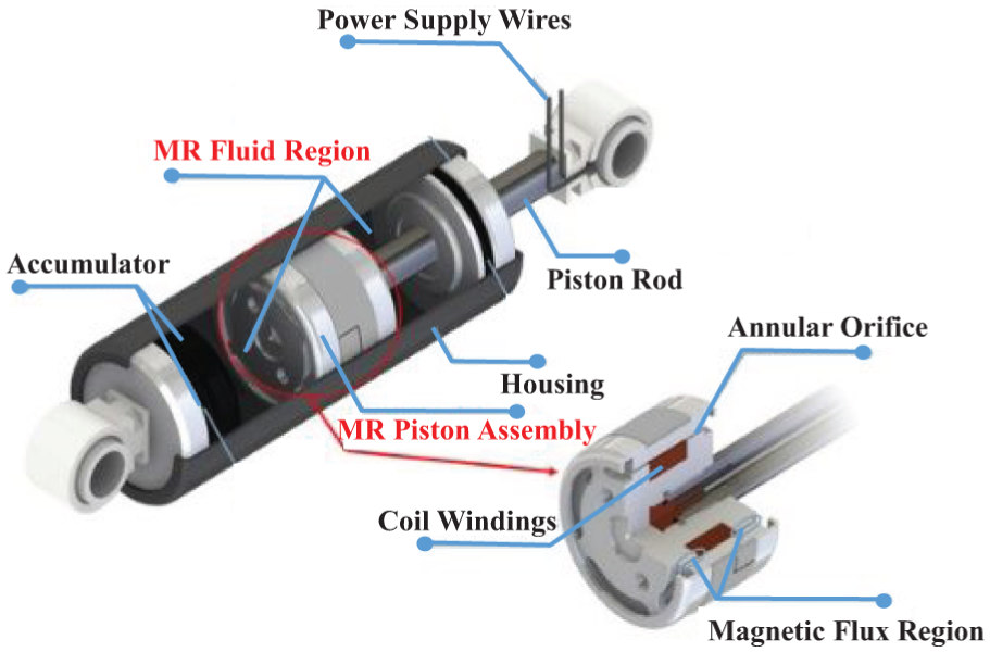
Schematic model of MR dampers (Şahin et al., 2010).
Types of MR damper faults
To examine the influence of potential faults in MR dampers used in structural control systems, the first step is to identify the possible fault types. Fault models can then be developed based on experimental evidence reported in the literature. This section summarizes the potential fault types in MR dampers, as documented in previous investigations in civil engineering, automotive, and aerospace applications, where they have been briefly addressed in previous studies. A crucial aspect of modeling MR damper faults is the accurate characterization of the damper’s dynamic behavior after a fault occurs. Accordingly, this section highlights the changes in dynamic behavior reported in experimental studies. For the purpose of accurate fault modeling, only cases supported by reliable experimental data are considered in detail and incorporated into the fault model development process.
Oil leakage
One of the most common faults in MR dampers is oil leakage from the cylinder. Such leakage can result from factors including improper installation, prolonged operation, external damage, or improper control system design. The primary consequence of oil leakage is a reduction in damping force, which is generally proportional to the amount of fluid lost. As MR dampers belong to the class of viscous dampers, their force generation mechanism relies on fluid flow through the piston. When fluid leakage occurs, the resulting loss of fluid volume leads to a decrease in the generated force. Experimental studies have confirmed this phenomenon, with the reduction in damping force being more pronounced at higher velocities (Tudón-Martínez and Morales-Menendez, 2015).
Magnetic particles trapped in the gap
Another common fault in MR dampers is the entrapment of magnetic particles within the piston-head region. Under prolonged loading and repeated operation, particles in the magnetorheological fluid tend to agglomerate and become trapped in this region. The resulting accumulation of particles hinders fluid flow through the orifices, which increases the damping force at high velocities. In contrast, at low relative velocities between the damper ends—corresponding to lower piston velocities—the magnetorheological fluid flows more easily through the accumulated particles, leading to a smaller rise in the damper’s output force compared to high-velocity conditions, where a larger fluid volume must pass through the piston-head region (Utami et al., 2018).
Clumping effect and orifice clogging
Agglomeration of magnetic particles may occur under prolonged exposure to strong magnetic fields, resulting in the formation of discrete, cluster-like structures. This phenomenon leads to non-uniform force distribution during cyclic operation. The primary mechanism responsible for particle adhesion and cluster formation is the residual magnetization retained in the particles, which promotes mutual attraction and aggregation. Consequently, particles in the MR fluid aggregate into larger clusters, hindering their passage through the piston-head orifices.
During damper operation, the MR fluid flows between the chambers through the piston head, carrying the agglomerated particles toward the orifices. After a certain piston displacement, these clusters may accumulate at the orifice entrances, potentially causing partial or complete blockage. This functional degradation becomes particularly significant at larger damper displacements, impeding fluid transfer between chambers and leading to an increase in the damper’s output force (Kumar et al., 2019).
Hard cake phenomenon
When the density of the particles exceeds that of the carrier fluid, suspended particles begin to settle. Moreover, once the magnetic field is removed, the particles do not properly redistribute, which accelerates their settling rate in the fluid. Over time, accumulated particles at the bottom of the cylinder agglomerate into a dense layer known as a hard cake. Numerous studies have addressed strategies to mitigate sedimentation in MR dampers. The influence of the hard-cake phenomenon on damper performance can be summarized as follows (Feng et al., 2015; Park and Park, 2001; Wahid et al., 2016):
The reduction in the concentration of magnetic particles within the viscous fluid reduces their effectiveness in modifying the fluid behavior under a magnetic field.
As the number of active magnetic particles decreases, the damping force decreases before the piston reaches the hard cake.
The formation of a dense layer at the cylinder bottom restricts the piston motion and leads to an increase in force generation at large displacements.
Separation of fluid particles
Particle separation in MR fluid refers to the separation between the liquid carrier phase and suspended solid particles under applied pressure, which leads to a reduction in the compressive force generated by the damper. This phenomenon has been experimentally investigated by Ismail and Aqida (2014), Ismail et al. (2012), Wahid et al. (2016) using cyclic compression tests. Their results demonstrated that the application of pressure loads fragmented the particle chains. If this functional defect occurs in an MR damper, the compressive force generated by the device is consequently diminished (Ismail et al., 2012; Ismail and Aqida, 2014; Wahid et al., 2016).
Oxidation of magnetic particles
Magnetic particles face several inherent challenges in magnetic fluid technologies. When exposed to air or elevated temperatures, oxidation may occur, reducing their magnetic strength. In addition, the carrier fluid may also accelerate oxidation. Particle oxidation not only increases the volume fraction of the solid phase but also increases the off-state viscosity of the MR fluid, potentially leading to damper malfunction. Furthermore, oxidation can induce chemical changes in iron particles, which degrade the performance of magnetic fluids. Interactions among fine particles may also generate colloidal forces, further affecting the stability of the suspension.
If such a functional fault develops in an MR damper, the off-state force becomes higher than the value predicted by the control system. Conversely, when a high voltage is applied by the controller, the damper produces a lower-than-expected force. Consequently, dampers affected by oxidation cannot perform effectively under either strong or weak seismic excitations (Wahid et al., 2016).
Erosion of magnetic particles
Magnetic particle erosion is another potential fault in MR dampers, in which suspended particles undergo structural degradation due to a sudden friction or mechanical shock. This erosion decreases the stability of the particles within the carrier fluid and enhances the likelihood of sedimentation, ultimately leading to a reduction in damper performance (Ashtiani et al., 2015).
Interior wall erosion
Another source of functional faults is the erosion of the inner walls of the cylinder caused by piston motion or interactions with magnetic particles. The use of anti-friction materials has been proposed as an effective approach to mitigate erosion effects and improve the durability of the damper (Foister et al., 2002; Kumar et al., 2019; Kumbhar et al., 2015).
Interior wall incrustation
Over time, a solid crust may develop on the inner walls of the cylinder. This phenomenon is primarily attributed to the particle agglomeration and their subsequent adhesion to the wall surface. As this crust hardens, it adversely affects the damper performance, ultimately preventing proper damper operation (Kumar et al., 2019).
Temperature change effects
Although MR dampers generally maintain stable performance over a wide temperature range, excessive temperature increases can alter the viscosity of the fluid, leading to deviations in the damper performance (Kumar et al., 2019).
Disturbance in the electricity current
The application of an electric current induces a semi-active state in the damper through the formation of a magnetic field. When the input current is set to either zero or to its maximum value, the MR damper operates as a passive device in the so-called passive-off and passive-on control modes, respectively. Under these conditions, commands from the control system have no influence on the force generated by the damper. Effectively, the MR damper behaves as a conventional viscous damper under these conditions (Dyke et al., 1996).
Time delay in transmitting signals and applying current
Delays in signal transmission and the application of electric current to the MR damper, arising from faults in the control system’s signal transmitters or current drivers, constitute additional uncertainties that must be considered in structural control systems. Given the rapid variations in earthquake ground motion during an earthquake, any delay in damper response can significantly compromise the structural performance. Under such conditions, the damper may generate insufficient force when a large force is required, or excessive force when a small force is needed, resulting in improper force application at critical moments (Kumar et al., 2019).
Table 1 summarize the main causes of the all described faults, their principal effects on the damper’s dynamic behavior, and the availability of reliable experimental evidence.
Summary of possible faults in MR Dampers.
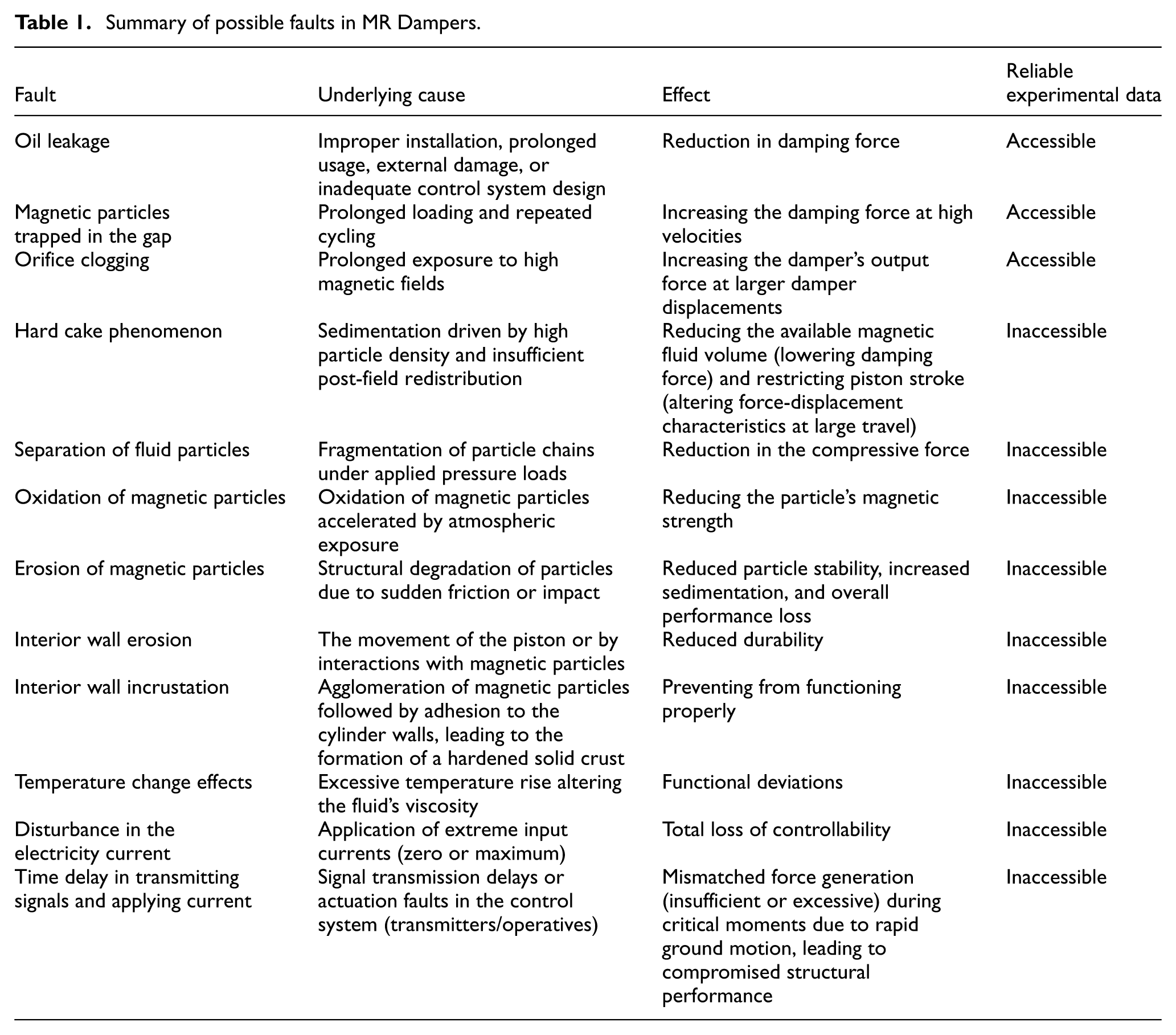
As noted earlier in this section, accurate modeling of faults in MR dampers requires experimental data that reflect the dynamic behavior of dampers under specific fault conditions. This modeling approach is grounded in prior experimental studies, providing a reliable basis for characterization. Based on an extensive review of the literature in civil, mechanical, and aerospace engineering—fields where MR dampers are most widely applied—experimental data have been obtained from well-established studies for three specific fault types: oil leakage, magnetic particles trapped in the gap, and orifice clogging. The high probability of underlying mechanisms cited for these three defects has established them as common faults in MR dampers (Tudón-Martínez and Morales-Menendez, 2015; Utami et al., 2018). Notably, oil leakage is easily detectable in the field via visual inspection, confirmed by the presence of oil drips surrounding the device. Trapped particles in the gap and Orifice clogging are difficult to detect via visual inspection in the field due to their location inside the mechanism. However, they can be diagnosed through non-destructive testing by analyzing the hysteresis loop. The first scenario results in an unusual increase in force at high velocities and near zero displacement in the force-displacement hysteresis loop. In contrast, the second scenario precipitates a sudden and disproportionate force increase at large displacements. Accordingly, as discussed in the following sections, the present analysis is limited to these three faults. Owing to the relatively limited use of semi-active control systems and the scarcity of experimental investigations addressing other fault conditions, other fault types have not been sufficiently investigated in previous research and fall outside the scope of this study.
Modified Bouc-Wen mechanical model
To effectively model the effects of the aforementioned mechanical faults on MR dampers, it is first essential to establish baseline models representing intact devices. MR dampers inherently exhibit nonlinear behavior and can reproduce a range of viscous damping characteristics through variations in the applied electrical current (Dyke et al., 1996).
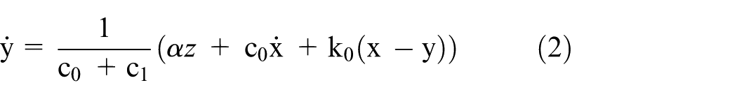
Among the various mechanical models developed for MR dampers, the Modified Bouc-Wen model is widely employed due to its capability to provide accurate and flexible representations of damper behavior under diverse operating conditions (Dyke et al., 1996; Wahid et al., 2016). In this study, this model forms the basis for analyzing the dynamic response of MR dampers, both in their intact state and when affected by mechanical faults. Within this framework, the output force is computed according to equation (1) (Lv et al., 2021; Wahid et al., 2016):
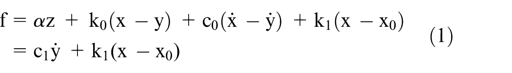
The parameters in equation (1) are defined as:


where
Figure 2 illustrates the mechanical model of the MR damper discussed above, which was originally proposed by Spencer et al., along with a comparison between the simulated model output and experimental results, highlighting the model’s high accuracy and fidelity (Spencer et al., 1997). Each fault in an MR damper induces functional changes, altering its dynamic response characteristics. The magnitude of these changes, however, is dependent on the severity and type of the fault.
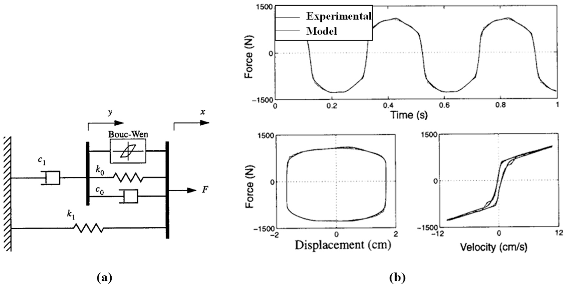
Modified Bouc-Wen model: (a) mechanical model, and (b) comparison between model output and experimental results (Spencer et al., 1997).
To numerically model faults in MR dampers, the parameters of the Modified Bouc-Wen model should be adjusted so that the resulting dynamic response closely replicates that of a faulty device. Each parameter in the numerical model corresponds to a specific aspect of the damper’s dynamic behavior and influences it in a distinct manner. Consequently, by appropriately tuning one or more parameters of the Modified Bouc-Wen model, a representative numerical model of a faulty MR damper can be developed.
The identification of the required parameter modifications in the Modified Bouc-Wen model, required to accurately represent a faulty MR damper, is based on the observed variation ratios in key dynamic characteristics. These characteristics include the force generation capacity, primary and secondary damping components, as well as the overall trends and shapes of the force–displacement and force–velocity curves. This information is extracted from experimental data, and the parameters of the Modified Bouc-Wen model are systematically adjusted to reproduce these observed changes in the numerical simulation.
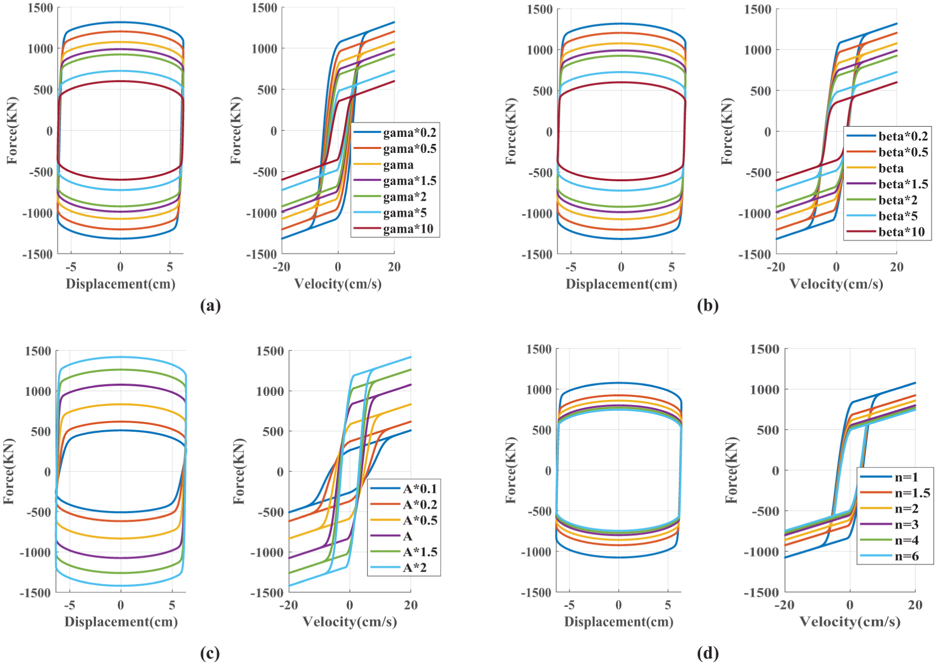
Effects of Modified Bouc-Wen model parameters
Each parameter of the Modified Bouc-Wen model influences specific aspects of the MR damper’s dynamic behavior. A clear understanding of these influences is essential for accurately simulating the effects of mechanical faults. To illustrate the sensitivity of the model to parameter variations, a 100-ton MR damper is modeled. The parameters of the 100-ton damper are summarized in Table 2 (Jung et al., 2003; Shirgir et al., 2021; Spencer et al., 1998; Talatahari et al., 2012) and the applied voltage is assumed to be limited to 10 V. Selected parameters are systematically scaled by coefficients greater than and less than one, while keeping other conditions constant, allowing the assessment of how increases or decreases in each parameter affect the damper’s dynamic response.
Parameter
Parameter α: An increase in parameter α results in a higher output force, demonstrating a direct relationship between the two. However, variations in α exert only a minor influence on the damper stiffness, reflected by the slope of the force–displacement curve. In the force–velocity response, changes in α primarily affect the low-velocity slope (initial viscosity), while having no impact on the high-velocity slope or the gap between the curve branches, which remains nearly constant. Figure 3(b) illustrates how variations in α impact the dynamic response of the MR damper.
Parameter
Parameters
Parameters
The parameters of the considered MR damper (Jung et al., 2003; Shirgir et al., 2021; Talatahari et al., 2012).
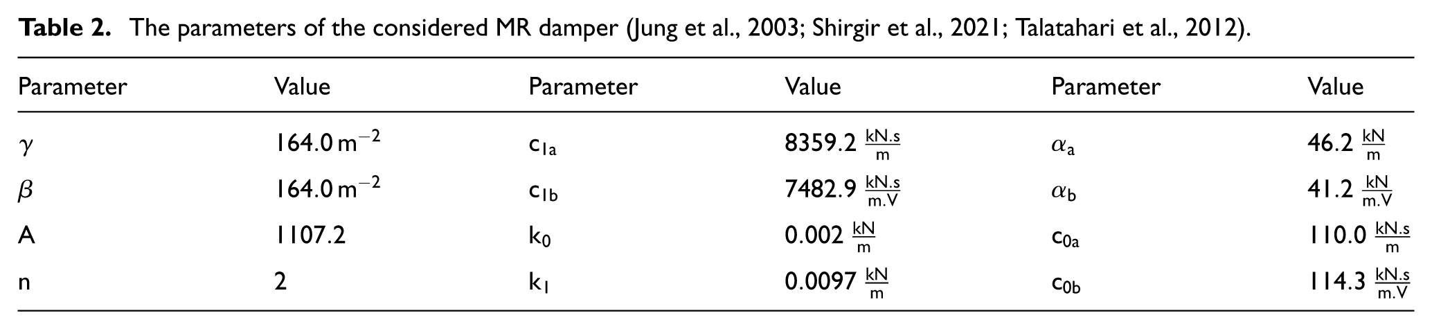
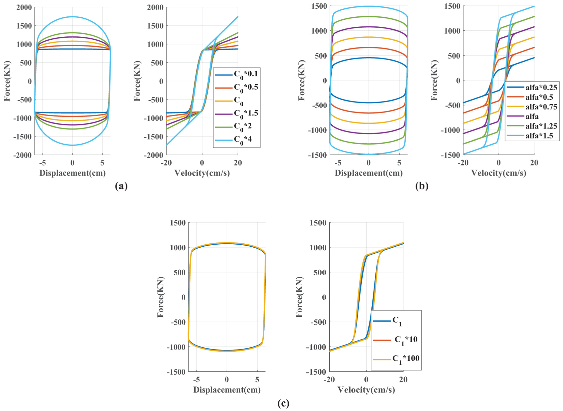
Dynamic behavior loops of MR dampers at different values of: (a)
Dynamic behavior loops of MR dampers at different values of: (a)
Modeling operational fault
As previously highlighted, the availability of experimental data concerning MR damper faults remains limited. However, reliable modeling and validation of the influence of such faults on the damper’s dynamic behavior, require sufficient experimental evidence. Owing to this limitation, the present study focuses on only three specific types of defects:
oil leakage,
trapped particles, and
orifice clogging.
Modeling oil leakage
In 2015, Tudón-Martínez and Morales-Menendez investigated the effects of oil leakage on an MR damper used in an automotive shock absorber. They examined how oil leakage influences the force–velocity and force–displacement characteristics under dynamic loading conditions. As shown in Figure 5, the responses of a healthy damper (black points) and dampers subjected to 5% (red points) and 10% (blue points) oil leakage, referred to as fault 1 and fault 2, respectively, are presented (Tudón-Martínez and Morales-Menendez, 2015).
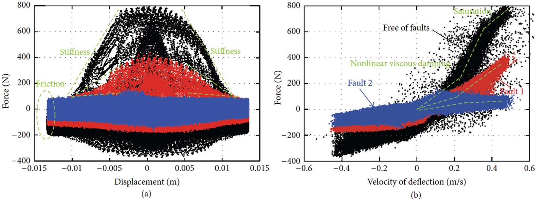
Experimental characteristic curves of a healthy damper (black points) and, dampers subject to 5% (red points), and 10% (blue points) oil leakage, referred to as fault 1 and fault 2, respectively: (a) force-displacement, and (b) force-velocity diagrams (Tudón-Martínez and Morales-Menendez, 2015).
As shown in Figure 5, both the force capacity of the damper and the damping coefficient decrease in the event of oil leakage. This phenomenon leads to a reduction in both primary and secondary damping, along with a notable decline in the overall force generated by the damper. It should be noted that the data presented in Figure 5 were not obtained under a controlled loading cycle; rather, they were collected from the motion of a vehicle traveling over a road surface (Tudón-Martínez and Morales-Menendez, 2015). Therefore, for the purpose of modeling the defect, the envelope of the experimental data and the average values reported in that study are utilized.
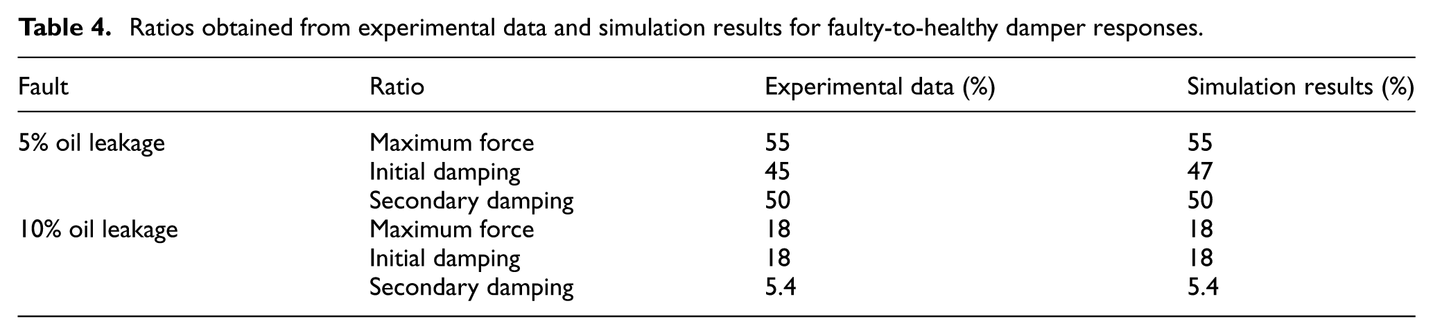
The damper used in this experimental study (Tudón-Martínez and Morales-Menendez, 2015) has a lower capacity than the 100-ton MR damper. Nevertheless, several studies have employed scaled experimental data to represent dampers with different capacities (Yang et al., 2002, 2020, 2021), a similar proportional approach is adopted for modeling damper faults. Specifically, the effects of damage observed in the lower-capacity damper can be extrapolated to the 100-ton damper investigated in this research. To achieve this, the maximum force and damping of the damper under 5% and 10% oil leakage conditions are determined relative to the healthy state based on experimental results, and the same ratios are then applied to the 100-ton MR damper to model the damaged configurations with oil leakage. These ratios are presented in Table 4, where the force–velocity curve is approximated using a bilinear model, and the slope of each segment represents the primary or secondary viscosity.
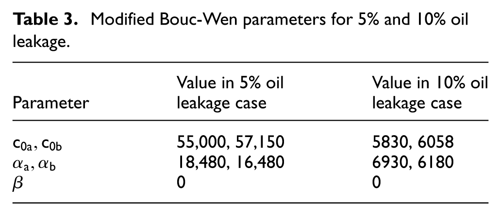
Based on the identified influence of each Modified Bouc-Wen parameter on the dynamic behavior and considering the observed effects of oil leakage, it is evident that accurately modeling this defect requires adjustments to three key parameters:
Modified Bouc-Wen parameters for 5% and 10% oil leakage.
The simulation results for two oil leakage levels, 5% and 10%, are illustrated in Figure 6, which shows the corresponding changes in the dynamic behavior of the damper. As seen in this figure, the simulated response of the faulty damper closely reproduces the experimental observations. Furthermore, the last column of Table 4 presents the mentioned ratios calculated from the simulation results, which are used to assess the accuracy and reliability of the proposed model for the damaged damper. As indicated in the table, these key ratios match the experimental data in all cases, except for the initial damping under the 5% oil leakage condition, where the discrepancy is only approximately 4.5%. Overall, Figure 6 and Table 4 confirm that the proposed faulty damper model can accurately reproduce the behavior of the damaged damper.
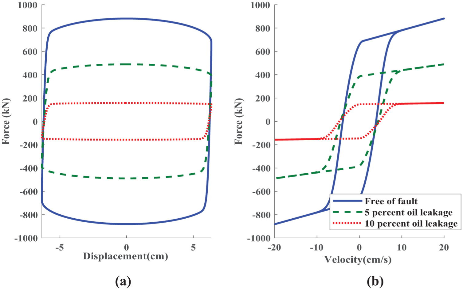
MR damper responses under three conditions, intact, 5% oil leakage, and 10% oil leakage: (a) force-displacement, and (b) force-velocity diagrams.
Ratios obtained from experimental data and simulation results for faulty-to-healthy damper responses.
Modeling particle trapping
As described earlier, the particles within the magnetic fluid can become trapped in the piston head after prolonged cyclic loading. To investigate the effects of this phenomenon, Utami et al. conducted experimental tests on an MR damper subjected to between 1000 and 170,000 loading cycles (Utami et al., 2018). The force-displacement curves shown in Figure 7 correspond to different loading cycles and show a clear increase in force with the number of cycles. It should be noted that in all recorded cycles, a slight indentation appears at the onset of direction reversal in the damper motion. However, since this feature is also observed in the initial cycles of the undamaged damper, it is not considered indicative of a defect and is therefore excluded from defect modeling process. Consequently, in the simulation of this defect, only the increase in force associated with trapped magnetic particles is taken into account.
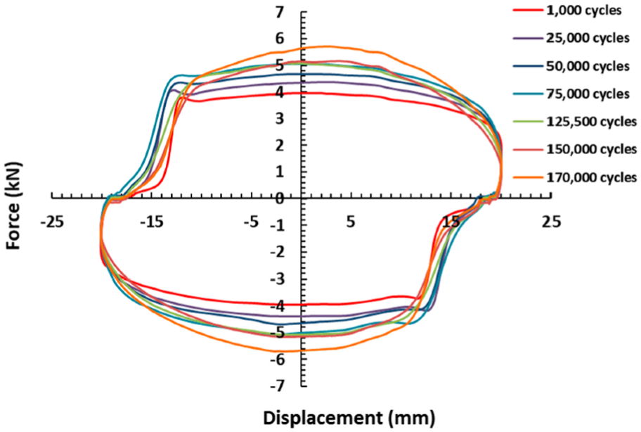
Force-displacement behavior of the MR damper for loading cycles up to 170,000 (Utami et al., 2018).
Figure 8 illustrates the variation of the damper’s maximum force as a function of the loading cycles. According to the experimental data reported by Utami et al., after 130,000 loading cycles, the maximum generated force increased by about 30% compared with that at 1000 cycles (Utami et al., 2018). It is also evident from the results that beyond 80,000 cycles, the maximum damping force remains nearly constant. Therefore, in modeling this defect, a 30% increase in the damper’s peak force can be considered a representative adjustment. These findings highlight the significant influence of magnetic particle trapping on the long-term performance and dynamic behavior of the MR damper.
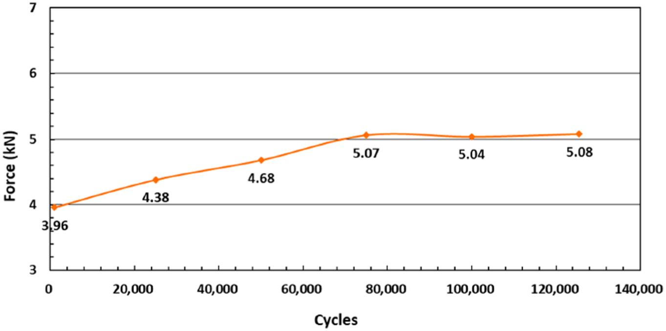
Maximum damping force of the MR damper at different loading cycles (Utami et al., 2018).
In buildings located in seismic zones or subjected to continuous vibrations, this fault may gradually develop in the dampers installed in the structure. To model the effect of particle trapping, which aligns with the experimental observations, the obtained curves are fitted to the Bouc–Wen model. As shown in Figure 7, the increase in the maximum damper force is attributed to the upward curvature of the force–displacement curve. At higher loading cycles, both the curvature and the elevation of the curve become more pronounced. This behavior is associated with the damper’s viscosity at high velocities (Dyke et al., 1996).
This change in the modified Bouc–Wen model is associated with the parameter
The values of parameters
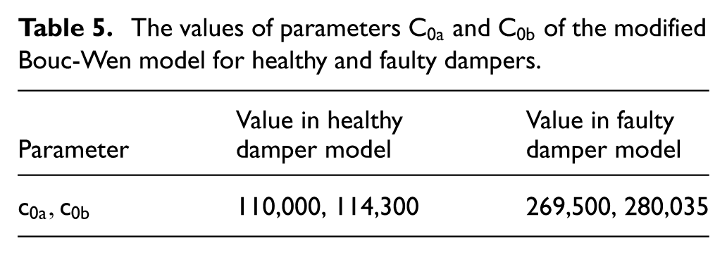
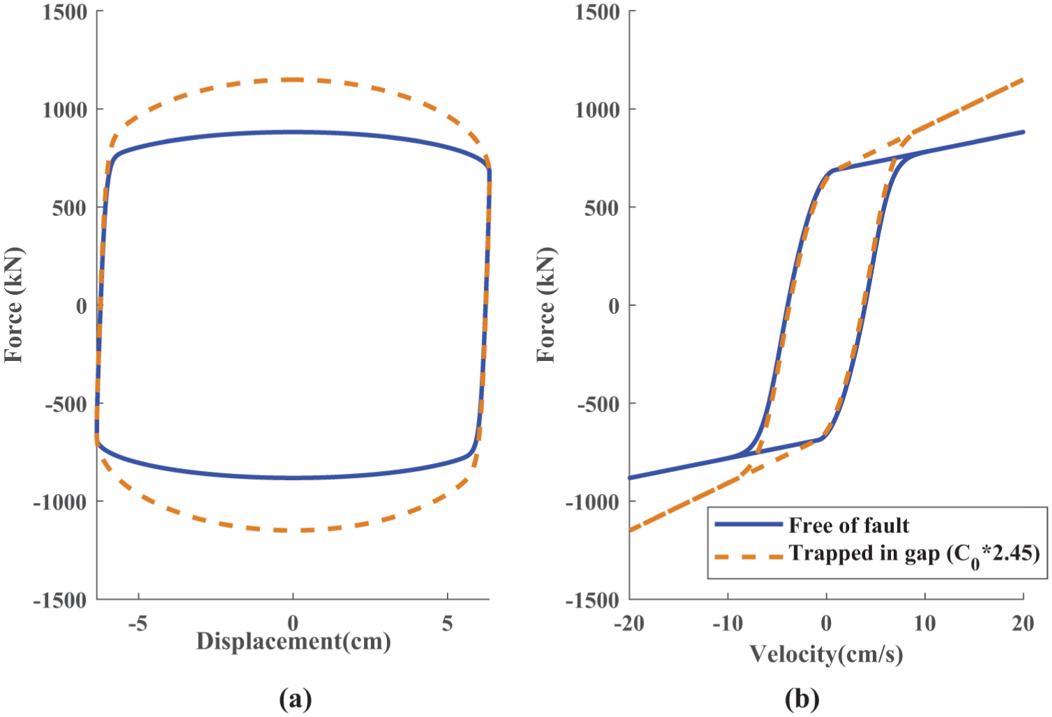
Dynamic model of healthy and faulty damper (particle trapped in the gap): (a) force-displacement, and (b) force-velocity diagrams.
Modeling orifice clogging
A study by Wang et al. provides valuable insights into the effects of orifice clogging defects (Wang et al., 2019). In their research, experimental tests were carried out on 30 dampers installed on the Dongting Lake Bridge that had been replaced after 10 years of service to assess their mechanical behavior under long-term service. The force-displacement and force-velocity responses of these dampers are presented in Figure 10. These figures compare the performance of the investigated dampers with that of a newly installed one.
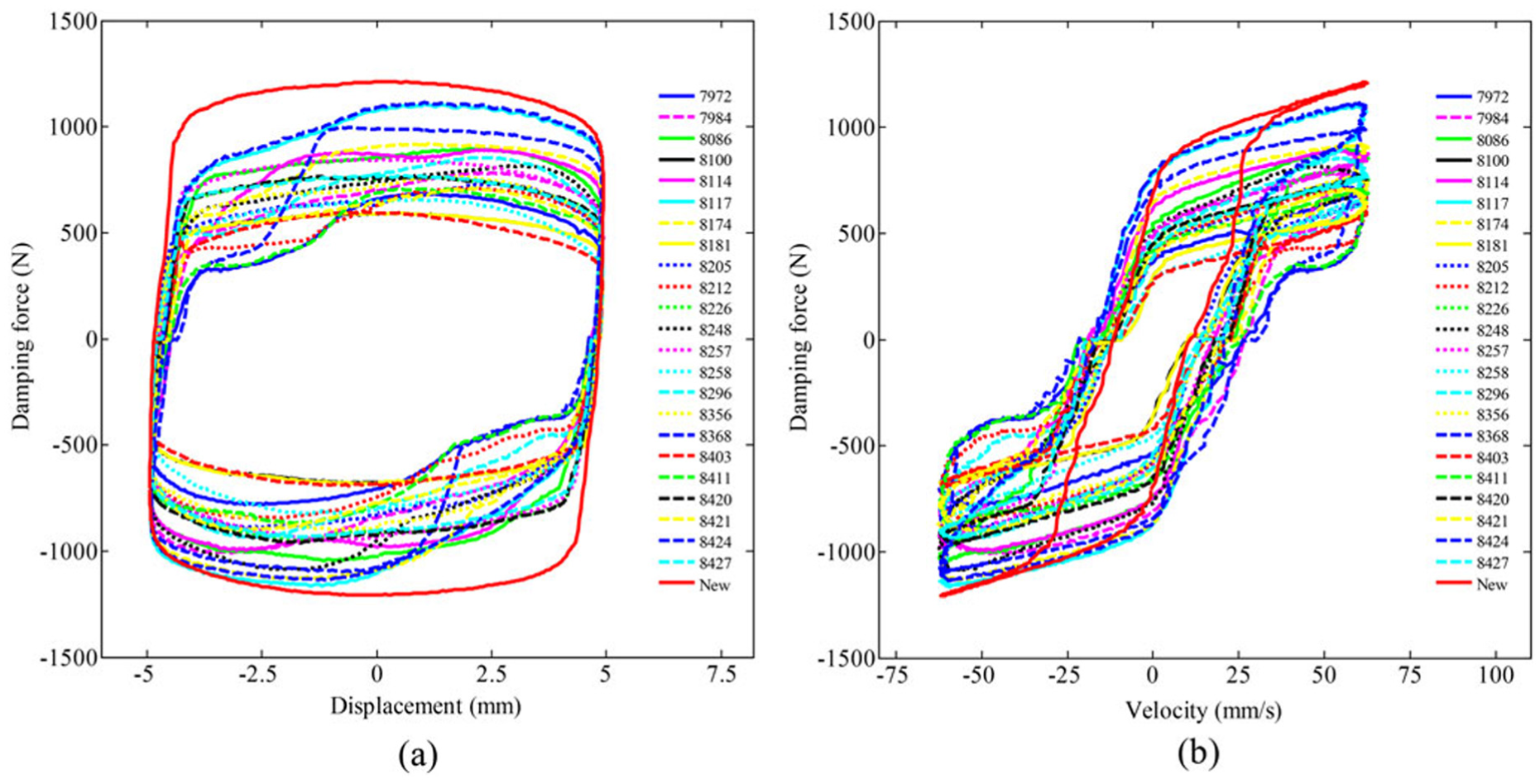
Hysteretic behavior of dampers in Dongting Lake Bridge: (a) force-displacement, and (b) force-velocity diagrams (Wang et al., 2019).
Notably, the tested dampers exhibit a relative reduction in force output compared to the healthy damper, which can be attributed to oil leakage. This assumption is supported by the observed reduction ratios, which are consistent with findings from previous studies. The existence of this fault was further verified through complete disassembly of the dampers, revealing a significant loss of oil.
If the effects of oil leakage and the associated reduction in damper force are neglected in modeling the orifice clogging failure, the main characteristic that can be attributed to orifice clogging in these diagrams is the dip observed in the force–displacement curve at the onset of the return stroke. At the beginning of the damper’s return stroke, the generated force behaves similarly to that of a healthy damper. However, as the motion continues and orifice clogging gradually develops, the damper force increases, producing a noticeable dip in the force–displacement curve. This phenomenon is also reflected in the force–velocity diagrams, where the two branches of the curve separate at higher damper velocities. As shown in Figure 10, when the direction of motion changes (
The Bouc–Wen model must be modified so that its output accurately reflects the observed behavior. To simulate this type of fault, the maximum damper force is first increased and then reduced at the onset of motion reversal. On average, a 50% increase in the generated force was observed due to this fault. Accordingly, to replicate this behavior, the total force produced by the damper is initially increased by 50%, meaning that the damper force is multiplied by 1.5. This adjustment simulates the damaged state of the damper. Then, at the beginning of the damper’s motion reversal, the force is reduced using the reduction factor
Equations (8) and (9) are used to model the orifice clogging defect for a 100-ton damper. The optimal value of
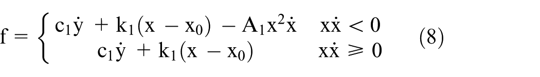

Figure 11 shows the force-displacement and force-velocity curves obtained using equation (8), which represents the orifice clogging defect. Compared with Figure 10, the results show good agreement between the model predictions and the experimental data. As illustrated in the figure, the damper initially exhibits force characteristics comparable to those of a healthy damper during the return stroke. As the motion progresses and orifice clogging gradually intensifies, the damping force rises by nearly 50%. This agreement further confirms the effectiveness of the model in simulating the orifice clogging defect.
Dynamic model of healthy and faulty damper (orifice clogging): (a) force-displacement, and (b) force-velocity diagrams.
Since the experimental results used as the basis for developing the faulty MR damper model were not obtained under ideal laboratory conditions, a calibration procedure is required in order to enable a reliable comparison between the experimental results and the modeling results. For calibration, the Modified Bouc–Wen model of a healthy 100-ton MR damper, which has been widely accepted in the literature for simulating the behavior of MR dampers (Jung et al., 2003; Shirgir et al., 2021; Spencer et al., 1998; Talatahari et al., 2012), is implemented over the displacement range corresponding to the healthy damper in the experimental results. Subsequently, the parameters a and b are determined using linear regression of the form
For example, the calibration parameters a and b for the oil leakage experiment are obtained as 1651.75 and −281.83, respectively and For the 5% and 10% oil leakage faults, RMSE and R2 are obtained as (19.71, 0.89) and (2.9, 0.88), respectively. The experimental results corresponding to the other two faults are also prepared using the same procedure, and the RMSE and R2 values are calculated for them. For the particle-trapped and orifice clogging faults, these values are (29.42, 0.87) and (31.08, 0.88), respectively. It can be observed that the RMSE for all modeled faults is less than 5% of the maximum damper output, indicating that the proposed model estimates the experimental results with excellent accuracy. The obtained R2 values also fall within a good and acceptable range.
Effects of damper fault on controlled structures
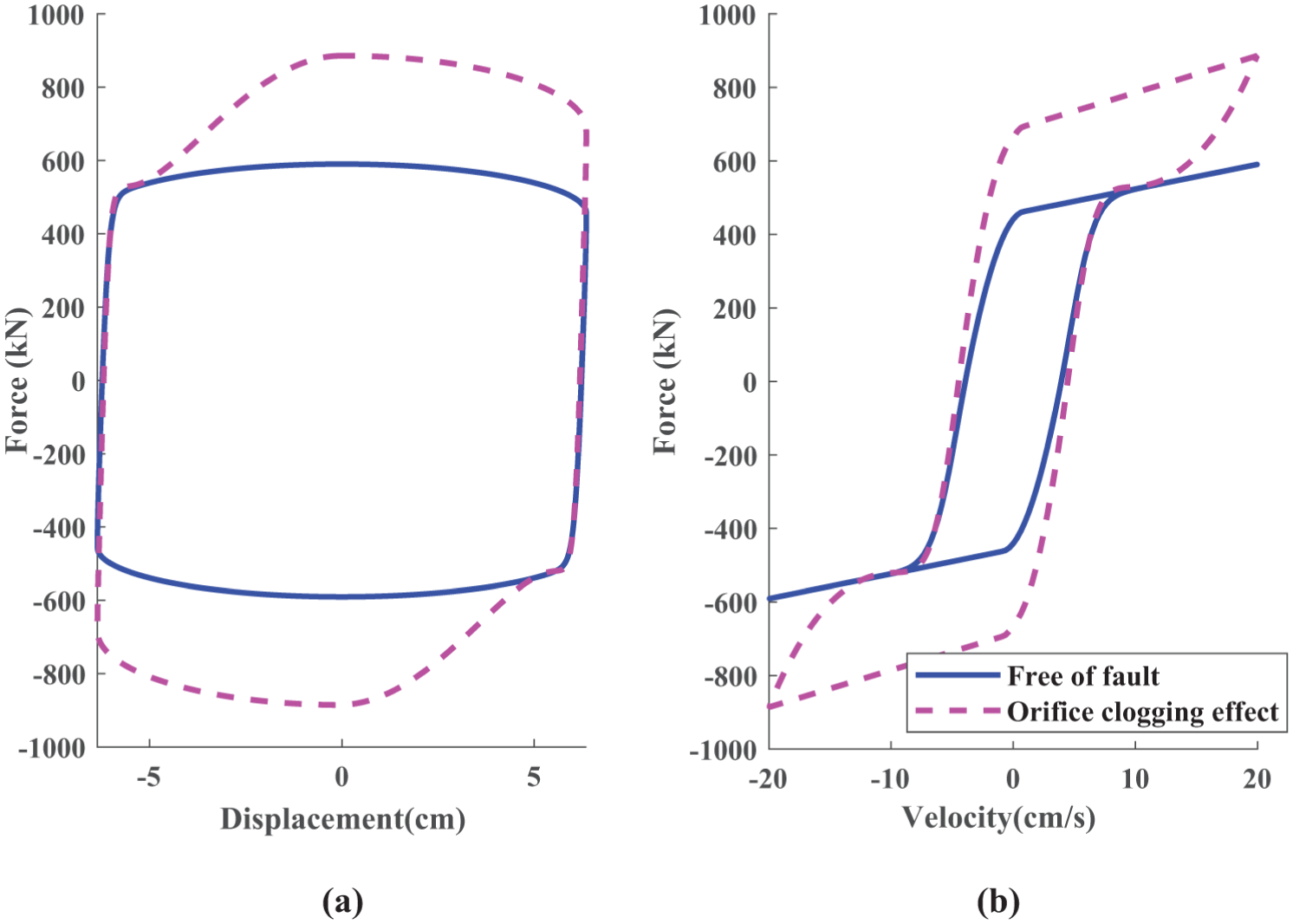
To assess the impact of faulty dampers on the seismic performance of controlled structures, a 20-story benchmark building is considered. The characteristics of the building elements, their connections, the arrangement of dampers, and structural materials are thoroughly described in the reference article (Spencer et al., 1998). In this study, the same specifications and modeling approach reported in the reference are adopted. The dynamic behavior of the structure is analyzed under various fault scenarios in the MR dampers installed on its 1st, 3rd, 5th, 7th, 10th, 13th, 16th, and 19th stories. The MR dampers used in the benchmark model are 100-ton dampers, the characteristics of which are listed in Table 2 (Jung et al., 2003; Shirgir et al., 2021; Talatahari et al., 2012). The arrangement of the MR dampers within the structure is illustrated in Figure 12.
Arrangement of MR dampers on the 20-story benchmark structure.
To evaluate the impact of damper faults on structural behavior, two different control algorithms were employed in separate cases: the SACM (Bitaraf and Hurlebaus, 2013) and LQG controllers (Bhowmik and Debnath, 2024; Chaudhuri et al., 2022). The SACM control strategy continuously adjusts its parameters online to minimize the error between the actual system response and a predefined reference response. This method is particularly effective for systems characterized by uncertainties or limited dynamic information. The objective of the proposed algorithm is to ensure that the output of the control system (
Here, the weight matrices for the LQG controller are chosen as
The dynamic behavior of controlled structure is written as:


where


where

where


The adaptive gain vector,


where
The structural responses are evaluated using three different earthquake records: Kobe (1995), El Centro (1940), and Northridge (1994) (Spencer et al., 1998). These ground motions represent diverse seismic scenarios, allowing the examination of how damper faults influence structural behavior under different earthquake conditions.
Figure 13 shows the block diagram of the controlled benchmark structure used in this study. The control algorithm block receives the ground motion input, the structural response, and the previously generated damper force as inputs. Depending on the selected control algorithm (either SACM or LQG), this block computes the required input voltage for the MR damper. This calculated voltage, together with the damper velocity, is then transmitted to the MR damper model block, where the corresponding damper force is calculated using the modified Bouc–Wen model. In this block, the numerical model of the healthy damper is replaced by the faulty damper model. With this change, the control force is computed based on the described defect rules.
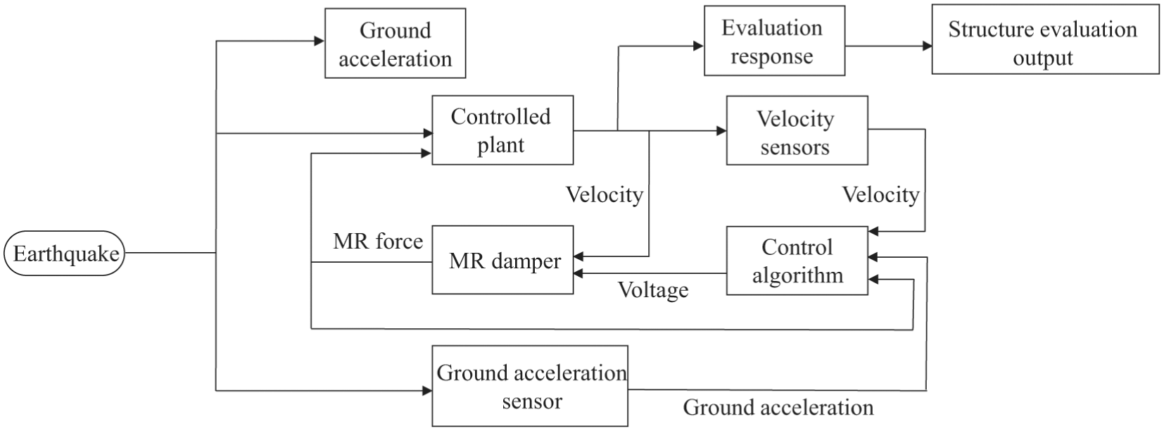
Block diagram of the proposed approach.
In the case of a faulty damper, the control algorithm remains unchanged and continues to compute the input voltage under the assumption that the damper is functioning normally. However, when this voltage is applied to the faulty damper, the generated force—based on the altered parameters of the damaged damper model—deviates from the expected output. This discrepancy ultimately degrades the overall performance of the control system.
Effect of oil leakage on seismic responses
To evaluate the impact of the modeled defects on the response of a structure equipped with MR dampers, the effect of 5% oil leakage was examined. Figure 14 indicates that, for both the SACM and LQG algorithms, the discrepancy between the intact damper and the damper with 5% oil leakage increases as the damper force output increases. Since the LQG algorithm computes higher damper forces compared to the SACM algorithm, the difference between the forces generated by the faulty and intact dampers is more pronounced in LQG. This behavior can be attributed to the inability of the faulty damper to produce large forces.
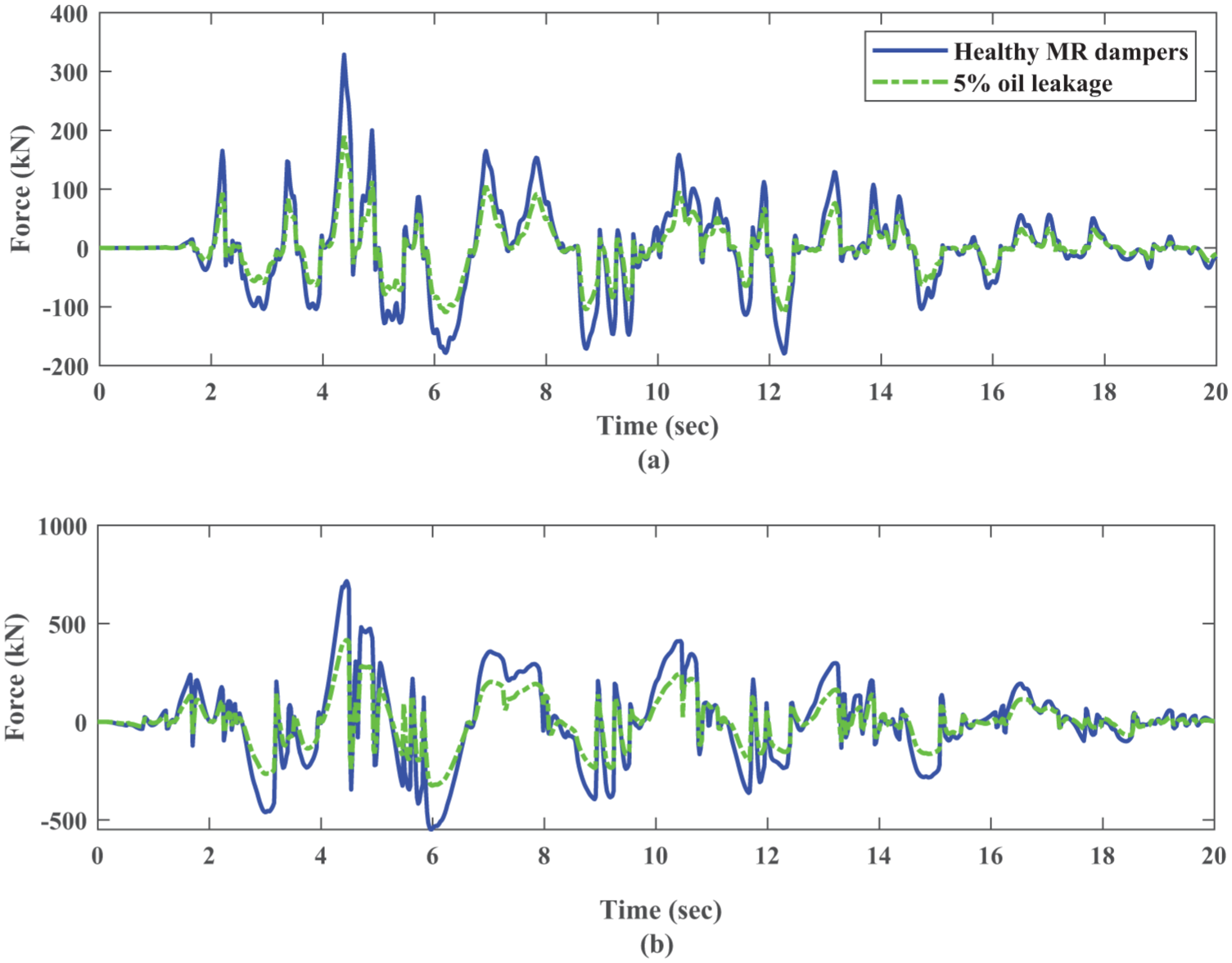
Comparison of the damper force time histories on the 10th story between the healthy and faulty cases under El Centro earthquake with 5% oil leakage: (a) SACM algorithm, and (b) LQG algorithm.
Effect of particle trapping on seismic responses
As mentioned earlier, particle trapping within the gap increases the force generated by the damper at high velocity levels. For this type of fault, Figure 15 shows the time-history response of the damper force on the 10th floor, comparing faulty and intact dampers under the El Centro earthquake. It also compares the required control forces computed using the LQG and SACM algorithms. As shown, faulty dampers produce higher forces than required at the peak response points. It is observed that faulty dampers increase the generated force by up to 20%. This finding highlights that particle trapping defects can cause an unintended rise in damper force, which may adversely affect the structural response.
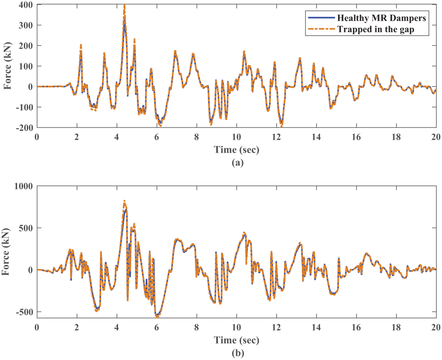
Comparison of the damper force time histories on the 10th story between the healthy and faulty cases under El Centro earthquake with particle trapping in the gap: (a) SACM algorithm, and (b) LQG algorithm.
Figure 16 presents a comparison of the maximum damper forces on each story for two scenarios: one with intact dampers and the other with dampers affected by particle trapping within the gap. This figure illustrates the maximum damper forces of the controlled structure by the SACM algorithm under two different ground motions. As observed, the forces in faulty dampers—and their deviations from the intact ones—tend to increase under ground motions with higher velocity content, such as the Kobe earthquake. Furthermore, when faulty dampers generate forces that deviate from the expected values, the controller appears to compensate for this deviation by reducing the required forces in the intact dampers located on other stories.
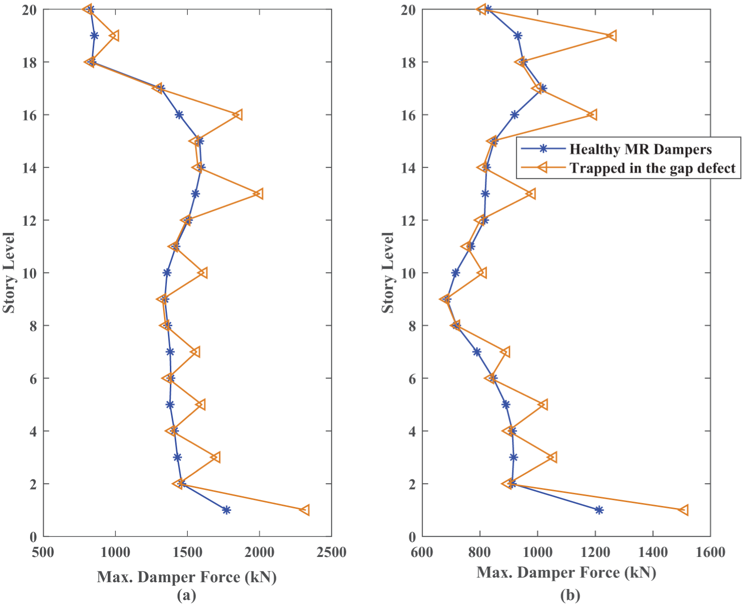
Comparison of the generated force of healthy and faulty dampers with particle trapping using the SACM controller under: (a) El Centro, and (b) Kobe ground motions.
Effect of orifice clogging on seismic responses
Figure 17 compares the time history of damper forces on the 10th story between healthy and faulty dampers affected by orifice clogging. It illustrates the control forces required to regulate the dynamic response of the structure subjected to the El Centro earthquake using either SACM or LQG control algorithms. As observed, the orifice clogging fault leads to an increase in the forces generated by the faulty dampers. Moreover, in the case of the LQG algorithm, the difference between the forces generated by healthy and faulty dampers is more pronounced compared with that observed under the SACM algorithm.
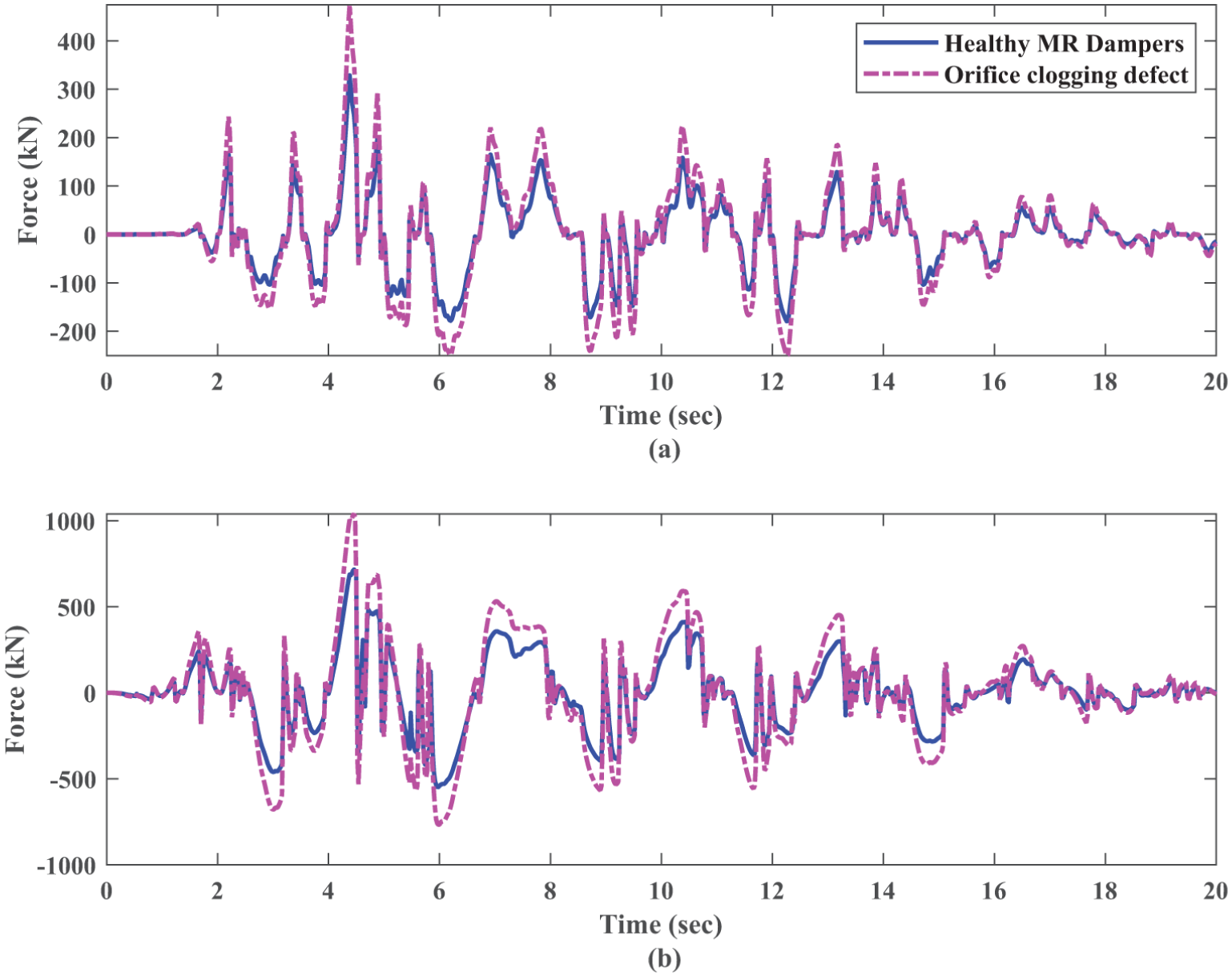
Comparison of the damper force time histories on the 10th story between the healthy and faulty cases under El Centro earthquake with orifice clogging: (a) SACM algorithm, and (b) LQG algorithm.
Figure 18 compares the maximum floor accelerations of the structure equipped with dampers affected by orifice clogging under three ground motions, using the SACM control algorithm, with those of the structure with intact dampers. As observed, for the Kobe and Northridge records, which exhibit higher floor accelerations, the orifice clogging fault has a more significant impact on the floor accelerations. Depending on the characteristics of the ground motion, this defect can increase the damping force by up to 50%.
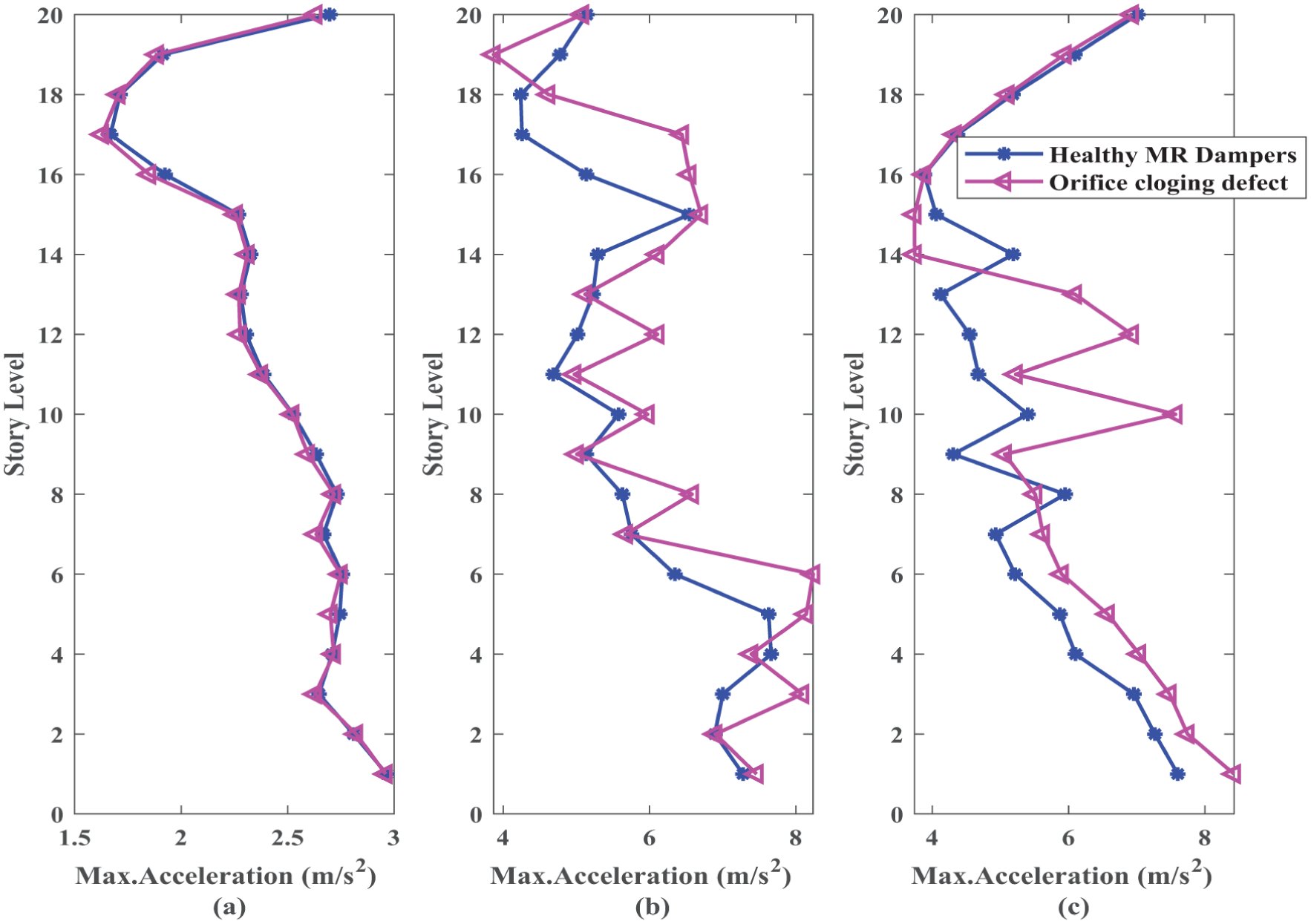
Comparison of the maximum floor acceleration of the building with healthy and faulty dampers (orifice clogging) under three ground motions when controlled by the SACM algorithm: (a) El Centro, (b) Kobe, and (c) Northridge.
Comparison of the effects of faulty dampers
To simultaneously examine the effects of three different damper defects, the maximum structural responses at each story levels—including drift ratio, relative velocity and floor acceleration—under the Kobe earthquake record using the SACM controller are compared in Figure 19. As shown, the maximum drift and relative velocity increase most significantly in the case of the 10% oil-leakage defect, whereas the orifice clogging defect leads to a reduction in the maximum drift and relative velocity compared with the intact damper. In the plot of maximum floor acceleration, no consistent trend is observed; however, for the orifice clogging defect, the maximum floor acceleration is higher than that resulting from the other damper defects.
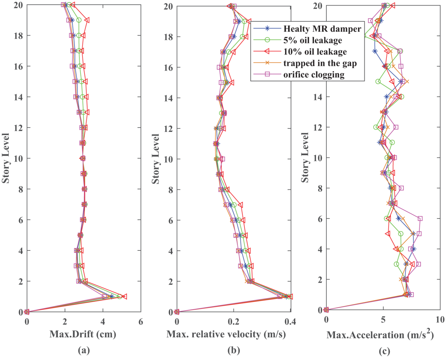
Comparison of the maximum response of the controlled building with healthy and different type of faulty dampers under Kobe ground motion when controlled by the SACM algorithm: (a) inter-story drift, (b) relative velocity, and (c) floor acceleration.
To facilitate a more comprehensive evaluation the impact of various damper defects on the behavior of the controlled structure, four performance criteria, denoted as j1, j2, j3, and j4, are employed. These criteria assess the effectiveness of the control system in controlling maximum horizontal displacement, relative velocities, floor accelerations, and base shear of the structure, respectively. The mathematical definitions of these criteria are provided in equations (19)–(22) (Spencer et al., 1998).
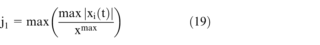
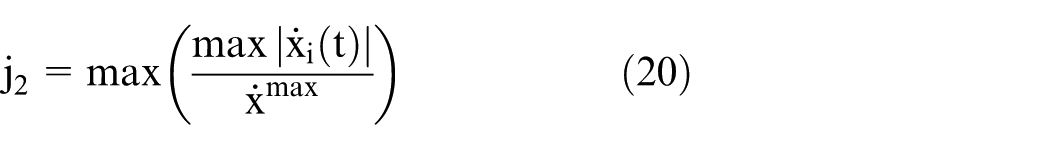
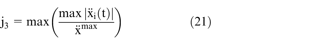
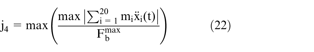
In these equations, the terms are defined as follows:
To investigate the effect of the location of faulty dampers within the structure, the faulty dampers are arranged in three different scenarios and the above performance indices are evaluated:
Scenario 1) faults in the dampers installed on the 1st, 3rd, 5th, 7th, 10th, 13th, 16th, and 19th stories
Scenario 2) faults in the dampers installed on stories 1–10
Scenario 3) faults in the dampers installed on stories 11–20
Table 6 presents the performance criteria under different fault scenarios for the Kobe earthquake record using the LQG controller. In all scenarios, the oil leakage faults result in the highest values of the performance indices j1, j2, and j4 compared with the particle trapping and orifice clogging faults. The J3 index does not exhibit a consistent trend. In the first two scenarios, higher J3 values are observed for the particle trapping and orifice clogging faults, whereas in the third scenario the oil leakage fault leads to a higher J3 value. These differences can be interpreted as follows:
It is well known that the area enclosed by the damper force–displacement hysteresis loop represents the amount of energy dissipated by the damper (Spencer et al., 1997). As shown in Figure 6, increasing the oil leakage ratio reduces the area of this loop, indicating a decrease in the energy dissipated by the damper. Consequently, more energy is stored in the structure, leading to larger vibration amplitudes. In contrast, Figures 9 and 11 show that in the presence of particle trapping and orifice clogging faults, the area enclosed by the force–displacement loop becomes larger than that of the healthy case, implying that the damper dissipates even more energy than in the designed condition.
Oil leakage reduces the maximum force generated by the damper, whereas particle trapping and orifice clogging undesirably increase it. Since the damper force acts as a resisting force that controls structural motion, a reduction in damper force makes the system behave similarly to a structure with lower effective damping, resulting in larger displacements. The increase in displacement also leads to higher stored potential energy at the turning points of motion. This energy is subsequently converted into kinetic energy as the structure returns toward its equilibrium position, thereby increasing structural velocities (Chopra, 2017; Symans and Constantinou, 1999). Moreover, because the base shear force is directly related to structural displacement, the larger displacements associated with oil leakage also lead to increased base shear forces (Chopra, 2017).
Comparison of performance criteria for MR dampers under different fault scenarios using the LQG control algorithm during the Kobe earthquake record.
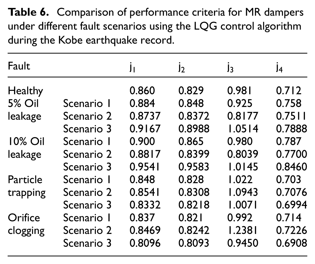
Moreover, the increase in the indices j1, j2, and j4 due to oil leakage becomes more pronounced when the faulty dampers are located on the higher stories. The J3 index does not exhibit a consistent trend. In the case of oil leakage, the J3 index becomes larger as the faulty dampers are located on the higher stories. In contrast, the increase in the J3 index associated with particle trapping and orifice clogging faults becomes more significant when the faulty dampers are positioned on the lower stories. The behavior can be explained by the distribution of structural responses along the height of the building. In tall buildings, larger displacements and velocities typically occur in the upper stories; therefore, MR dampers installed at higher levels play a more significant role in controlling these responses. When oil leakage occurs, the damping capacity of the damper is substantially reduced, which weakens the energy dissipation capability where the demand is highest. Consequently, the increases in the maximum displacement, velocity, and base shear responses become more pronounced when the faulty dampers are located in the upper stories.
Conclusions
This study aimed to provide a comprehensive evaluation of the potential adverse effects of different fault types in MR dampers on the seismic performance of controlled structures. The research included a detailed investigation of various damper defects, the numerical modeling and validation of three representative MR damper faults using available experimental data, and a sensitivity analysis to examine device performance under these fault conditions. Furthermore, the developed faulty damper models were implemented in a 20-story benchmark building to evaluate the seismic response under different ground motions and under various scenarios for the location of faulty dampers within the structure when the LQG or SACM control algorithms were employed. The proposed fault models offer a practical framework for systematically assessing how different faults influence control system performance. By explicitly capturing the impact of these faults, the models provide valuable insight that facilitates the design of more robust and fault-tolerant control strategies, ultimately helping to maintain reliable structural performance even when damper degradation occurs.
The important results obtained from this study are as follows:
(1) Oil leakage in MR dampers leads to a substantial reduction in their generated force capacity. Specifically, oil-leakage levels of 5% and 10% result in approximately 45% and 82% decreases, respectively, compared to the initial force capacity.
(2) The presence of trapped particles within the cylinder head chamber can increase the damping force by up to 30%, exceeding the target force predicted by the control algorithm.
(3) Orifice clogging, depending on the characteristics of the input ground motion, can increase the damper output force by nearly 50%.
(4) In all scenarios, the oil leakage faults result in the highest values of the performance indices j1, j2, and j4 compared with the particle trapping and orifice clogging faults. The J3 index does not show a consistent pattern. In the first two scenarios, the particle trapping and orifice clogging faults produce higher J3 values, while in the third scenario the oil leakage fault results in a larger J3 value.
(5) the rise in the performance indices j1, j2, and j4caused by oil leakage becomes more pronounced when the faulty dampers are placed in the upper stories. The J3 index does not follow a consistent trend. For the oil leakage fault, the J3 value increases when the faulty dampers are located on the higher stories. In contrast, for the particle trapping and orifice clogging faults, the increase in the J3 index becomes more pronounced when the faulty dampers are positioned on the lower stories.
(6) LQG is an optimal control algorithm fundamentally dependent on an accurate system model. Since oil leakage represents a predicable loss of force, The LQG controller preforms better because its inherent optimally allows it to compensate for this known, model-based error. However, SACM is an adaptive control method characterized by its strong robustness against system uncertainties. particle-trapping and orifice-clogging defects introduce unpredictable increases in force. The adaptive nature of SACM enables it to adjust its parameters to accommodate this non-linear and unpredictable change in system dynamics.
(7) The severity of the earthquake excitation significantly influenced the results—faulty dampers exhibited a more pronounced adverse impact during stronger seismic events, such as those represented by the Kobe earthquake record.
This study highlights the critical importance of accurately identifying defects in MR dampers and accounting for their influence on structural control systems. Such faults induce variations in damper force output that can adversely affect overall system performance. Addressing these challenges requires further experimental investigations to thoroughly characterize and understand the underlying mechanisms of these detrimental effects, thereby contributing to the enhanced reliability and extended service life of MR dampers.
Footnotes
Ethical considerations
This article does not contain any studies with human or animal participants, and no ethical approval was required.
Funding
The authors received no financial support for the research, authorship, and/or publication of this article.
Declaration of conflicting interests
The authors declared no potential conflicts of interest with respect to the research, authorship, and/or publication of this article.
Data availability statement
Data sharing not applicable to this article as no datasets were generated or analyzed during the current study.