
Abstract
As researchers continue to develop morphing aerospace structures capable of changing shape in real time to adapt to varying operating conditions, minimising the actuation effort required for shape change remains a persistent challenge. Excessive actuation mass, structural complexity, and energy consumption may offset the aerodynamic performance benefits provided by morphing capability. One promising approach to tackle these problems is to use dynamic response to actuate the structures at resonance. For example, actuating bending dominated morphing structures with integrated piezoelectric materials near their resonance frequency can produce significant displacements with reduced energy requirements. However, in this case, the actuation frequency is limited to the resonance frequency, as determined by the mass, stiffness, and damping of the structure within its operating environment, which may constrain the application scenarios. If instead, a stiffness tuning mechanism is integrated into the system, then resonance across a broader range of actuation frequencies would be possible by actively tuning the system stiffness. In the current study, a mechanism for achieving tunable stiffness in the context of a bending dominated morphing structure is first proposed. The mechanism can increase or reduce the structure stiffness, which can eventually change the resonance frequency. A theoretical analysis and finite element simulation are then performed to investigate the structural properties of the mechanism. Based on the specific stiffness of a particular camber morphing concept, the stiffness tuning mechanism is then optimised to expand the range of obtainable stiffnesses. At last, an experimental demonstrator is built to validate the mechanism by measuring the trailing edge displacement when the resonance actuation is applied with varying actuation frequencies. The concept is validated on a morphing trailing edge mechanism, illustrating its practical potential in aerospace structures requiring frequency-adaptive actuation.
Introduction
Piezoelectric materials applications have advanced rapidly in intelligent structures (Ameduri and Concilio, 2023), offering advantages such as short response times and relatively high energy density. The Macro Fibre Composite (MFC) is a piezoelectric composite made of piezoelectric fibres and resin, which is capable of following the curvature of the structure surface and can be used as an actuator due to its relatively high blocking force. These advantages make the MFC actuator promising for morphing wing applications (Sun et al., 2016). In the morphing structure proposed by Schultz and Hyer (2004), bistable unsymmetric composite laminates were stimulated by MFC actuation to induce snap-through behaviour. Bilgen and Friswell (2013) proposed a variable camber airfoil, which employed a continuous inextensible surface bonded with MFC actuators. However, the brittleness and limited actuation power of piezoelectric materials have made it difficult to use them as high-power actuators in real-world aircraft structures. Thornburgh et al. (2016), has developed a conformable trailing edge flap that is an optimised use of MFCs. Both analytical and experimental studies were conducted.
Alternatively, a piezoelectric actuation system based on resonance can inherently generate large actuation amplitudes. The resonance actuation method has been used in piezo electric (PE) fans, which require low power to circulate air for cooling electronic devices (Hales and Jiang, 2018). Resonant actuation enables PE fans to significantly increase actuation amplitudes with low heat generation, making them easy to retrofit while providing comparable cooling capabilities (Açikalin and Garimella, 2009; Kimber et al., 2009), which makes them promising for heat dissipation in the electronic devices (Garimella et al., 2013).
In the field of aerospace engineering, resonant actuation can also be used to achieve improved actuation performance with reduced energy consumption. Baek et al. (2009) proposed an actuation system for a flapping wing aircraft, which linked the resonance frequency of the compliant mechanism to the optimised motor input frequency, and reduced the average actuation power. Bolsman et al. (2009) designed an elastic ring with a flexible mechanism for a flapping wing Miniature unmanned aerial vehicle (MAV). Through resonance actuation, the actuation amplitude was increased 300% of non-resonant state in the same energy consumption.
In the active control, the rotary wings are actuated for local high-frequency deflection of the trailing edge flaps, which is able to counteract or reduce the vibration and noise level (Jones et al., 2002; Melton et al., 2006; Zhang et al., 2021). Thiel and Lesieutre (2009) explored multiple actuation system resonances where the first and third resonance frequencies were matched to the fundamental and triplicated frequencies of the trailing edge. Kim et al. (2007) developed a resonant trailing edge flap actuation system using the piezoelectric actuators by introducing a negative capacitance into the circuit to increase the output authority.
One of the main limitations of resonance actuation is that the actuation frequency is fixed and is determined by the structural stiffness and mass distribution, which constrains its application in varying work conditions. Kim et al. (2005) proposed resonance actuation and frequency modulation by changing the mass, which has not been applied in practice.
Another approach is to tune the structural stiffness. If the stiffness could be changed for different working conditions, the range of the working frequency of the resonance actuation can be enlarged, which can effectively expand the application range of resonance actuation. Thus, it is necessary to investigate stiffness tuning mechanisms. Quite a few stiffness tuning mechanisms have been proposed in the field of the robotics and autonomous systems (Jafari et al., 2016; Li et al., 2024). For example, Tonietti et al. (2005) introduced the variable stiffness actuator (VSA), where nonlinearity is created by a linear spring pushing a tendon into a triangle. Shao et al. (2021) presented a new configuration synthesis method to design a variable stiffness mechanism based on guide-bar mechanisms through the addition of linear springs and the use of length-adjustable links.
Negative stiffness mechanisms have been explored to passively balance the actuation energy (Woods and Friswell, 2016; Zhang et al., 2020), which can also alter the structural stiffness. In earlier research, the torsional negative stiffness with an off-centre spring (TNSOCS) mechanism was proposed, which could convert the spring force into moment output to decrease the moment requirement and provide negative stiffness (Zhang et al., 2018). In addition, the spiral pulley negative stiffness (SPNS) mechanism was applied to achieve quasi-static passive energy balancing (Zhang et al., 2019), which could minimise the required forces and energy by reducing structural stiffness. Based on the study of negative stiffness mechanisms, the system stiffness was tuned by applying the SPNS, achieving resonance actuation. Simultaneously, non-linearity was introduced to stabilise the resonance response and improve the system efficiency. But experimental verification was not performed in Zhang et al. (2022) and Wang et al. (2024), and the SPNS can only reduce the natural frequency, which limited its application.
Unlike negative stiffness mechanisms designed for frequency reduction, the current study proposes a stiffness tuning mechanism, which enables the increase or decrease of the resonance frequency. The mechanism is used with piezoelectric material, and could be applied in the actuation systems. In the current study, piezoelectric resonance actuation is applied to oscillate a morphing trailing edge, where the oscillation frequencies and amplitudes can be varied in different working conditions. In Section 2, stiffness tuning mechanism is proposed and its kinematics are analysed. Theoretical and finite element are performed in Section 3, after which the optimisation of the stiffness tuning mechanism is conducted in Section 4. Finally, the actuation concept is demonstrated experimentally in Section 5.
Design and kinematic analysis of the stiffness tuning mechanism
Mechanism constitution
The actuation concept for the trailing edge of a rotary wing is illustrated in Figure 1.
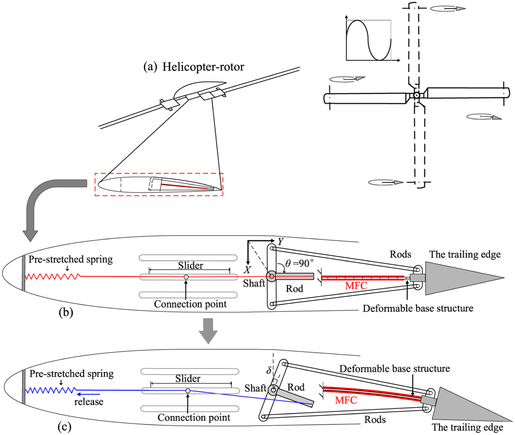
(a) Potential application scenario Zhang et al., 2022, (b) conceptual composition of the system, and (c) motion process.
Figure 1(a) shows the potential morphing process of the rotary wing over one cycle, with a fixed frequency determined by the rotor speed (Zhang et al., 2022). The concept here is that a stiffness tuning mechanism can be designed to tune the natural frequency of the actuator to generate resonance in different flight conditions. The conceptual composition of the system is shown in Figure 1(b), while detailed designs are not presented in the current study. The system is arranged within the blade, consisting of the stiffness tuning mechanism and MFCs bonded on the upper and lower surfaces of the deformable base structure, which will deflect the trailing edge when it bends. The stiffness tuning mechanism consists of one shaft and two rods connected to the trailing edge, one rod on the shaft, a pre-stretched spring, and a slider that can adjust the position of the spring connexion point. The rod on the shaft is oriented towards the trailing edge to increase the effective moment arm. The connexion point can be adjusted in position and fixed through a sliding groove. The position of the connexion point will affect the torque output of the mechanism thereby changing the stiffness tunning capability.
The stiffness tuning mechanism and trailing edge are connected by the two rods, which allows for stable force transmission during the actuation. The current study is focussed on the mechanism composition and actuation.
The rod with offset angle θ is rigidly mounted on the rotating shaft of the stiffness tuning mechanism, and the end of the rod is connected to the pre-stretched spring. The purpose of the connexion mechanism is to ensure effective transmission of the trailing edge rotational motion to the stiffness tuning mechanism. The rearward orientation of the rod maintains the spring in tension throughout the vibration cycle, thereby avoiding compressive instability and improving the robustness of the stiffness modulation process. The working process of stiffness tuning mechanism summarised in Figure 2.
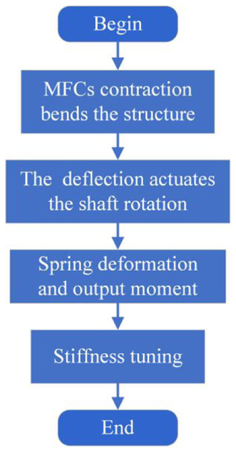
Working process of the stiffness tuning mechanism.
The MFC actuators are placed in the antagonistic configuration, which are bonded symmetrically on the upper and lower surfaces of the base structure. Bending is generated through differential actuation of the two MFC layers. By applying out-of-phase driving voltages, one MFC undergoes axial extension while the other contracts, producing a bending moment about the neutral axis. This differential strain induces the trailing edge deflection and drives the subsequent shaft rotation of the stiffness tuning mechanism. This actuation scheme corresponds to an antagonistic configuration. At the same time, the deflection will lead to the rotation of the shaft through the connected vertical rods. The grey rod, which is rigidly mounted on the shaft, rotates simultaneously. Since one end of the rod is connected to the pre-stretched spring. Thus, the rotation will actuate the pre-stretched spring to release or further stretch, which will generate a moment onto the trailing edge. The moment will reduce or increase the moment required for structural deformation, thereby tuning the structural stiffness effectively. The direction and magnitude of the moment generated by the pre-stretched spring will affect the stiffness tuning mechanism, and cause different stiffness changes. However, it should be noted that this study is limited to model the spring with a linear stiffness only.
The moment magnitude depends on the pre-stretched spring and the moment arm, which can be adjusted by the slide to change the position of the connexion point. The moment direction is determined by the offset angle θ of the rod. Once assembled, the offset angle θ remains constant during vibration and only serves to define the mechanical configuration corresponding to a specific stiffness state; when the θ = 90°, the moment direction is consistent with the rotation direction, the mechanism is beneficial to deflect of the trailing edge, and will decrease the requirement of the actuation moment. Conversely, when the θ = 270°, the moment is not helpful to the deflect the trailing edge, which will increase the requirement of the actuation moment.
Kinematic analysis
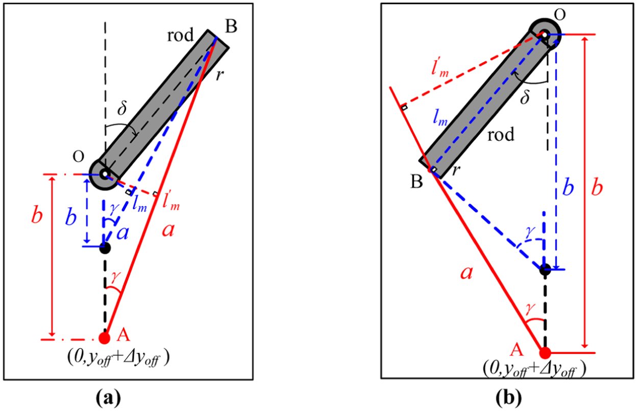
During the process of the rod rotation caused by the deflection produced by the MFCs, the offset angle θ will affect the direction of the moment generated by the spring. Two typical offset angles θ = 90 and 270° are shown in Figure 3.
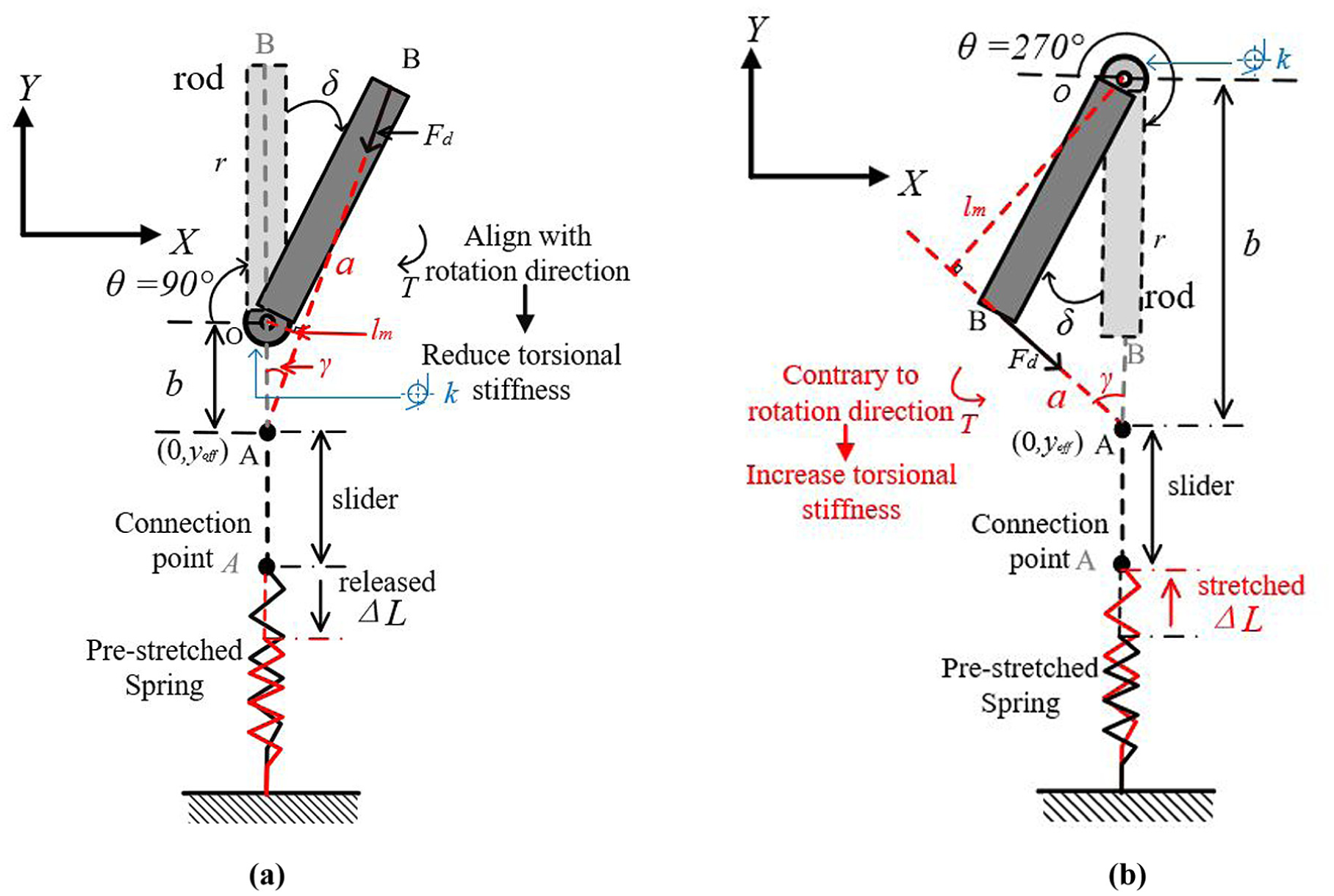
Mechanism motion analysis: (a) θ = 90° reduced stiffness state and (b) θ = 270° increased stiffness state.
The kinematics of the mechanism can be derived as followed. The point O is the origin, and a coordinate system is established. Thus, the coordinates of point B can be expressed according to the geometric relationship as
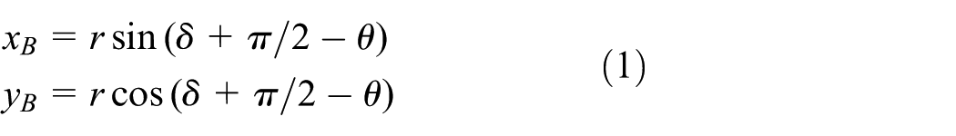
where δ is the rotation angle of the shaft and r is the length of the rod. Point A is the connexion point of the spring, and its coordinates are

where y off is the movable slider position. The length a between Point A and B is
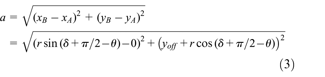
From this, γ can be found by the cosine theorem, and hence the moment arm l m is
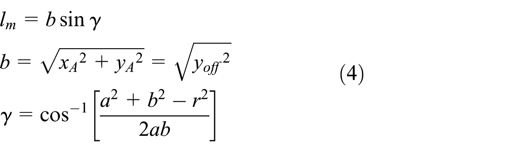
The moment provided by the stiffness tuning mechanism is generated by the spring with an initial pre-stretched length L0, and the spring stiffness is k d . During the rotation, the moment T is
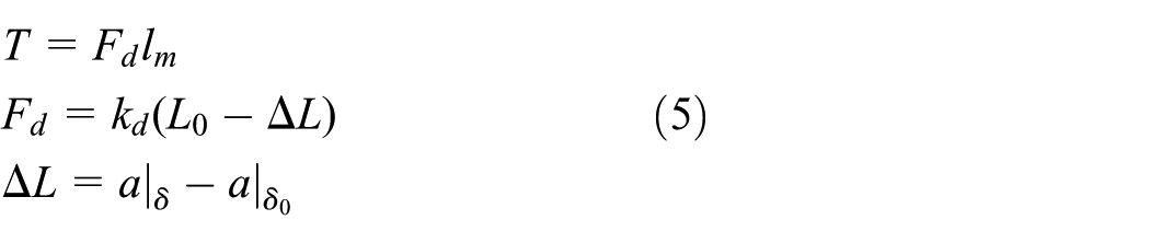
The pre-stretched spring in the initial state produces no moment. However, in the subsequent process of actuating the trailing edge deflection and the rod rotation by MFCs, the magnitude and direction of the moment generated by the pre-stretched spring are different.
When θ = 90°, the spring is released and provides a moment, which is transmitted to the shaft. The moment is in the same direction of the rod rotation, and thus it reduces the moment requirement of the trailing edge deflection. In contrast, at θ = 270°, the spring is extended and requires an extra moment, which will increase the moment required for the trailing edge deflection.
Due to the symmetry of the mechanism, only the moment output caused by the downward deflection of the trailing edge is analysed, which corresponds to the clockwise rotation of the rod. The moment is defined as positive if it is clockwise and negative if counterclockwise. Based on the limitations of the experimental model and available tools, while also taking into account the results of the kinematic analysis mentioned earlier the relationship between the moment output and rotation is analysed using the parameters kd = 4200 N/m, L0 = 30 mm, r = 50, and yoff = 30 mm the results are illustrated in Figure 4.
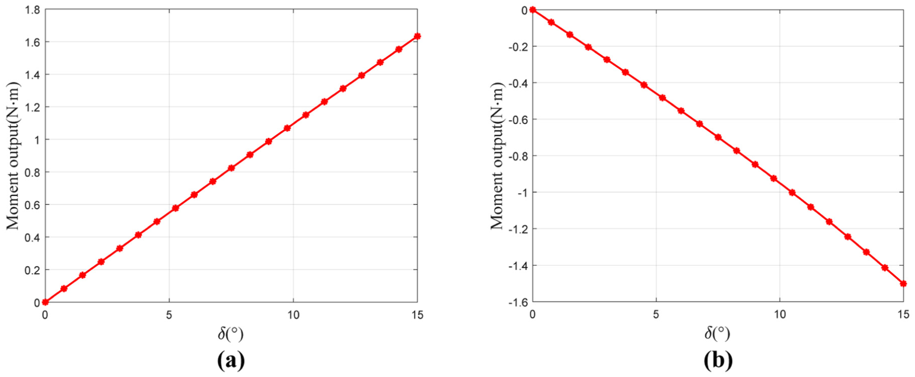
Moment output during rotation: (a) θ = 90°, reduced stiffness state and (b) θ = 270°, increased stiffness state.
When θ = 90°, during the rod rotation, the output moment is positive, which means the spring promotes the rod rotation, thereby helping the trailing edge deflection. The stiffness tuning mechanism effectively reduces the required actuation moment for a given deflection, resulting in a reduction of the equivalent rotational stiffness. This effect can be interpreted as a negative stiffness contribution that modifies the overall system stiffness. Conversely, when θ = 270°, the mechanism provides the positive stiffness.
As shown in Figure 4, the moment output increases approximately linearly with small rotation angles δ. Hence, the device is modelled as a spring with a linear negative stiffness of Δk. Similarly, it can be inferred that at θ = 270°, the device can be modelled as a spring with a linear positive stiffness of Δk.
However, it should be noted that the greater the force generated by the spring, the greater the frictional loss during the motion, resulting in an increase in the damping of the system. This means that the stronger the stiffness tuning ability, the greater the damping of the system. To simplify the analysis, this article assumes that damping varies linearly with Δk.
The kinematic analysis of the stiffness tuning mechanism shows that the moment arm l m can be changed by modifying the position of connexion point A. The overall stiffness of the system can be adjusted accordingly. The principle and the geometry relationship are illustrated in Figure 5.
Stiffness tuning principle: (a) θ = 90°, reduced stiffness state and (b) θ = 270°, increased stiffness state.
After the position of the connexion point changes, the moment arm l m becomes l′ m

As can be seen from Figure 5, both b and γ change with the connexion point. The essence of changing the connexion point is to modify the moment arm l m and ΔL during the rotation. Based on the above analysis, using the parameters kd = 4200 N/m, L0 = 30 mm, r = 50 mm, δ = 15°, the connexion point position was analysed when the offset position yoff varies from 30 to 90 mm, as shown in Figure 6.
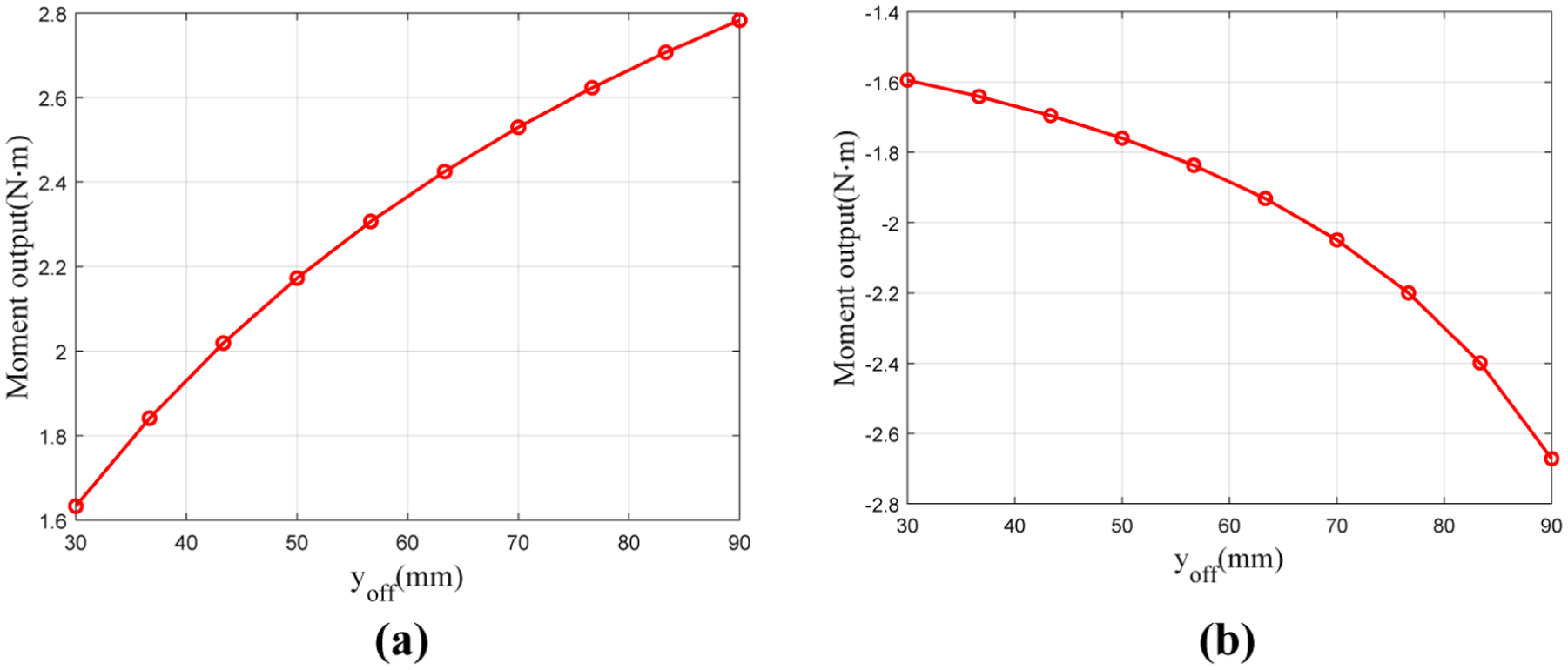
Moment output with connexion point position: (a) θ = 90°, reduced stiffness state and (b) θ = 270°, increased stiffness state.
It can be seen that the moment output increases when yoff increases. In the reduced stiffness state, by changing the position of the connexion point, the moment output is changed from 1.6 to 2.8 N·m. On the other hand, the moment output is changed from −1.6 to −2.7 N·m in the increased stiffness state. Similar relationships between the moment output and the connexion point position can be obtained for the cases when the angle δ varies and the change of the moment output means it is feasible to tune the structural stiffness by changing the position of the connexion point.
In summary, the moment output of the stiffness tuning mechanism can be changed by the offset angle θ and the position of the connexion point. With proper design and optimisation, the stiffness tuning capability may be enhanced without changing the basic geometry of the mechanism.
Analysis of the resonance characteristics
Two models with different fidelity levels are adopted to demonstrate the feasibility and generality of the proposed stiffness tuning concept. The theoretical model reveals the fundamental resonance behaviour, while the finite element model evaluates the concept with higher structural fidelity. Since the two models differ in parameterisation, no direct mapping is enforced. The results are thus normalised to their respective untuned baselines to compare tuning trends instead of absolute values.
Theoretical analysis
The kinematic model of the actuation system is established. The MFCs are simplified as periodic excitation, the stiffness tuning mechanism is simplified as the change of the system stiffness. On this basis, the system can be modelled as the forced oscillation in a single-degree-of-freedom system under periodic excitation, as shown in Figure 7.
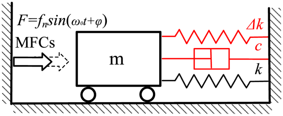
Equivalent single degree of freedom forced oscillation.
Previous work has considered the negative stiffness mechanism consisting of a cubic stiffness applied to a classical mass-spring-damper system. Based on the analysis of moment output in Section 2, this paper simplifies the stiffness tuning mechanism by modelling it as a change in stiffness Δk, which is a function of u(t) in reality. The friction and the loss of the kinetic energy introduced by the mechanism are equivalent to the change of system damping c. The current study only makes a preliminary investigation of the actuation concept, and the aerodynamic stiffness and damping are not taken into account. The equation of motion can be written as
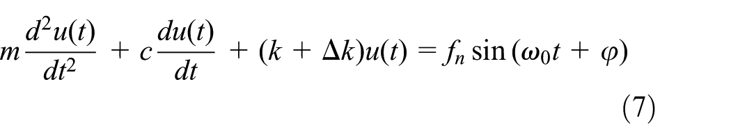
where f n is the force provided by the actuator, and m, k, and c are the mass, stiffness and damping respectively. The introduction of a stiffness tunning mechanism will cause the change of the stiffness Δk of the original system. Since the theoretical analysis is to find the basic trends and the results will be nondimensionalised, the simple parameters m = 1, k = 55, and c = 0.1 are used. The parameter values are chosen to illustrate the frequency tuning mechanism and are not intended to correspond to a specific hardware configuration. Since the theoretical analysis aims to capture general tuning trends, the qualitative conclusions remain valid for other parameter sets within reasonable physical ranges.
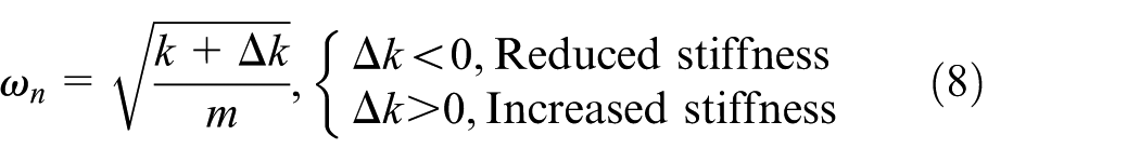
The natural frequency of the system in the reduced stiffness state and the increased stiffness state can be obtained respectively as:
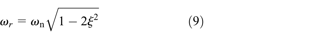
The resonance frequency ω r is
With
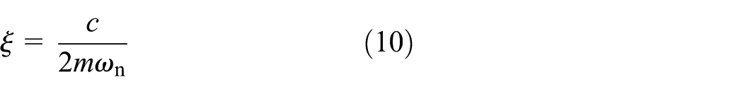
The resonance amplitude B d is
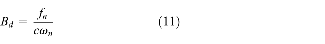
Based on the above analysis, the oscillation equation of motion can be solved to give the response as
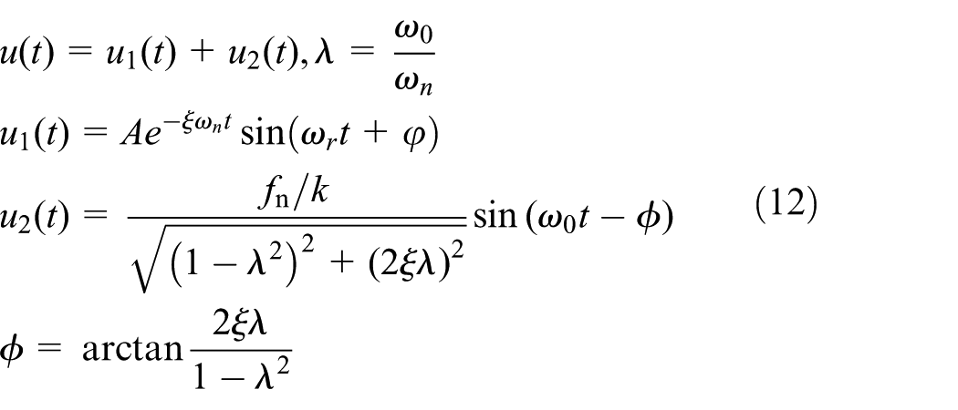
where x(t) is the solution of the oscillation equation of the system, and x1(t) and x2(t) are the general solution and the specific steady state solution, respectively. A is the amplitude, and ξ is the damping ratio, φ is determined by initial conditions, ϕ is determined by system parameters.
In the presence of damping, x1(t) is only meaningful for a short period of time in the early stages of oscillation, and as time increases, it will gradually decay to zero. Hence, the subsequent analysis is based only on the steady-state response x2(t). Based on equation (12), a frequency response analysis is performed. In the theoretical model, the baseline case corresponds to Δk = 0, representing the configuration without stiffness tuning. The results will be discussed together with those of the finite element analysis in Section 3.2.
Finite element analysis
In addition to the theoretical analysis, finite element simulation is also conducted to verify the theoretical analysis. As shown in Figure 8, the finite element model of the base structure is created in the commercial software Abaqus®. A composite plate is used as the base structure, which is made of the carbon fibre material. 12 plies are applied and each ply has a thickness of 0.1 mm with the ply angles arranged at 0° and 90° in sequence. The use of resin material modelling for the trailing edge is to resemble the shape of the wing while maintaining consistency with the experimental setup. The trailing edge root is fully clamped. A reference point at the actuation location is coupled to the surrounding nodes using an MPC tie constraint. An axial connector linking this point to a fixed point generates a force, which produces an additional moment at the clamped root and modifies the equivalent rotational stiffness, thereby representing the stiffness tuning effect.
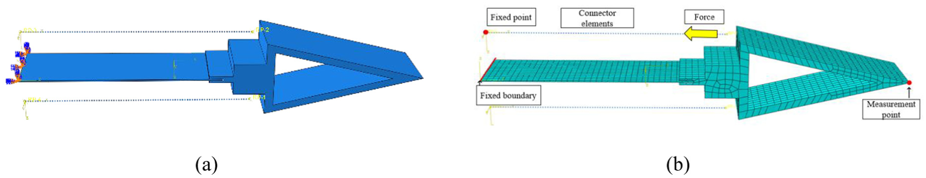
FEA model setup: (a) geometry of the finite element model and (b) meshes of the model.
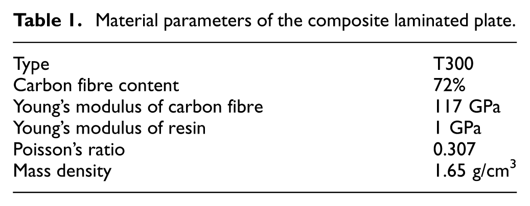
The MFC was not modelled directly in the finite element model and its actuation effect was regarded as an external excitation. The composite material parameters are shown in Table 1.
Material parameters of the composite laminated plate.
The stiffness tuning mechanism is considered as a torque input to the finite element model. By changing the magnitude and direction of the torque, the required torque for structural deformation can be reduced or increased, achieving stiffness tunning. The torque is determined by the parameters of the stiffness tuning mechanism, and obtained through kinematic analysis, which is simulated by connector elements. In the finite element model, the baseline case corresponds to zero tuning torque, meaning that no additional moment is applied.
Results and comparisons
This subsection compares the frequency tuning trends predicted by the theoretical and finite element analysis. The frequency response obtained from the theoretical formulation is presented in Figure 9(a), while the corresponding response analysis of the finite element simulation is shown in Figure 9(b).
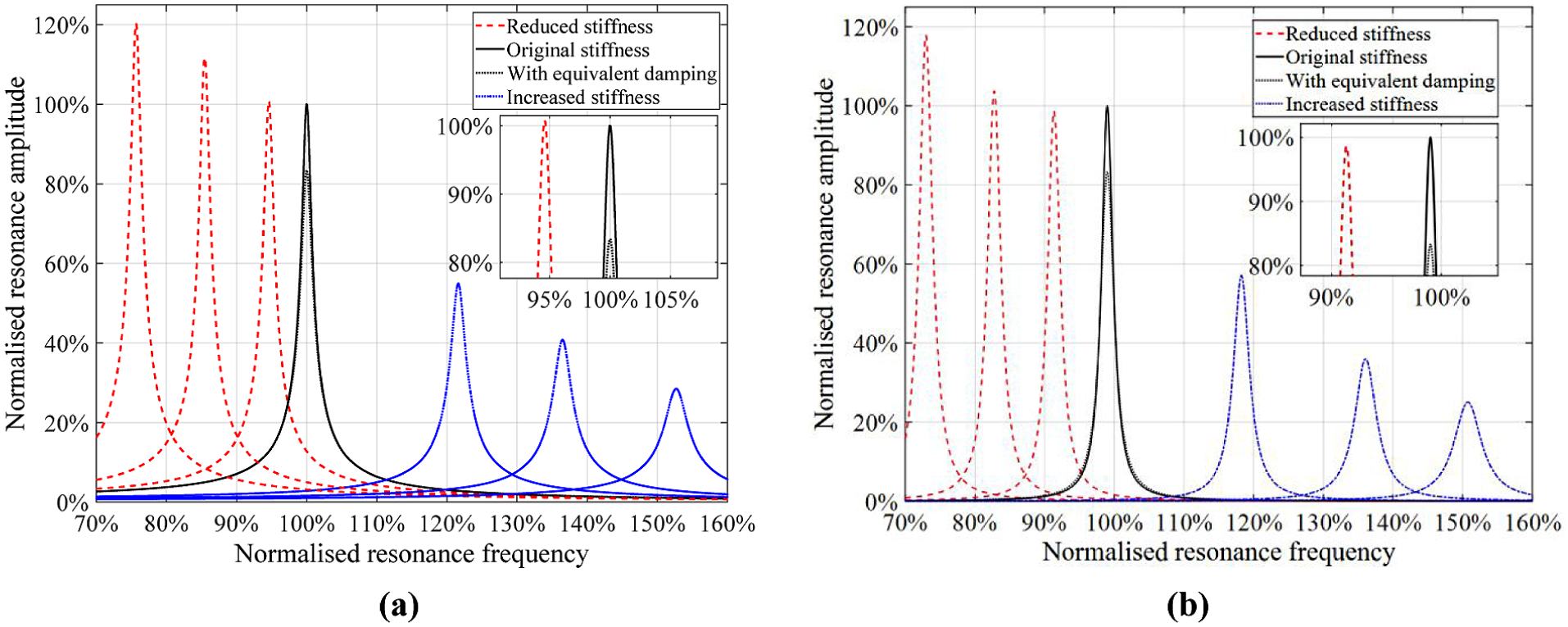
The amplitude frequency characteristic curve of the model at different resonance frequencies: (a) theoretical analysis and (b) finite element analysis.
The amplitude and frequency are normalised by the amplitude and resonance frequency of the structure without the stiffness tuning mechanism. The stiffness variations shown in Figure 9 are selected to span a representative range of stiffness variations around the baseline configuration, to illustrate the effect of stiffness tuning on the resonance response. The selected values are representative points within the admissible design interval and are not intended to establish a one-to-one correspondence between the analytical stiffness increment Δk and the finite element tuning torque.
The change trend is similar after the introduction of the stiffness tuning mechanism. After introducing equivalent damping, the amplitudes both are reduced to about 83% of the original amplitude.
In the reduced stiffness state, as the tuning ability increases, the resonance frequency decreases and the amplitude increases. However, the initial amplitude increase is relatively low compared to the subsequent decrease in stiffness, because the mechanism introduces new damping, which offsets the benefit. The increase in damping and the enhancement of stiffness tuning capability both lead to a decrease in amplitude and increase in frequency, in the increased stiffness state. The theoretical analysis results agree well with the results of the finite element analysis, which verifies the feasibility of the theoretical analysis. While Figure 9 presents the stiffness dependent responses within each model separately, Figure 10 provides a direct comparison of the normalised tuning trends between the two models.
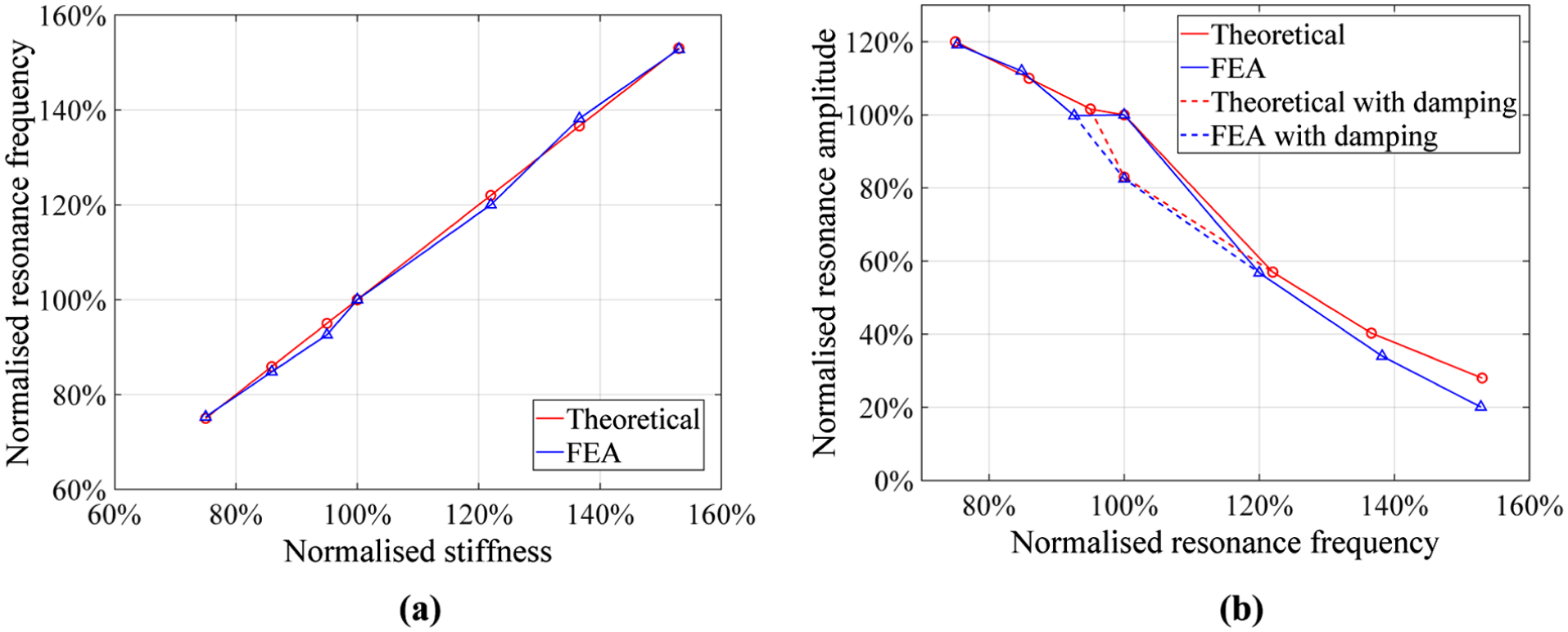
Changes in resonance frequency and amplitude caused by stiffness variations: (a) frequency comparison and (b) amplitude comparison.
To further verify the feasibility of the theoretical analysis, the changes of the natural frequency caused by changes in stiffness are compared. The theoretical analysis results are calculated using equation (8), while the finite element simulation results are obtained through modal analysis. Both results are normalised by the original stiffness and natural frequencies, as shown in Figure 10(a). The comparison trend indicates that the error between the two results is approximately 1%, which again verifies the accuracy of frequency analysis.
The relationship between the resonance amplitude and the natural frequency is also compared and analysed in Figure 10(b). The dashed lines in the figure correspond to the results with the equivalent damping, which are obtained from the Figure 9.
With the action of the stiffness tuning mechanism, as the resonance frequency increases, the resonance amplitude decreases. The trends of theoretical analysis and FEA are consistent and the amplitude difference is about 8%. Thus, according to Figures 9 and 10, the feasibility of the theoretical analysis and the effect of the proposed stiffness tunning mechanism have been demonstrated.
Optimisation of the stiffness tuning mechanism
To extend the range of tunable resonance frequencies, the stiffness tuning mechanism can be optimised based on the structural stiffness of the piezoelectric actuator and flap, for which accurate determination of the structural stiffness is required. During vibration, the plate undergoes upwards and downward deflection. Due to the clamped boundary condition at the root, the deformation can be approximated as a rotation about the fixed end. The restoring effect provided by the clamped support can therefore be represented by an equivalent torsional moment. Accordingly, the dynamic behaviour of the plate is modelled as a torsional spring system, in which the effective stiffness corresponds to the torsional stiffness about the fixed support. The structural stiffness of a manufactured composite plate was experimentally determined using a torque wrench to be 0.22 N·m/°.
Based on the previous analysis, a wider range of moment output provided by the mechanism leads to a wider range of tunable frequency. Considering the size of the model, the achievable range of variation for the offset point position yoff is 30–90 mm. Therefore, the optimisation objective is to maximise the moment output range, thereby enlarging the corresponding range of the tunable stiffness. Thus, the objective of the optimisation can be expressed as
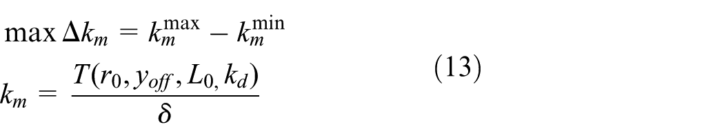
Here, k m is the coefficient representing the amount of stiffness that can be generated by the stiffness tuning mechanism, defined as the moment of the stiffness tuning mechanism divided by the corresponding rotation angle.
The design variables that can be optimised include: Rod length r0, Spring pre-stretched length L0, Spring stiffness kd. The stiffness tuning mechanism is optimised separately in two states θ = 90 and 270°, and the mechanism needs to be integrated into the wing and without any interference during movement. So, the possible intervals of the variables are given in Table 2.
Stiffness tuning system design variable.
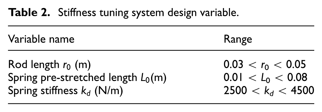
Considering the integration inside the wing, the rod length of the mechanism must be less than the wing thickness t w . By designing the mechanism, the connexion of the rods should not affect the transmission of the mechanism. Thus, the geometric constraint is

The genetic algorithm is applied for optimisation based on the motion analysis. The genetic algorithm parameters are set to a population size of 50, a termination evolution generation of 200, a crossover probability of 0.6, and a mutation probability of 0.001, which were based on the setup in the previous work (Zhang et al., 2019a). Table 3 presents the optimisation results of the two states. The optimisation was performed using a genetic algorithm. The algorithm was terminated after a predefined number of generations once the improvement in the best objective value became negligible. To assess the robustness of the optimisation and mitigate the risk of premature convergence, the GA was executed multiple times with different initial populations. The obtained optimal solutions were consistent across runs, indicating satisfactory convergence behaviour.
Optimised design parameters and results.
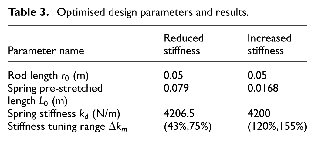
The optimisation results show that the maximum rod length is selected in both stiffness states, as a longer rod provides a larger moment arm and enhances the effectiveness of stiffness tuning. The spring stiffness consistently reaches the upper bound of the prescribed design range, indicating that the objective function increases monotonically with spring stiffness within the considered interval. The optimised pre-stretched length differs between the reduced and increased stiffness states. A larger pre-stretch is required in the reduced stiffness state to effectively counteract the baseline rotational stiffness, whereas a smaller pre-stretch is sufficient in the increased stiffness state due to the additive contribution to the equivalent torsional stiffness. The frequency tuning range of the two states in the theoretical analysis is shown in Figure 11.
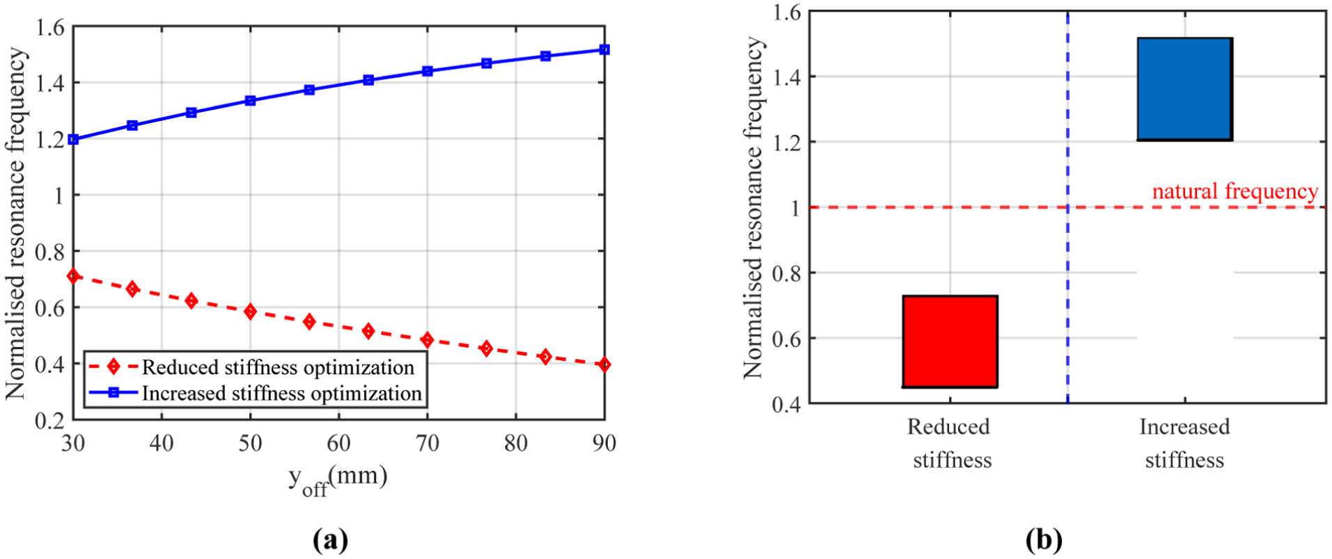
(a) Resonance frequency change with connexion point position and (b) resonance frequency modulation range.
The connexion point position of the stiffness tuning mechanism has been analysed in Section 2, and the stiffness tuning capability increased with the increase of yoff. The optimisation results showed that the stiffness tuning mechanism in the reduced stiffness state reduced the overall stiffness from 75% to 43%. While, in the increased stiffness state it increases the overall stiffness from the initial 120%–155%.
A range-based sensitivity analysis was conducted to evaluate the relative influence of the design variables on the stiffness tuning capability. For each design variable, its value was varied from the lower bound to the upper bound of the predefined admissible interval, while the remaining variables were fixed at their respective optimal values.
Within this interval, the objective function was evaluated across the full range of the variable. The sensitivity value shown in Figure 12 represents the difference between the maximum and minimum objective values obtained over this range, expressed relative to the objective value at the optimal solution. Therefore, the reported percentage indicates how much the objective function changes when one parameter spans its entire allowable design interval.
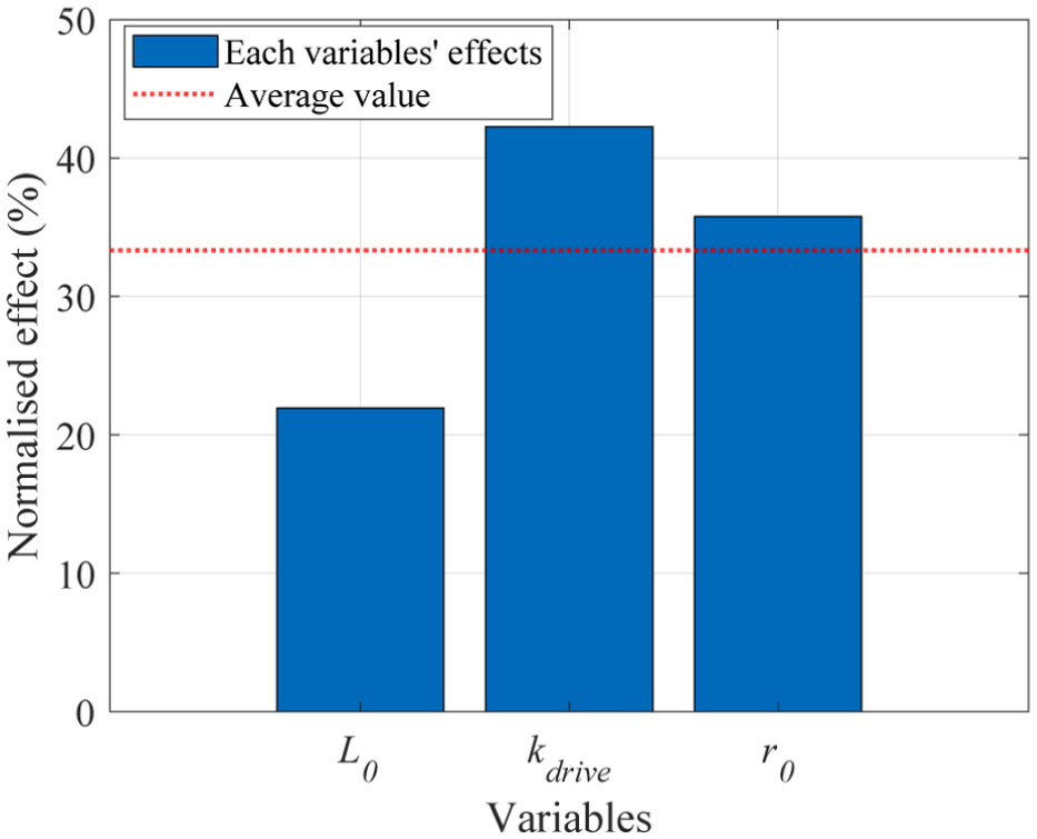
Parameter sensitivity analysis.
The results are presented in Figure 12. It can be observed that spring stiffness and the rod length exhibit a greater influence on the objective function compared to the pre-stretch length. The dashed line indicates the average sensitivity level among all variables.
Experimental verification
Demonstrator
In the current study, the experimental model is mainly to demonstrate the feasibility of the proposed concept and explore the basic trend of the mechanism.
Thus, the choice of the model dimension is based on the available tools such as the size of the piezoelectric actuators. In the future, we plan to perform further integration and optimisation for the more practical applications. A demonstrator is manufactured to verify the stiffness tuning mechanism. The aerofoil of the demonstrator is NACA0017 with a span of 100 mm, a chord of 663 mm and a maximum aerofoil thickness of 113 mm. The demonstrator includes a stiffness tuning mechanism and a composite laminate working as the deformable base structure with MFCs attached as shown in Figure 13(a).
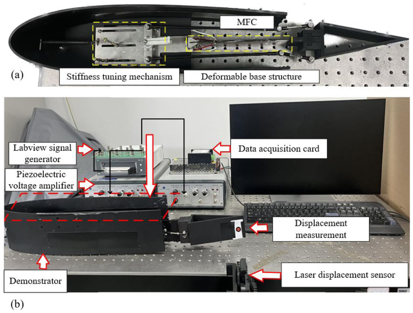
Experimental setup: (a) integrated demonstrator and (b) overall design of the experimental platform.
The stiffness tuning mechanism with the optimised parameters is installed, the mechanism consists of rods and a pre-stretched spring, both connected to a base fixed on the test bench. The rod length of the mechanism is 50 mm, and the spring stiffness is 4200 N/m. The complete experimental setup is illustrated in Figure 13(b).
The MFCs are bonded to the deformable base structure. A Labview® based on control is utilised to produce two sinusoidal signals with a phase difference of 180°. The signals are then given to two power amplifiers, which are connected to the MFCs on the upper and lower surfaces accordingly.
To prevent damage during the actuation of the MFCs, the voltage output signal amplitude from the signal generator is set to a sine wave ranging from −2 to 4 V, and the amplification factor of the piezoelectric voltage amplifier is 200. Since the trailing edge surface is black, the laser displacement sensor cannot provide sufficient measurement accuracy due to low reflectivity. Therefore, a white reflective patch was applied to the measurement location to improve displacement measurement accuracy. The tip of the trailing edge amplitude is measured by a laser displacement sensor, with a measurement range of 400 ± 100 mm and the accuracy of ±0.05% of the range.
Then, the oscillation amplitude of the structure is measured by exciting the MFCs with a varying frequency. As shown in Figure 14(a), the frequency response is obtained by sweeping the frequency. And the largest trailing edge oscillation amplitude can be achieved when the excitation frequency of the MFCs comes close to the resonance frequency 7.5 Hz. The oscillation displacement of the trailing edge is also compared in Figure 14(b) at 1 and 7.5 Hz, which shows an amplitude of 3.5 and 16.8 mm, and is equal to 0.53% and 2.53% of the chord respectively, the amplitude in resonance state is much larger than the displacement under static actuation.
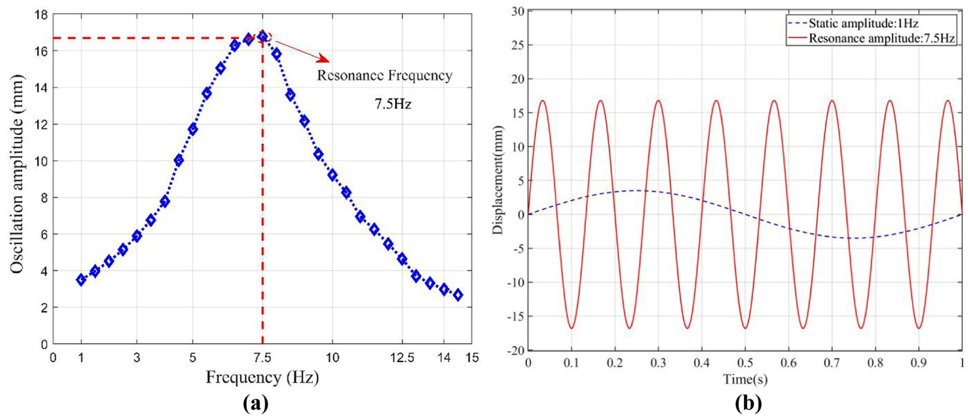
(a) Frequency response of the trailing edge oscillation and (b) oscillation displacement at 1 and 7.5 Hz.
To verify the ability of the mechanism to tune the resonance frequency, the following experimental steps are performed, as shown in Figure 15. Firstly, the optimised stiffness tuning mechanism is installed and a sweep frequency test is performed to induce resonance, which includes watching the amplitude change and adjusting the frequency. The maximum amplitude obtained through the displacement sensor is the resonance amplitude, and the actuation frequency at that time is the resonance frequency. Afterwards, multiple experiments are conducted by changing the position of the connexion point, and the above steps are repeated to obtain the resonance frequency and amplitude at different positions of the connexion point.
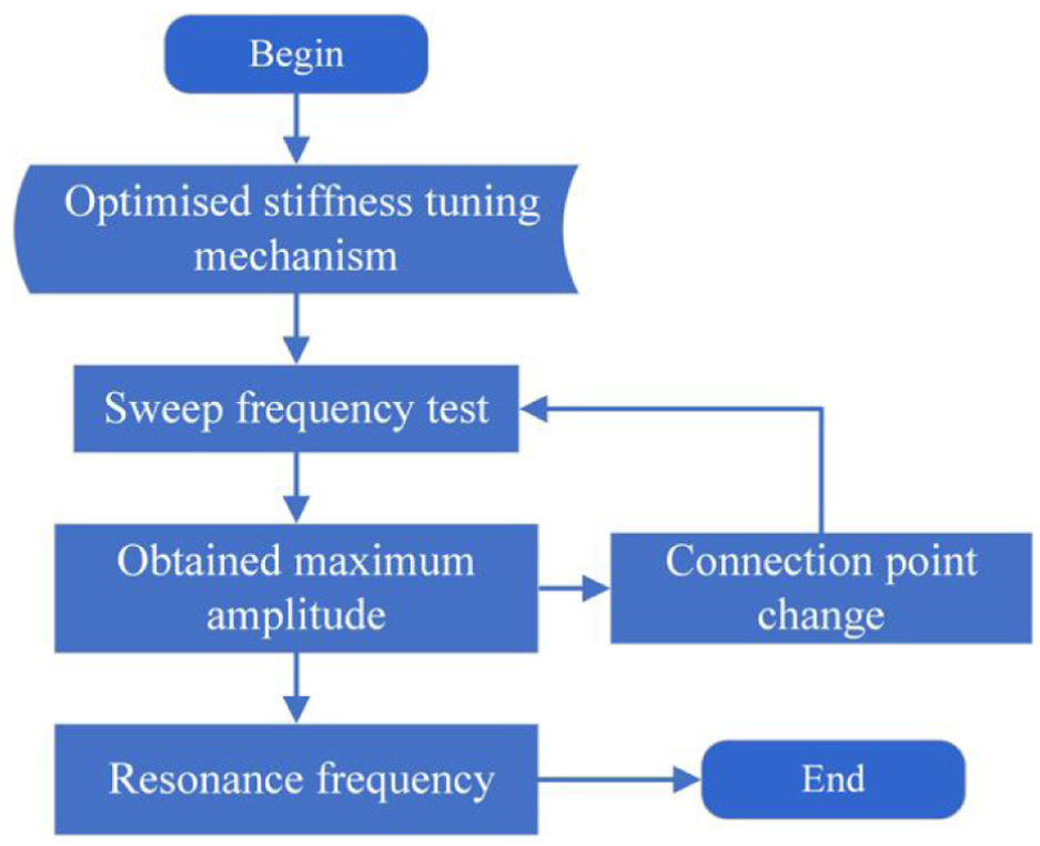
Experiment flowchart.
Experiment results
Following the above experimental steps, the resonance frequency and amplitude obtained from the reduced stiffness state are shown in Figure 16.
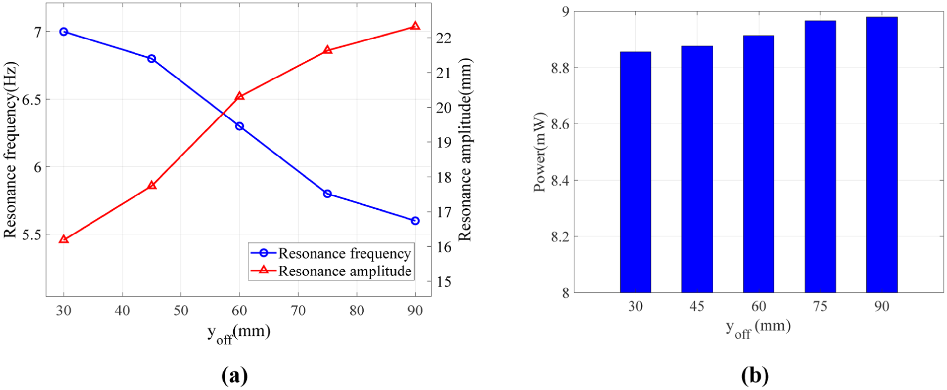
Frequency modulation results in reduced stiffness state: (a) amplitude and frequency and (b) power.
The stiffness tuning mechanism is set to the reduced stiffness state with an offset angle of θ = 90°. The connexion point position is varied from 30 to 90 mm from the origin, and a frequency sweep analysis is performed for each configuration to obtain the corresponding resonance frequency and amplitude.
As the connexion point moves farther from the hinge, the effective moment arm increases, resulting in a decrease of the resonance frequency from 7 to 5.6 Hz and a simultaneous increase in the resonance amplitude from 16.2 to 22.3 mm. With the stiffness tuning mechanism, the system resonance frequency decreased to 75% of the natural frequency, while the amplitude increased to 136% of the original resonance amplitude.
The power P used for oscillation can be calculated with the experimental results using the following equation (Zhang et al., 2022).
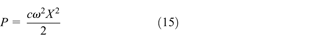
Where c is the damping coefficient, ω is the frequency, and X is the amplitude. It can be seen from Figure 16(b) that as the position of the connexion point increases from 30 to 90 mm, the power consumption remains stable with only 5% increase.
In the increased stiffness state, the stiffness tuning mechanism is set to an offset angle of θ = 270°. As shown in Figure 17, when the connexion point position is varied from 30 to 90 mm from the origin, the resonance frequency increases from 9 to 11.3 Hz, while the tip displacement amplitude decreases from 9.9 to 6.3 mm.
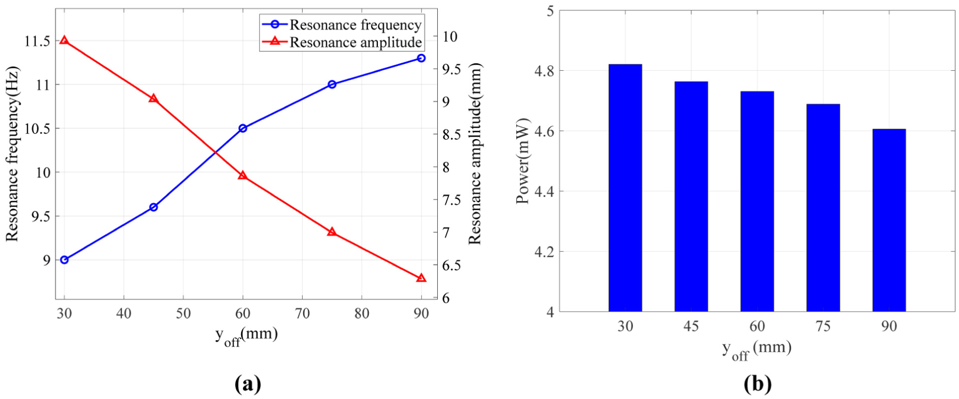
Frequency modulation results under increased stiffness state: (a) amplitude and frequency and (b) power.
In Figure 17(b), the power used for oscillation is less than the reduced stiffness state, which could be due to the increased power cost by the stretching spring. However, as the position of the connexion point increases, the power consumption remains stable generally with a 9% reduction, which still shows the stable power requirement of the resonance actuation.
In all cases, the excitation amplitude applied to the actuator is kept constant, and only the excitation frequency is varied. Therefore, the reported amplitudes refer to the output displacement response of the structure. The resonance frequency reaches approximately 153% of the baseline natural frequency. Although the resonance amplitude decreases as the frequency shifts upwards, it remains at least 171% of the baseline displacement amplitude obtained in the untuned configuration under the same excitation level.
Overall, the resonance frequency can be varied from 75% to 153% of the original frequency, which shows the effect of the stiffness tuning mechanism on expanding the working frequencies of the resonance actuation method.
Conclusion
This article presents the conceptual development of a stiffness tuning mechanism for a piezoelectric resonance actuation system. The stiffness tuning mechanism was designed, analysed and verified through theoretical, numerical and experimental study. Furthermore, the following conclusions can be made:
(1) A stiffness tuning mechanism was proposed based on the rod with a variable offset angle θ, which has two different states corresponding increased and reduced stiffness respectively.
(2) The kinematics of the mechanism was derived and theoretical and finite element analysis show that by changing the stiffness of the mechanism, the resonance frequency can be varied.
(3) The mechanism was optimised to increase the range of the stiffness change, which can increase the range of the resonance actuation.
(4) A demonstrator was built and experimental work was performed, which showed that the resonance frequency was varied when the tuning mechanism was activated. In the current study, the tuning mechanism made the structural resonance vary within the range 75%–153% of the natural frequency.
In this study, the stiffness tuning mechanism was applied to the linear stiffness system, and the theoretical analysis and integrated experimental verification were carried out, the results of which were consistent. The effect of the aerodynamics was not considered, which could lead to the reduction of the overall efficiency of the mechanism. A more detailed modelling and analysis will be performed in the future study to further evaluate the proposed mechanism. The current research is focussed on the conceptual verification. In the future study, nonlinearity will be considered, and the detailed design of the mechanism and the wing will be performed together with the integration process of the mechanism.
Footnotes
Appendix
Funding
The authors disclosed receipt of the following financial support for the research, authorship, and/or publication of this article: The first three authors would like to acknowledge the funding from National Natural Science Foundation of China (Grant No. 52305262) and the Starting Grant of Nanjing University of Aeronautics (Grant No. YQR22056). The fourth author would like to acknowledge the funding from National Natural Science Foundation of China (Grant No. 92271104) and Beijing Natural Science Foundation (Grant No. 1232014). This project also received funding from the European Union’s Horizon 2020 research and innovation program under grant agreement No. 723491.
Declaration of conflicting interests
The authors declared no potential conflicts of interest with respect to the research, authorship, and/or publication of this article.
Data availability statement
All data generated or analysed during this study are included in this published article.