
Abstract
Steer-by-Wire (SbW) systems eliminate the mechanical linkage between the handwheel and roadwheels, necessitating artificial tactile feedback to restore steering feel. This paper focuses on the design, optimization, and experimental validation of a compact magneto-rheological torque feedback device (MRTFD) intended for SbW applications. To accommodate the elongated axial geometry and severely limited radial envelope of SbW steering columns, an axially oriented comb-shaped MRF channel configuration is developed. This architecture enhances magnetic field utilization and load-carrying capability while maintaining a low off-state torque, enabling a wide controllable dynamic range within stringent geometric constraints. A constrained multi-objective optimization framework is employed to balance dynamic torque range and energy consumption under a prescribed maximum activated feedback torque constraint. The optimized design is subsequently fabricated and experimentally characterized, showing close agreement between measured and simulated torque responses. Furthermore, the prototype is integrated into an SbW steering test rig and evaluated under a feedback control scheme that combines a PID controller with inverse-model feedforward compensation. Experimental results demonstrate accurate torque tracking over various steering rates, thereby highlighting the feasibility and effectiveness of the proposed MRTFD for future SbW steering feedback applications.
Introduction
Steering systems are the mechanical and electronic assemblies that translate a driver’s inputs at the steering interface into controlled changes in wheel orientation. Growing demands for packaging flexibility, weight reduction, fuel efficiency, and seamless integration with advanced driver-assistance and autonomous functions have driven a historical evolution from purely mechanical or hydraulic linkages to power-assisted systems and, more recently, to fully electronic Steer-by-Wire (SbW) architectures. In SbW, steering commands are sensed, processed, and executed by electronic sensors, controllers, and actuators, effectively decoupling the steering interface from the road wheels. This architecture offers numerous benefits: faster, more precise control; simplified mechanical packaging; and the ability to implement customizable steering characteristics and tight cooperation with vehicle stability and autonomy systems. However, at the same time, removing the mechanical path deprives drivers of natural tactile cues, such as self-aligning torque and road texture, that are critical for situational awareness and safe control. Restoring these haptic signals in a compact, reliable, low-latency way is therefore a central challenge for SbW adoption and motivates research into efficient tactile-feedback solutions that meet modern packaging and safety constraints.
Recent studies on SbW technology have focused on replacing the driver’s lost cues with artificial haptic feedback generated by active torque control systems. Balachandran (2015) advanced artificial steering feel modeling by establishing stability and performance criteria for active steering and introducing predictive cues for shared control. Fahami et al. (2015) further developed an estimation-based torque-feedback strategy using gain-scheduled LQR control to reproduce realistic EPS-like steering feel in a hardware-in-the-loop platform. Addressing limitations of open-loop methods, Chugh et al. (2018) showed that closed-loop impedance control provides higher bandwidth and transparency than admittance schemes, and later proposed a unified inertia–spring–damper–friction reference model for both EPS and SbW feedback design (Chugh et al., 2020). In parallel, Finne and Ström (2022) emphasized perceptual realism by modeling road-induced torque components and surface roughness to strengthen driver trust and connection in SbW systems. Despite these advances, existing active torque-feedback systems face several limitations in practical deployment. They require bulky, power-intensive actuators and cooling systems to generate continuous high-bandwidth torques, which hinders compact integration and energy efficiency. Furthermore, their added inertia and transmission dynamics can distort high-frequency road feel and complicate coupled stability with vehicle controllers, while their reliance on complex estimation algorithms makes consistent perceptual fidelity difficult to achieve. These constraints have motivated the exploration of semi-active tactile feedback devices (TFDs), which modulate mechanical resistance rather than generating torque directly, offering low power consumption, inherent fail-safe behavior, and compact implementation.
Among various smart solutions, magnetorheological fluids (MRFs) provide an attractive enabling technology for semi-active TFDs. MRFs are suspensions of micron-scale, magnetizable particles in a carrier fluid whose rheological properties (apparent viscosity and yield stress) change reversibly and rapidly when exposed to a magnetic field. Under no field the fluid flows easily; when a field is applied, particle chains form and the fluid develops a controllable yield stress and increased shear resistance. Key practical features of MRF relevant to TFD design are: fast response, continuous and adjustable range of feedback torque proportional to field strength, high torque density for compact packages, and simple low-bandwidth control. Consequently, the MRF-based semi-active TFD (MRTFD) emerges as a promising solution that combines shaped hand-wheel dynamics with compactness, low power consumption, and fail-safe behavior to deliver responsive, robust haptic feedback. Building upon this potential, researchers have explored a variety of MRTFD structures to produce tunable haptic resistance for interactive systems. Diep et al. (2021) experimentally evaluated a 3D haptic joystick that integrates bidirectional MR actuators and a linear MR brake, demonstrating effective tangent and normal force generation while highlighting control issues that warrant further refinement. For vascular interventional teleoperation, Liu et al. (2022) developed and validated an MRF-based force feedback master robot whose low-inertia, reluctance-aware MRF damper design yields accurate and fast torque regeneration. Complementing these actuator advances, Lhommeau et al. (2023) showed that a nested 3D printed, compact, multi-disk MR clutch produced higher torque density with reduced inertia and viscous losses, pointing toward lighter and higher-performance human–robot actuators. In parallel, Song et al. (2023) proposed a master–slave interventional system featuring an MRF-based haptic master that preserves conventional surgeon posture while providing high-fidelity passive force feedback. Kikuchi et al. (2024) reported a redesigned twin-driven MRF actuator that effectively reduces torque ripple and improves dynamic responsiveness, advancing its applicability for haptic feedback in tele operative surgical systems. Later, Heo et al. (2024) demonstrated a miniaturized haptic dial employing a T-shaped shaft and dual shear/flow MRF actuation to obtain a closed magnetic path and wide, tunable resistive torque. Recently, Plante et al. (2025) provided analytical and experimental evidence that highly-geared MRF actuators, via fluidic decoupling and tunable damping, can overcome fundamental inertia–gearing and stiffness–damping trade-offs, thereby bridging haptic and cobot performance spaces.
In the context of SbW systems, the literature on MRTFDs remains notably sparse. Early works by Ahmadkhanlou et al. (2006) and Peretti and Zigliotto (2006) provided useful evidence that MRF devices can generate fast, low-power, and smoothly tunable resistive torque for steering-like interfaces, but both stayed at an elementary, pre-industrial stage in terms of structure and validation. Their designs were relatively bulky and lacked the optimization required for effective integration into steering columns, and no comprehensive evaluations on practical SbW prototype systems were reported. Despite two decades of broader MRTFD advancement in haptic domains, virtually no follow-up research has built upon these early demonstrations to produce improved, manufacturable devices for robust SbW architectures. Most recently, one study from our group has addressed MRTFDs for automotive applications (Hoang et al., 2024), but it was limited to modeling and simulation and did not include prototype development or experimental validation. The identified gap underscores the necessity of developing a compact, thoroughly optimized MRTFD specifically tailored to SbW systems, which forms the foundation for the research direction pursued in this paper. Configuration also plays a critical role in MRTFD performance, since geometry determines magnetic-circuit efficiency, operational MRF volume, and the device’s mechanical characteristics. Disk-type configurations can deliver high torque within a small axial package and are therefore popular where axial space is constrained but some radial clearance exists. Load capacity and dynamic range for such devices have been improved through various design strategies, including magnetic-circuit topology inspired by induction motors (Shi et al., 2025), multi-disk assembly (Kadam et al., 2024; Yang et al., 2024), T-shaped disk (Turabimana and Sohn, 2023), zigzag flux paths (Wellborn et al., 2022), and toothed rotor (Nguyen et al., 2022), but these approaches generally increase structural and manufacturing complexity. Another important drawback of large-diameter disk layouts is the added rotational inertia from mass distributed far from the axis, which complicates high-fidelity haptic control. Moreover, radial nonuniformity of flux density across MRF end-face channels can produce torque ripple that degrades smoothness of the rendered feedback. Drum-type designs form another category introduced in the literature (Hu et al., 2025; Singh and Sarkar, 2023; Wu et al., 2024); however, these configurations and their modified variants have been explored primarily for braking applications due to their high load capacity, large physical size, and substantial space requirements. The common upgrade approach of radially enlarging the structure, combined with the limited utilization of MRF activation on end-face channels, constrains the applicability of drum-type solutions in confined environments. MR rotary vane brakes/dampers have also been investigated as an alternative architecture for torque generation in haptic or suspension applications (Lutanto et al., 2022; Park et al., 2024; Saini et al., 2021). By exploiting magnetically controlled pressure drop across internal flow channels between adjacent chambers, these devices can generate relatively high torque within a compact radial envelope. However, sealing complexity, internal friction, and fluid inertia may limit their dynamic response and controllability for high-fidelity tactile feedback. Specifically, for SbW applications, only moderate feedback torque is required, sufficient to convey steering-direction cues without causing driver fatigue, and thus TFDs should prioritize smooth, natural-feeling haptics rather than high absolute torque. Because steering columns are typically long and slender cylinders, MRTFDs that employ continuous, small-diameter cylindrical shear surfaces along the steering shaft are often more suitable than conventional disk or drum configurations when radial space is constrained. Such shear interfaces tend to generate smoother and more uniform torque with reduced ripple, yielding a more natural steering feel. However, the small lever-arm radius inherently limits load capacity, which necessitates a more advanced design that increases the effective shear area per radial footprint to achieve the required torque levels within the strict geometric and packaging constraints of a steering column.
Overall, despite the considerable progress in MRTFDs, their application in SbW systems remains largely underexplored. Recent research efforts aimed at improving MRTFD configurations specifically for SbW steering feedback are scarce, leaving this topic as an open research problem. Furthermore, most existing MRTFD configurations are primarily designed to generate high torque, typically resulting in relatively large radial dimensions and increased rotational inertia, which may compromise compact integration and smooth torque feedback within the limited installation space surrounding the slender steering column. However, while a slender cylindrical MRTFD with a small diameter would be more suitable for steering column integration, the reduced lever arm associated with the small radius inherently limits the achievable torque output. Moreover, comprehensive experimental validation of MRTFD-based haptic feedback systems in practical SbW scenarios, together with appropriate control strategies for accurate torque tracking, remains limited in the existing literature. These considerations lead to the following research questions: (1) how to design a compact MRTFD compatible with installation constraints surrounding SbW steering columns while still providing adequate feedback torque; (2) whether the effective shear area can be enhanced to compensate for the limited torque capability caused by the small device radius; and (3) how such a device generates smooth and controllable torque feedback for SbW applications under an appropriate control scheme and experimental validation.
To address these questions, this study develops a compact MRTFD whose geometry and magnetic layout are specifically designed for integration within the limited radial space of SbW steering columns. While only limited recent research efforts on MRTFD applications in SbW systems have been reported, the main novelties of this work lie in the following aspects:
Compatible and compact architecture: The proposed device features an axial comb-shaped MRF channel that increases load capacity and improves dynamic range while maintaining a small outer diameter. In this configuration, each comb tooth is paired with an excitation coil, enabling enhanced controllable shear activation and improved torque modulation capability.
Advanced control strategy: A feedforward-feedback control scheme is proposed and implemented to achieve high torque tracking accuracy and improved dynamic response for SbW haptic feedback.
Thorough experimental validation: Comprehensive experiments in a practice SbW feedback environment are conducted to verify the effectiveness of the proposed MRTFD design and control strategy.
To obtain an effective design tailored for the steering application, a constrained multi-objective optimization procedure is performed, considering key criteria such as the number of comb teeth, expected feedback torque, dynamic range requirements, and available installation space. The optimized MRTFD is then prototyped and integrated into a functional SbW test rig for controlled tactile-feedback experiments and assessments.
Configuration and modeling
Figure 1 illustrates the configuration of the proposed comb-shaped channel MRTFD, which employs a slender cylindrical structure suitable for integration into compact-diameter steering modules of SbW systems. The device comprises a magnetic sleeve with an axial comb-shaped profile that is rigidly mounted on a non-magnetic shaft, forming the rotor element. Matching comb teeth are machined on the inner surface of a surrounding ferromagnetic cylinder, and the engagement of these two profiles establishes a comb-shaped set of narrow MRF channel segments. Each tooth on the sleeve is associated with a dedicated excitation coil tightly wound within the corresponding axial groove on the stationary cylinder. The assembly is sealed by lip seals, end covers, and supported by precision bearings to maintain MRF integrity and ensure stable rotational operation.
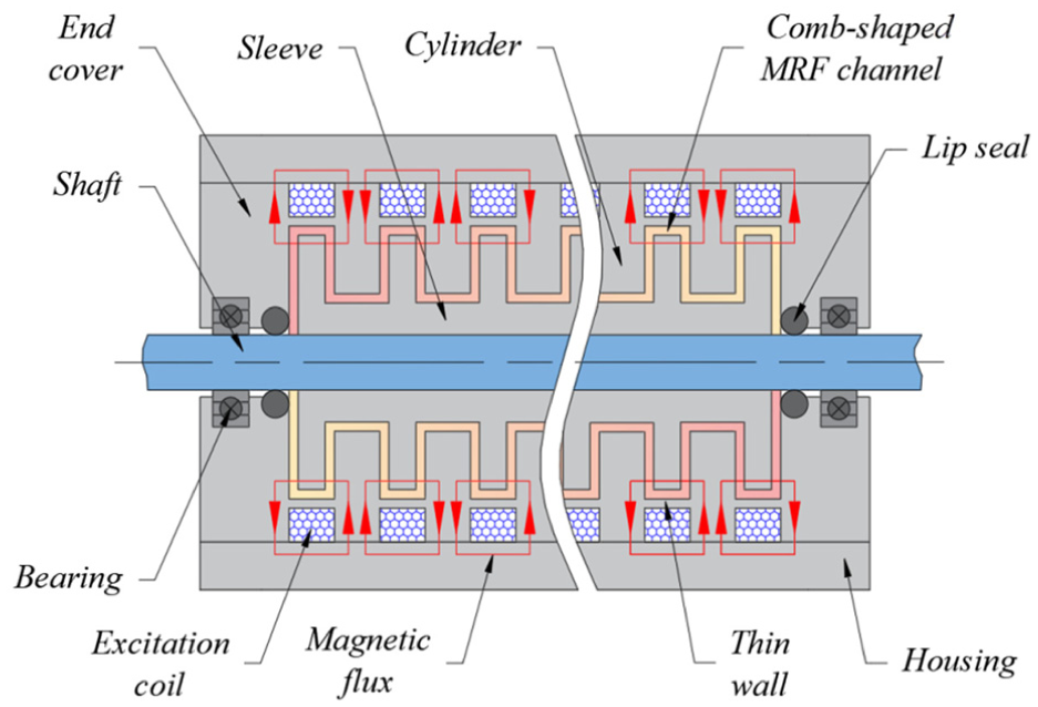
Configuration of the axial comb-shaped channel MRTFD.
The MRTFD operates in a shear-mode torque-modulation scheme, in which the MRF confined within the comb-shaped gaps experiences controllable yield stress under a magnetic field. In the off-state, the coils produce no magnetic field, allowing the rotor to spin freely with only mechanical friction and viscous resistance from the zero-field MRF. When a coil is energized, magnetic flux flows radially outward through the sleeve, rapidly saturates the thin ferromagnetic wall of the cylinder, and is redirected across the MRF gaps before returning along the adjacent tooth groove, completing a closed magnetic circuit. This flux distribution simultaneously activates both the axial and the radial channel segments, ensuring efficient utilization of the available MRF volume. The resulting field-induced yield stress significantly increases shear resistance, generating a controllable feedback torque on the rotor linked to the hand wheel. This modular configuration can be readily extended to a larger number of teeth and coils, provided that the current directions of adjacent coils are arranged oppositely to ensure consistent and properly guided magnetic flux paths.
In accordance with the operating principle described above, the modeling of the proposed MRTFD focuses on establishing an explicit relationship between the generated feedback torque and the device geometry as well as the applied magnetic field. The total feedback torque T fb acting on the rotor can be decomposed into three distinct components as follows:

The first component is the field-dependent yield torque T τ , which arises from the magnetically induced yield stress of the MRF within the comb-shaped shear channels, representing the dominant, actively controllable contribution. The second component is the viscous torque Tη, originating from the shear of the carrier fluid under relative motion between the rotor and stator, which persists even in the absence of the applied magnetic field. The third component is the frictional torque T f , mainly attributed to Coulomb mechanical losses between the rotating shaft and lip seals.
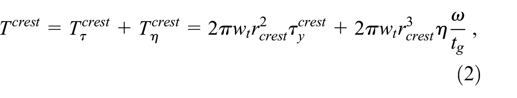
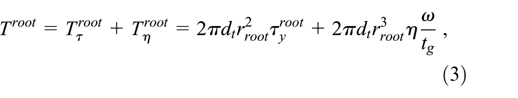
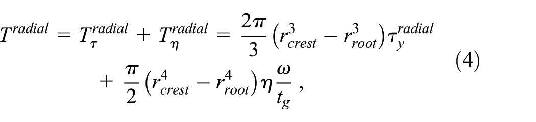
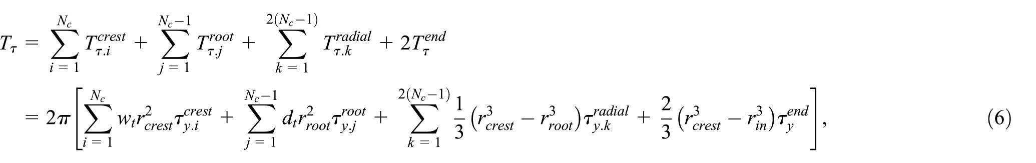
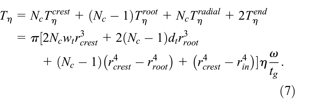
Figure 2 presents the fundamental geometric parameters of the axial comb-shaped channel MRTFD, which form the basis for modeling its controllable feedback characteristics. In this configuration, N c electromagnetic excitation coils are uniformly distributed along the axial length of the sleeve, establishing a one-to-one correspondence between the coils and the comb teeth. This arrangement defines multiple MRF channel segments, including N c crest segments, (N c – 1) toot segments, 2(N c – 1) radial segments, and two end-face segments. Owing to the small gap dimensions of the comb-shaped channels, the MRF flow within these regions is assumed to follow a linear shear velocity profile, and the magnetic flux density is considered spatially uniform within each activated channel segment. According to the Bingham plastic model, the MRF shear-induced torques T acting on the MRF channel segments can be determined as:
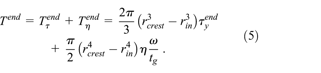
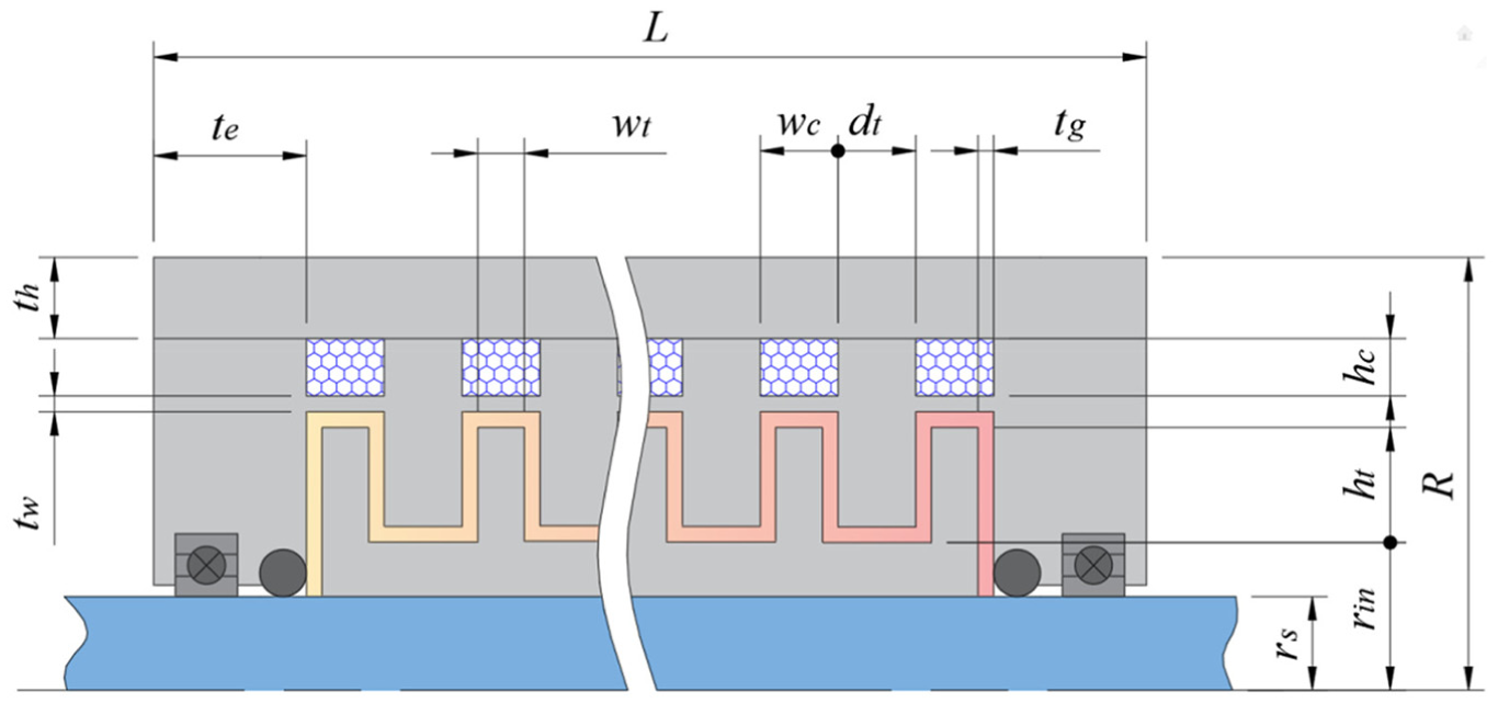
Fundamental geometric dimensions of the axial comb-shaped channel MRTFD.
In these equations, the superscripts crest, root, radial, and end refer to the crest, root, radial, and end-face MRF channel segments, respectively; ω is the angular velocity of the rotating shaft; τ y and η represent the yield stress and post-yield viscosity of the MRF; w t , d t , t g , r in , r crest , and r root are the geometric dimensions, respectively denoting the width of the comb tooth, the distance between two adjacent teeth, the thickness of the MRF gap, the inner radius of the sleeve, and the radii of the tooth crest and tooth root. Using these formulas, the yield torque Tτ and viscous torque Tη in equation (1) are calculated as:
The MRF employed in this work is a commercially available material supplied by Lord Corporation (USA), with the following intrinsic properties: grade MRF-132DG, carrier medium C = 1, volume fraction of suspended iron particles ΦFe = 0.32, and post-yield dynamic viscosity η = 0.092 Pa·s. The post-yield viscosity is considered to remain approximately constant over the operating range, whereas the yield stress exhibits a strong dependence on the applied magnetic field, which can be described by the empirical relationship given in the following equation:

where H represents the magnetic field intensity and the coefficients C and Φ Fe characterize the intrinsic properties of the MRF, including the carrier medium and the volume fraction of suspended iron particles.
The remaining contribution to the total torque, namely the friction torque T f , is evaluated using an experimentally derived expression reported in the literature by EPS Division (2021):

where r s and n s are the radius measured in meters and the spindle speed measured in rounds per minutes of the rotating shaft, respectively.
When no external magnetic field is applied (H = 0), the field-dependent yield stress τ y becomes zero, and consequently the corresponding yield torque Tτ disappears. Under this zero-field condition, the off-state torque T 0 is therefore composed solely of the viscous torque Tη and the mechanical friction torque T f , as expressed:

In addition to the achievable feedback torque, the energy consumption N constitutes another critical performance indicator of the MRTFD, as it directly affects operational efficiency and thermal behavior. The electrical energy required by the device is mainly determined by the excitation current I and the coil resistance R c as follows:

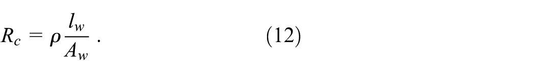
Here, ρ denotes the electrical resistivity of the conductor material, A w represents the cross-sectional area of the wire, and l w is the total length of wire per coil, defined as lw = πd c n t , with d c being the mean diameter of the coil. Given that the wire is arranged in multiple straight, stacked layers within the coil groove, characterized by axial and radial filling factors k a and k r , the total number of turns per coil n t can be approximately estimated using the following relationship:
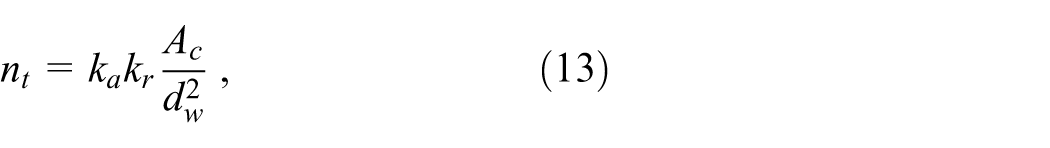
where d w is the wire diameter and A c is the cross-sectional area of the coil, geometrically determined by the product of the coil width w c and height h c .
Design optimization
Following the quasi-static analysis developed in Section 2, a design optimization of the axial comb-shaped channel MRTFD is performed to compromise multiple competing design objectives. A primary goal is to enhance the richness of tactile interaction by enabling a wide spectrum of perceivable torque feedback levels. This requirement is quantitatively characterized by the dynamic range D r , defined as the ratio between the maximum achievable feedback torque T fb and the corresponding off-state torque T 0 . Moreover, minimizing the energy consumption N is of critical importance for practical feedback applications, as it contributes to higher energy efficiency and reduces undesirable thermal buildup during operation. Another important consideration concerns the upper controllable limit of the feedback torque T fb , which must be sufficiently high to deliver clear and perceivable tactile cues to the driver. Nevertheless, pursuing excessively large maximum torque levels is associated with two notable drawbacks. First, stronger magnetic excitation generally necessitates increased structural dimensions, which in turn raise the off-state torque through enhanced viscous drag and mechanical friction, thereby reducing the achievable dynamic range D r . Second, elevated levels of both maximum and zero-field torque can induce premature driver fatigue, regardless of whether the device is fully energized or operating in the off-state. Accordingly, in the present optimization framework, the maximum controllable feedback torque T fb.max is constrained within a prescribed range that satisfies perceptual requirements while avoiding adverse ergonomic effects.
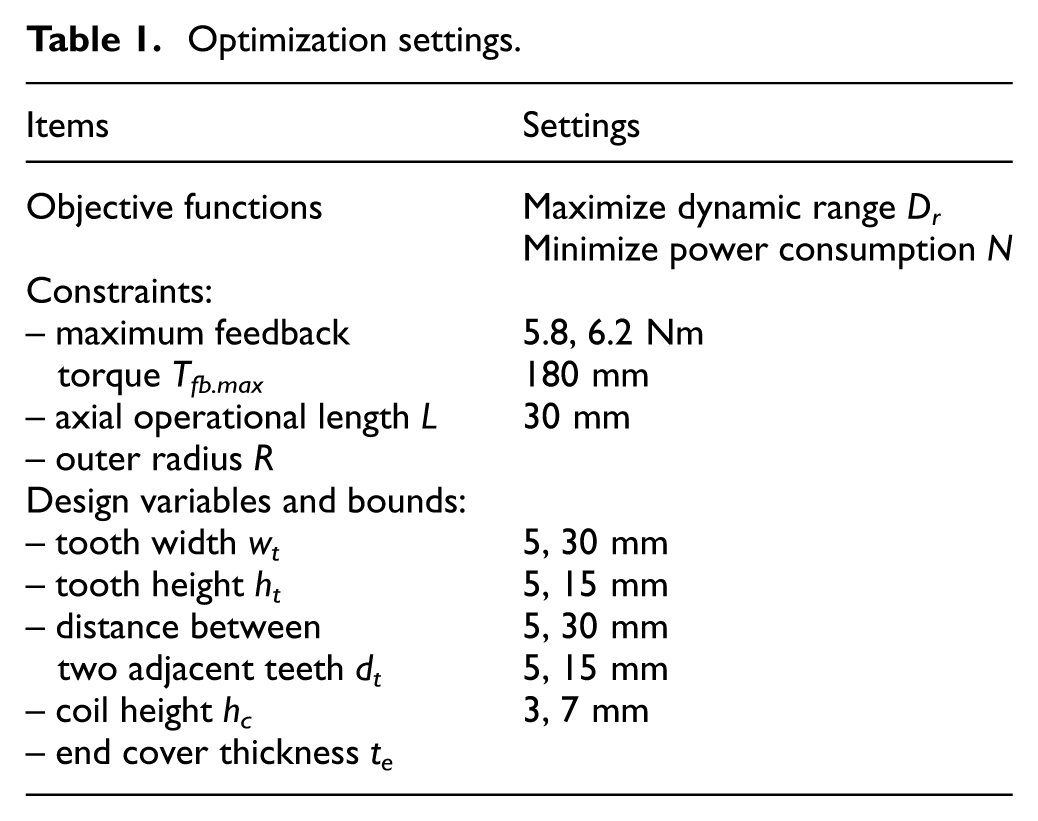
In summary, the design optimization of the proposed MRTFD is posed as a constrained multi-objective optimization problem, which can be stated as follows: Determine an appropriate set of design variables that maximizes the dynamic range Dr and minimizes the energy consumption N, subject to the constraint that the maximum feedback torque Tfb.max remains within a prescribed range (Tfb.L, Tfb.U).
The decision variables in the optimization process consist of the key geometric parameters that govern the configuration of the MRF active regions within the MRTFD, and are specified as follows: the width w t and height h t of the comb tooth, the distance between two adjacent teeth d t , the height of each coil h c , and the thickness of the end cover t e , as shown in Figure 2. The other parameters, such as the radii of the tooth crest r crest and tooth root r root , the width of each coil w c , the thickness of the housing t h , as well as the overall length L and outer radius R of the MRTFD, can be readily derived from the corresponding geometric relationships. It should be noted that, throughout the optimization process, reducing the thickness of the MRF gap t g is generally favorable, as narrower gaps intensify the magnetic field strength and thereby enhance the maximum achievable feedback torque. Similarly, minimizing the thickness of the thin wall t w promotes rapid magnetic saturation in these regions, which facilitates more effective redirection of magnetic flux into the MRF channel segments and improves overall magnetic efficiency. Nonetheless, overly small values of t g and t w pose considerable fabrication difficulties, particularly in terms of dimensional control and structural robustness. Consequently, these parameters are excluded from the set of optimization variables and are instead assigned fixed values of 1 mm based on practical manufacturing considerations.
Numerical modeling and design optimization of the axial comb-shaped channel MRTFD are carried out within the ANSYS Mechanical APDL environment using a finite element method (FEM) framework. The magnetic field response is evaluated through a 2D axisymmetric electromagnetic model employing PLANE233 elements, which enables reliable prediction of the magnetic flux paths and field intensity inside the MRF active channel segments. To address the nonlinear and competing nature of the design objectives, the built-in Multi-Objective Genetic Algorithm (MOGA) in ANSYS is adopted, through which the key geometric parameters of the proposed MRTFD are iteratively updated to obtain a favorable trade-off among the performance criteria defined earlier. The computational domain of the device is restricted to a cylindrical envelope with an axial length of 180 mm and a radius of 30 mm. Preliminary experiments indicated that maintaining a continuous torque of approximately 2 Nm already causes noticeable hand fatigue. Considering that steering operation typically utilizes about one-third of the total steering angle in one direction, the maximum feedback torque T fb.max is set to approximately three times this continuous level, that is, 6 Nm. To provide flexibility in the optimization process and facilitate the identification of feasible solutions, a tolerance of ±0.2 Nm was introduced for the maximum feedback torque, resulting in a constraint range of (5.8, 6.2) Nm. The optimization settings are summarized in Table 1. All ferromagnetic parts are fabricated from C45 steel, whereas the non-magnetic shaft is made of stainless steel. The excitation coils are wound using 24-gage copper wire with an effective diameter of 0.56 mm. The magnetic properties of C45 steel and MRF-132DG are shown in Figure 3. Beyond the abovementioned continuous geometric design variables, the number of excitation coils N c , which also corresponds to the number of comb teeth, is treated as an essential configuration parameter. This discrete variable directly influences the segmentation of the MRF active regions and significantly influences the axial distribution of the magnetic field. Accordingly, multiple MRTFD configurations with different values of N c are investigated and compared to determine an effective coil–tooth arrangement that enhances magnetic utilization and overall output performance.
Optimization settings.
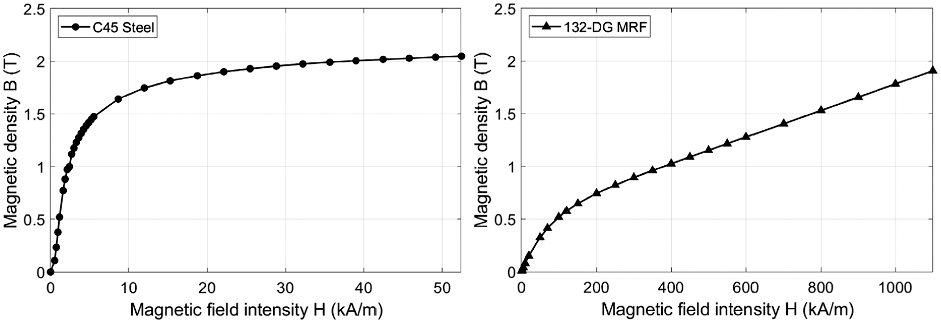
Magnetic properties of C45 steel and MRF-132DG.
Results and discussions
Optimal simulation results
To further elucidate the influence of the coil–tooth number on the optimization outcomes, the simulation results corresponding to different comb-shaped channel MRTFD configurations are examined in this section. Figure 4 presents the Pareto-optimal solution sets obtained for three MRTFD designs with the number of excitation coils N c varying from 6 to 8, highlighting the inherent trade-off between the dynamic range D r and the energy consumption N. It is noted that configurations with fewer than six coils were found to be incapable of achieving the prescribed maximum feedback torque T fb.max , owing to insufficient activation of the MRF operating regions. Conversely, when the number of coils exceeds eight, the available space for each coil and its associated magnetic pole becomes overly restricted, resulting in reduced magnetic excitation efficiency and consequently an inability to adequately activate the MRF to reach the target torque level. For these reasons, such configurations are not presented in the Pareto-front results.
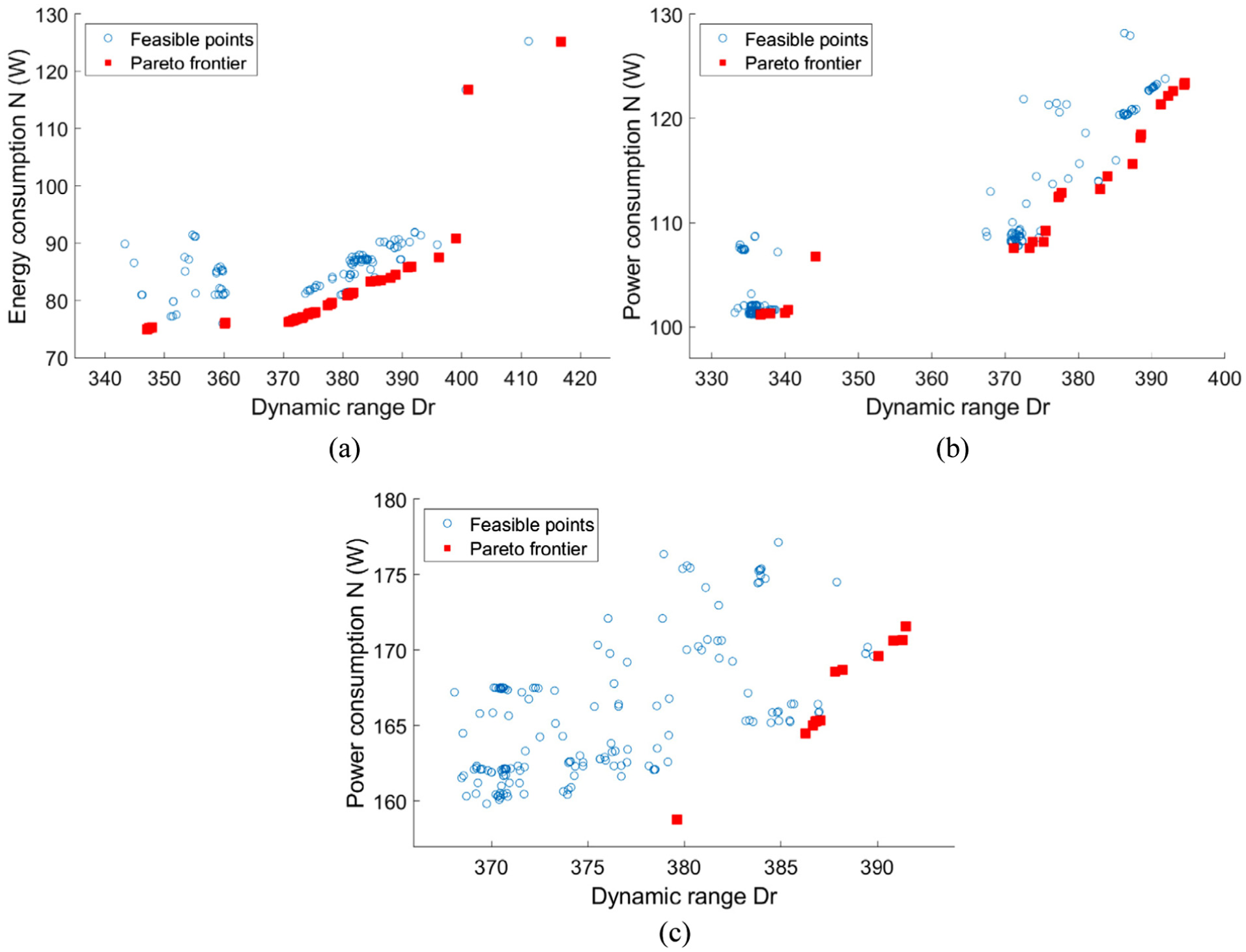
Pareto front charts generated for different configurations of the MRTFD: (a) Nc = 6, (b) Nc = 7, and (c) Nc = 8.
To enable a quantitative comparison among the Pareto-optimal candidates associated with the considered configurations, a scalarized objective function SC is introduced and defined as:
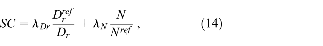
where λ Dr and λ N are the weighting coefficients associated with the dynamic range and energy consumption, respectively, subject to the condition λ Dr + λ N = 1. The superscript ref refers to the corresponding reference values, selected from the feasible Pareto solution exhibiting the maximum dynamic range. Under this formulation, smaller values of SC indicate superior overall performance. The weighting factors may be adjusted to reflect the priorities of a specific SbW application; however, in the present study, equal importance is assigned to both objectives by setting λ Dr = λ N = 0.5. Based on this criterion, the scalarized objective function values of the Pareto candidates for the three investigated configurations are evaluated and summarized in Figure 5. The results demonstrate that the MRTFD configuration with Nc = 6 achieves the most balanced and favorable performance, as evidenced by the lowest red circle point. Consequently, this configuration is selected for subsequent analysis and development in the following sections.
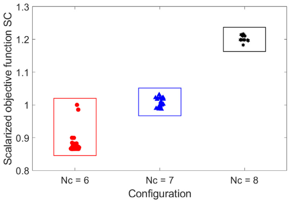
Scalarized objective function values of the Pareto candidate solutions for the three MRTFD configurations.
An insight into the underlying electromagnetic behavior is provided in Figure 6, which depicts the magnetic flux lines and flux density distribution of the optimized axial comb-shaped channel MRTFD with Nc = 6. The results reveal a uniform and concentrated flux penetration within the available MRF domains, allowing a large effective volume of MRF to participate in shear. This enhanced field utilization directly contributes to the improved overall performance achieved through the optimization process.
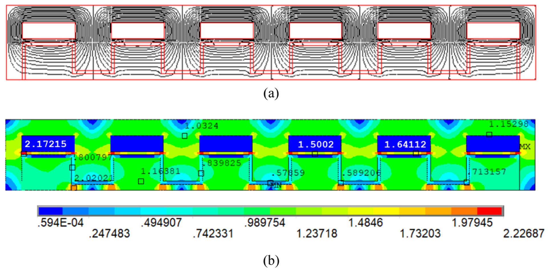
FEM simulation of the optimized axial comb-shaped channel MRTFD: (a) magnetic flux lines and (b) magnetic flux density.
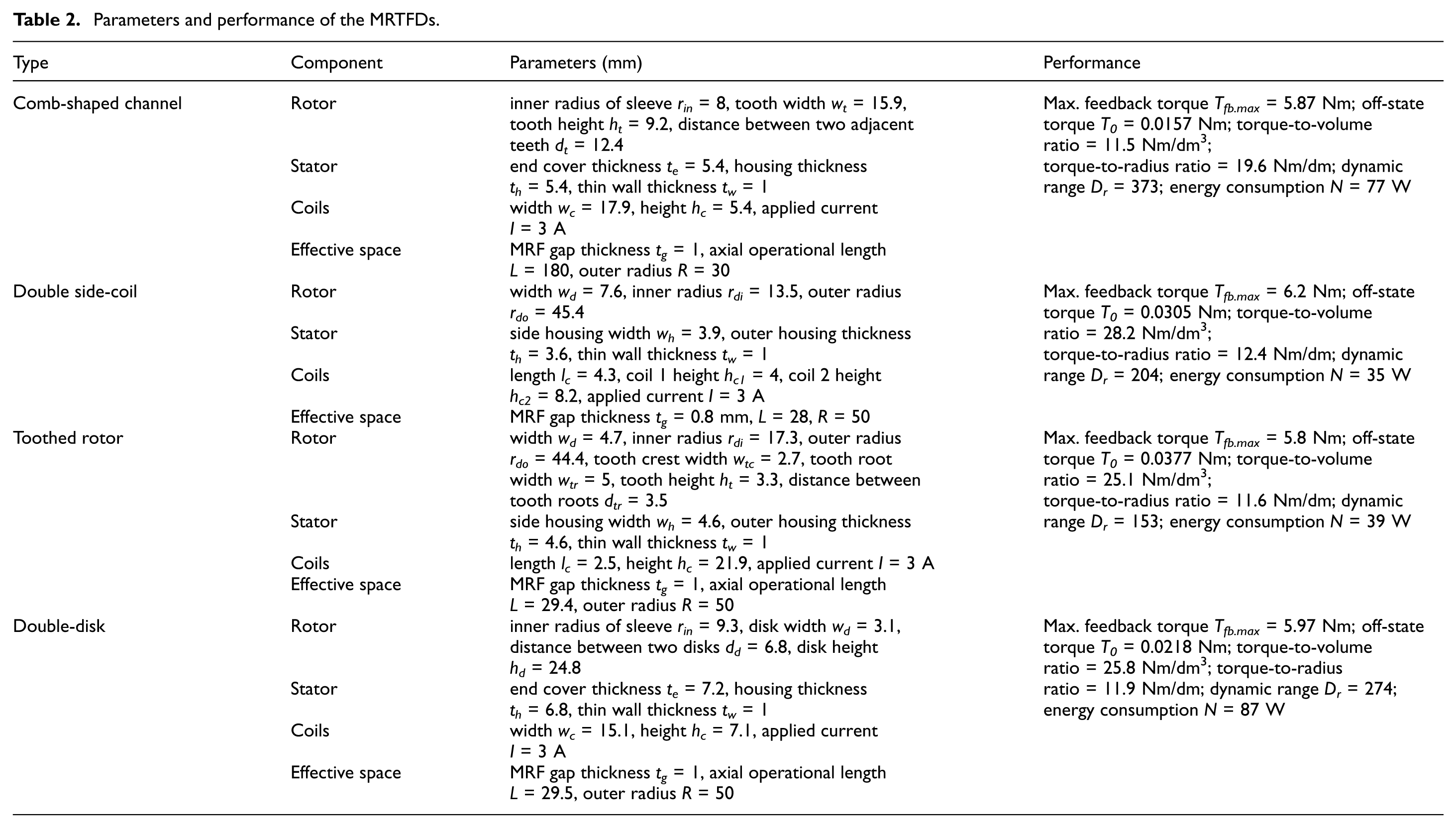
The key geometric parameters and corresponding performance metrics of the optimized MRTFD are compiled in Table 2. To contextualize the advantages of the proposed architecture, optimal solutions from typical disk-type MRTFDs reported in previous studies, including the double side-coil design (Diep et al., 2021; Nguyen et al., 2019), toothed-rotor configuration (Hoang et al., 2024; Nguyen et al., 2022), and double-disk architecture (Hu et al., 2021; Yang et al., 2024) are also presented for reference. The comparison indicates a trade-off among the devices, in which the proposed comb-shaped channel design achieves a markedly wider dynamic torque range despite higher energy consumption than the double side-coil and toothed-rotor designs. This improvement is primarily attributed to its reduced off-state torque, which is only 51%, 42%, and 72% of that of the double side-coil, toothed-rotor, and double-disk designs, respectively, which results from a reduced total shear interface and the associated decrease in viscous resistance under zero-field conditions. It is further noted that, although the double side-coil, toothed-rotor, and double-disk designs benefit from shorter axial length, they require considerably larger outer radius of 50 mm to satisfy the prescribed maximum feedback torque constraint, which would lead to significantly increased rotational inertia and a consequent degradation in the system’s dynamic response. In terms of torque density, despite the lower torque-to-volume ratio of the proposed design due to its greater axial length compared with the other architectures, its torque-to-radius ratio is superior, approximately 1.6 times higher, indicating improved geometric compatibility with diameter-constrained systems. This distinction underscores the differing spatial applicability of the considered architectures: disk-type configurations are better suited to radially unconstrained installations, whereas the elongated and slender structure proposed in this study is particularly advantageous for compact-diameter and space-limited SbW modules.
Parameters and performance of the MRTFDs.
Experiment-based torque validation
In order to verify the reliability of the simulation-based optimization and assess the practical torque-generation capability of the proposed design, an experimental validation study is conducted in this subsection. A physical prototype of the optimized axial comb-shaped channel MRTFD with Nc = 6 is fabricated according to the derived geometric parameters and material specifications. Figure 7 presents the assembled prototype and its principal components, all of which are manufactured using precision CNC machining to ensure accurate realization of the slender cylindrical geometry, the comb-shaped channels, and the associated assembly features.
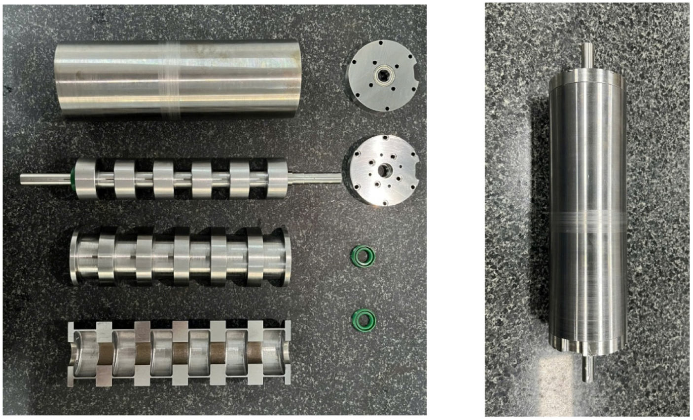
Prototype of the optimized axial comb-shaped channel MRTFD with Nc = 6.
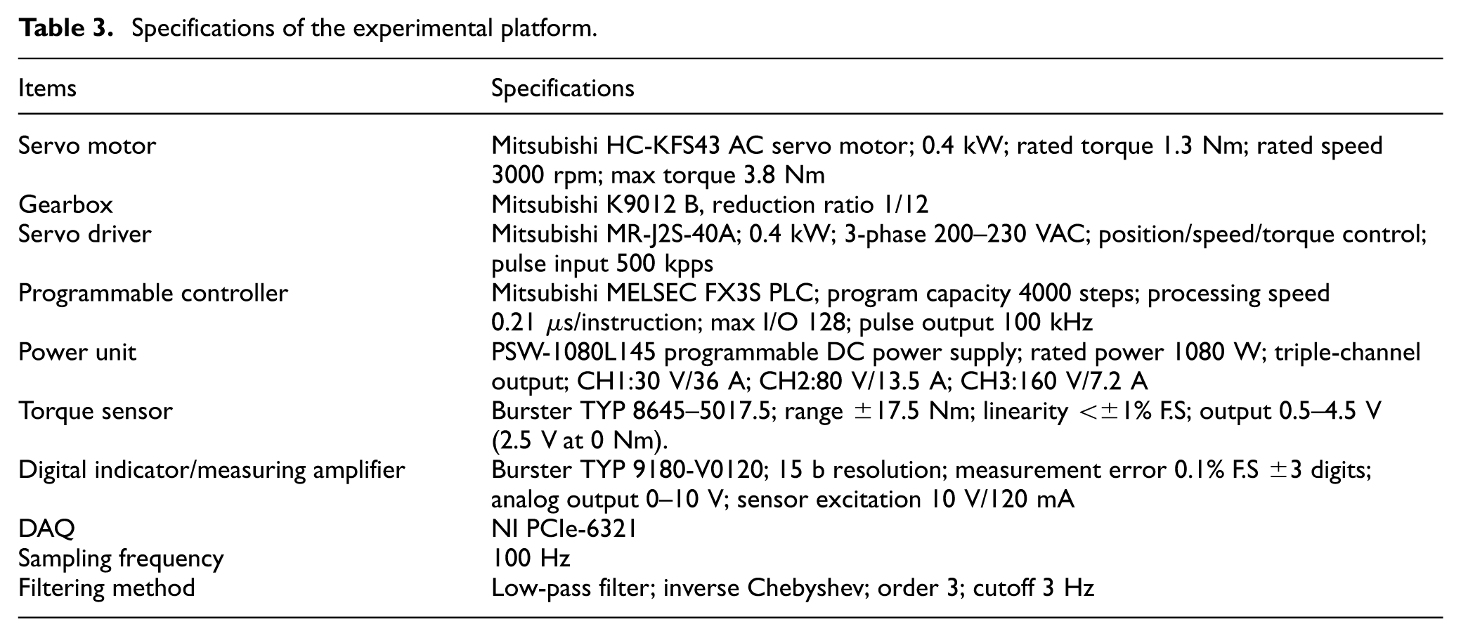
Figure 8 depicts the experimental setup employed to validate the torque output of the fabricated MRTFD prototype. The device under test is mounted coaxially between a servo motor and a torque sensor through precision couplings, while a gearbox is used to provide stable low-speed operation during measurement. The excitation currents supplied to the MRTFD coils are regulated by a programmable power unit and commanded through a computer-based control interface. Torque signals are acquired via a data acquisition (DAQ) system and converted through an A/D converter for real-time monitoring and post-processing. The servo control system ensures precise speed regulation and repeatable operating conditions, enabling reliable evaluation of the torque characteristics of the proposed MRTFD under various excitation levels. The specifications of the experimental platform are summarized in Table 3.
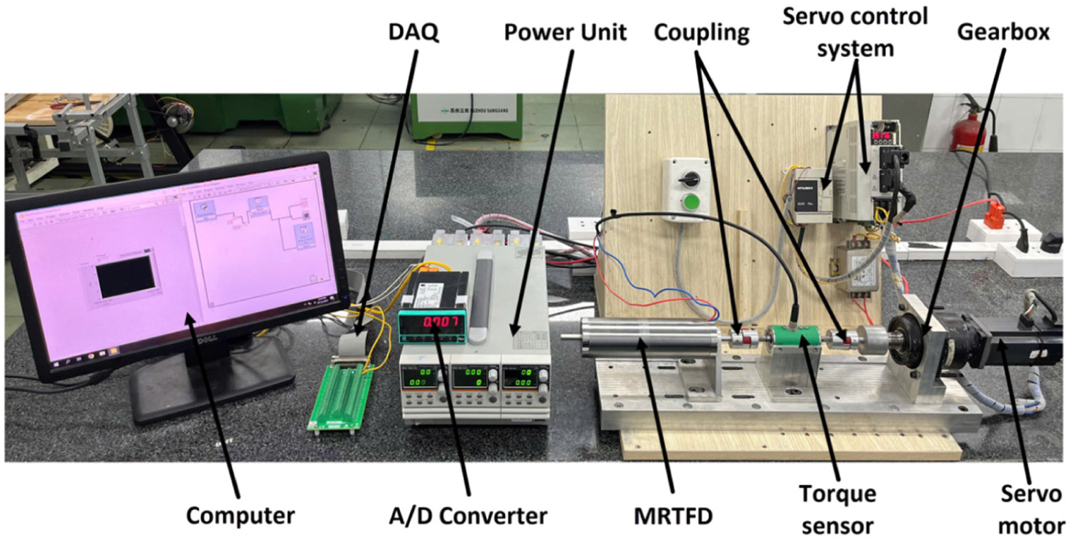
Experimental platform to evaluate torque performance.
Specifications of the experimental platform.
To characterize the torque response of the MRTFD prototype, an experimental procedure was conducted under controlled operating conditions. During the test, the rotor shaft was driven at a constant angular velocity of 120 rpm to ensure stable shear conditions in the MRF. Initially, the MRTFD was kept in the off-state (0 A input current), allowing the baseline torque generated by viscous and mechanical friction to be measured. At t = 0.4 s, the excitation current was supplied to the MRTFD coils, marking the transition from the off-state to the active state. The input current was then varied from 0 to 3 A with an increment of 0.25 A to evaluate the torque response across the full operating range of the MRTFD. For each current level, the excitation was maintained for a sufficient duration so that the output torque could reach and stabilize at its steady-state value. The feedback torque was measured and recorded over time, enabling the transient torque response after activation and the steady-state torque corresponding to each current level to be captured. Figure 9 presents the dynamic response of the fabricated MRTFD prototype during activation and the relationship between coil current and generated torque. It can be observed that the torque characteristics of the MRTFD prototype are in good agreement with the predicted trends, confirming the validity of the proposed design and modeling framework. As shown in Figure 9a, the device exhibits a stable and repeatable torque response under an angular velocity of 120 rpm, with a clear transition from the off-state to the active state once the excitation current is applied. In the off-state, the measured residual torque is approximately 0.073 Nm, which is higher than the simulated value of about 0.06 Nm. This discrepancy can be mainly attributed to factors neglected, idealized or underestimated in the numerical model, such as seal friction, bearing losses, machining tolerances, and the inherent yield stress of the MRF under zero-field conditions. Additionally, slight misalignments in assembly and surface roughness of the shearing interfaces may further contribute to the elevated off-state torque observed experimentally. Upon energization, the torque increases rapidly and reaches a steady level within a short transient period, indicating fast magnetic field establishment and effective activation of the MRF regions. As the applied current is increased from 0 to 3 A, the steady-state torque rises monotonically, as illustrated in Figure 9(b). The experimental torque–current relationship closely follows the modeling results, with only minor deviations at higher current levels. These deviations are likely caused by magnetic saturation in the core material, nonuniform flux distribution, and unintended magnetic flux escaping into the surrounding space. Nevertheless, the prototype is able to achieve a maximum feedback torque of approximately 5.82 Nm at 3 A, which falls within the prescribed target range and satisfies the design requirement for SbW applications. Overall, the experimental findings demonstrate that the optimized axial comb-shaped channel MRTFD can deliver a wide and controllable torque range with good fidelity to the simulation predictions, thereby validating both the proposed architecture and the optimization methodology.
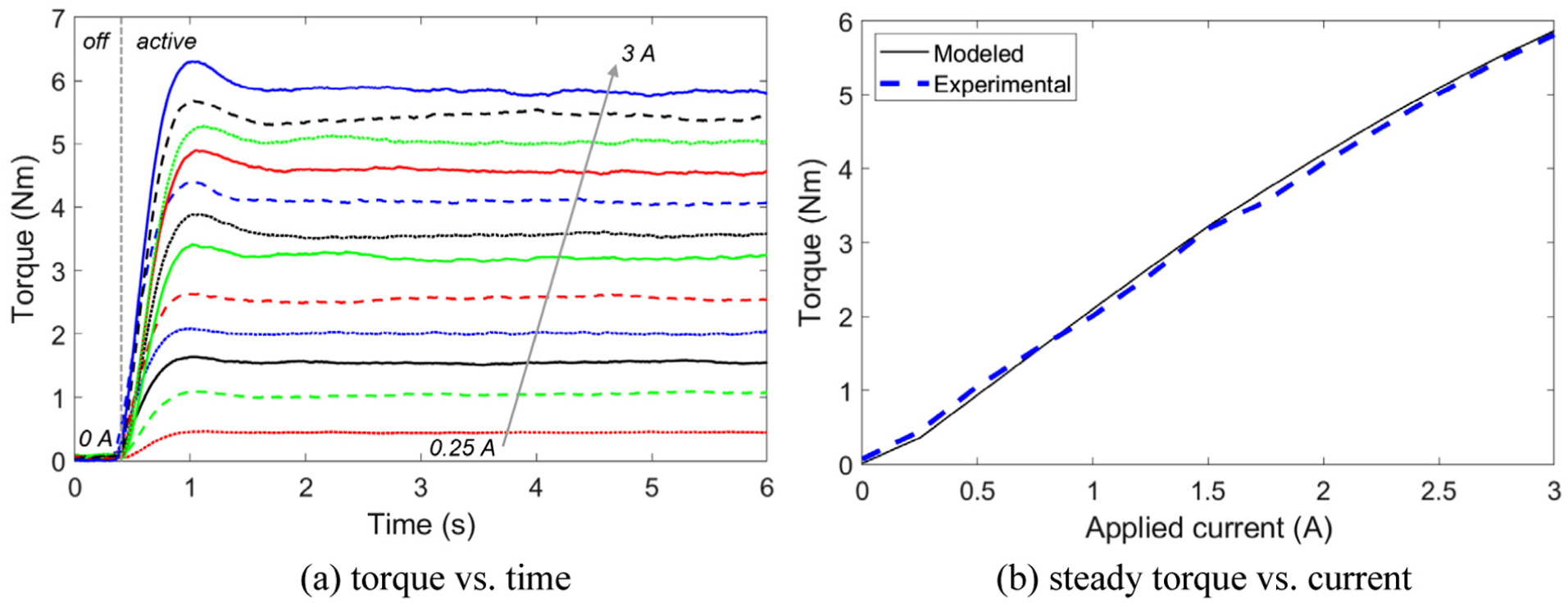
Experimental torque of the MRTFD prototype under different currents of 0–3 A (increment of 0.25 A): (a) torque versus time and (b) steady torque versus current.
Feedback control validation
Since the handwheel is decoupled from the roadwheels, SbW systems inherently lose the intrinsic steering feel that arises from direct mechanical transmission in traditional steering mechanisms. By integrating the axial comb-shaped channel MRTFD into a steering module, the steering feedback can be artificially regenerated. For this system, the governing rotational dynamic equation of the handwheel assembly is established as follows:
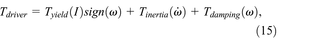
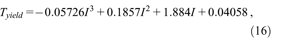
where the handwheel torque T driver perceived by a driver is balanced by the controllable yield torque T yield generated by the MRTFD together with the mechanical transmission dynamics, including the inertial torque T inertia and the viscous damping torque T damping . In the proposed configuration, the yield torque constitutes the dominant component of the overall feedback torque and serves as the main controllable input for shaping the steering feel. Owing to its strong dependence on the applied excitation current, this torque can be adequately described by a torque–current relationship obtained via curve fitting of the experimental data extracted from Figure 9, expressed as:
The inertial contribution originates from the rotational acceleration of the handwheel assembly and is characterized by the equivalent rotational inertia J s , yielding:

The last term, namely the viscous damping torque, accounts for both the inherent viscous behavior of the MRTFD and the parasitic dissipation introduced by mechanical components such as lip seals, bearings, and other rotating interfaces. These combined effects are represented by an equivalent viscous damping coefficient b s , leading to:

In this study, a torque control scheme combining a PID feedback controller with inverse-model feedforward compensation is implemented to validate the feedback control capability of the proposed MRTFD-based steering system, as illustrated in Figure 10. In MR actuators, the relationship between coil current and output torque is highly nonlinear and affected by hysteresis, fluid dynamics, and parameter variations. By introducing an inverse model in the feedforward path, the controller directly estimates the required current corresponding to the desired torque, thereby compensating for the dominant static nonlinearity of the device. This significantly reduces the burden on the feedback loop and improves tracking performance, particularly during rapid torque transitions. The PID controller is then responsible for correcting residual errors caused by modeling inaccuracies, disturbances, and unmodeled dynamics. Compared with purely feedback-based PID control, the proposed feedforward–feedback structure improves response speed and reduces steady-state tracking error without requiring excessively high controller gains. More advanced strategies such as adaptive control, sliding-mode control, or model predictive control could potentially handle nonlinearities and uncertainties more explicitly; however, these methods generally require higher computational cost, more complex tuning procedures, and detailed system identification, which may limit their practicality for real-time implementation in automotive haptic devices. In contrast, the combined PID and inverse feedforward approach offers a favorable trade-off between control performance, robustness, and implementation efficiency, making it well suited for SbW tactile feedback applications where reliable torque rendering, stability, and low-latency response are critical.
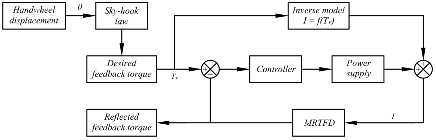
Torque feedback control scheme for the MRTFD-based steering system.
The control framework takes the handwheel angular displacement θ as the input, from which the desired feedback torque T desired is generated using a sky-hook-based strategy as follows:

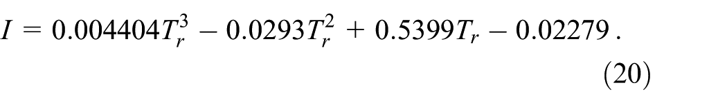
The control gain C s is selected to establish a linear mapping between the handwheel angular displacement and the desired feedback torque, such that θ∈ (−π, π) corresponds to T desired ∈ (−5.75, 5.75) Nm. Under this specification, C s takes a value of 1.8303 Nm/rad. The desired torque T desired is then compared with the measured reflected torque T reflected to produce a tracking error, which is processed by a PID controller to ensure closed-loop stability and robustness against disturbances and modeling uncertainties. In this study, the PID controller parameters were empirically tuned based on the observed transient response and steady-state error of the system, yielding Kp = 74, Ki = 150, Kd = 2.35. In parallel, a feedforward inverse model of the MRTFD is incorporated to compensate for the nonlinear relationship between the applied excitation current and the generated yield torque. This inverse model maps the desired torque directly to the corresponding excitation current I, thereby accelerating the system response and reducing the steady-state tracking error. The inverse current–torque relationship is constructed through curve fitting of the experimental data presented in Figure 9, expressed as:
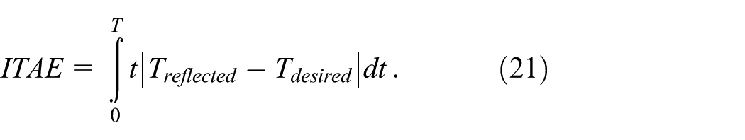
A sensitivity analysis was conducted by varying each PID gain within ±30% of its tuned (nominal) value while keeping the other gains fixed. The controller performance was evaluated using the ITAE (Dorf and Bishop, 2011) and the maximum tracking error e max of the torque response, defined as follows:

As shown in Figure 11, the minimum ITAE occurs near the nominal value of all three gains, suggesting that the experimentally tuned parameters provide favorable tracking performance. Variations in K p and K i lead to only minor changes in both performance indices, while a more noticeable influence on the maximum tracking error e max is observed for variations in K d , which gradually decreases as K d increases. Nevertheless, the change in e max remains very small, with a maximum difference of only about 0.05 Nm compared to the nominal condition. Overall, the results demonstrate that the controller performance remains stable under ±30% parameter variations, indicating the robustness of the tuned PID gains.
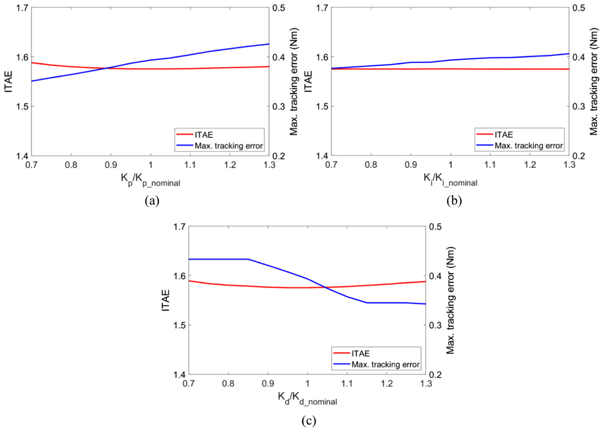
Sensitivity of the controller performance to variations in (a) K p , (b) K i , and (c) K d , measured by ITAE and maximum torque tracking error.
Building upon the proposed control scheme, an experimental validation is conducted to assess the feedback control performance of the MRTFD-based steering system. The experimental setup, illustrated in Figure 12, consists of an SbW test rig incorporating the MRTFD prototype integrated into the steering column. The system includes a steering handwheel driven by a servo motor through a gearbox, a torque sensor mounted inline to measure the reflected feedback torque, and a real-time control platform responsible for signal acquisition and control execution. The MRTFD is supplied by a programmable power unit, while the feedback control algorithm is implemented on a host computer via an DAQ interface.
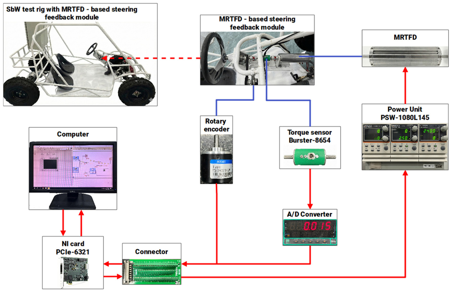
Experimental SbW test rig equipped with the proposed MRTFD-based steering feedback module.
To emulate typical steering maneuvers under normal driving conditions, low-frequency experiments are first carried out at 0.5 Hz. The handwheel angular displacement is prescribed as a sinusoidal waveform spanning from −π to π, thereby covering the general steering range in a continuous and repeatable manner. The corresponding experimental results are presented in Figure 13, where Figure 13(a) depicts the time histories of the desired feedback torque and the measured torque alongside the handwheel angle, while Figure 13(b) illustrates the torque–angle relationship. As observed, the measured feedback torque closely follows the desired torque profile, demonstrating accurate torque tracking across the steering range. However, discrepancies are noticeable in the vicinity of zero torque, where the measured torque cannot fall below a finite threshold due to the inherent off-state torque of the MRTFD. This limitation leads to a slight loss of smoothness around torque reversal but does not compromise the overall control fidelity.
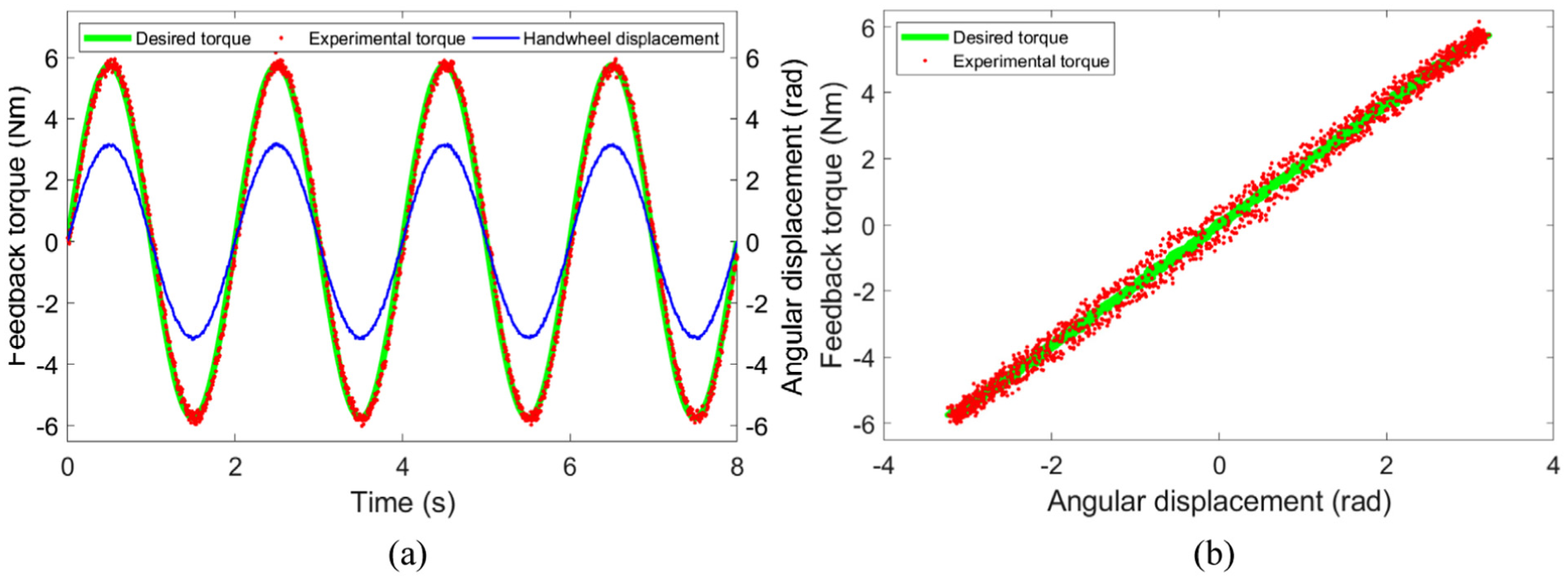
Experimental feedback control results at 0.5 Hz: (a) time histories of handwheel angle and feedback torque and (b) torque–angle relationship comparing desired and measured torques.
The same experimental protocol is subsequently repeated at a higher excitation frequency of 2 Hz to represent rapid steering actions. The corresponding results, shown in Figure 14, indicate that the feedback torque remains well regulated and continues to track the desired reference with acceptable accuracy. Compared to the low-frequency case, a modest degradation in tracking performance is observed, primarily manifested as increased hysteresis in the torque–angle loop and slightly enlarged phase lag. These effects can be attributed to the combined influence of the MRTFD’s magnetization dynamics, current response limitations, and rate-dependent hysteresis of the MRF under fast excitation. Nevertheless, the controller maintains stable and consistent torque rendering throughout the operating range.
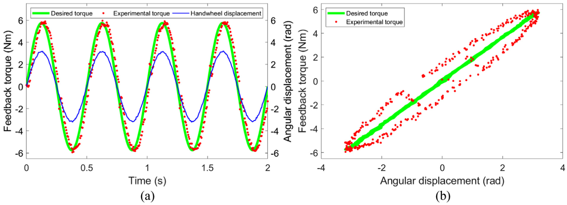
Experimental feedback control results at 2 Hz: (a) time histories of handwheel angle and feedback torque and (b) torque–angle relationship highlighting rate-dependent effects.
Although the experimental results demonstrate satisfactory torque tracking performance of the proposed comb-shaped channel MRTFD, several limitations of the present validation setup should be acknowledged. First, the experiments were conducted under controlled laboratory conditions using prescribed sinusoidal steering inputs rather than realistic road excitation profiles. In practical SbW applications, steering feedback is influenced by complex road disturbances, tire–road interactions, and vehicle dynamics, which may introduce additional transient components not captured in the current setup. Furthermore, the tests were performed at approximately constant ambient temperature. The rheological properties of magnetorheological fluids are known to be temperature-dependent; therefore, extreme thermal environments encountered in real vehicle operation could alter the yield stress, viscosity, and magnetic response of the fluid, potentially affecting torque generation and dynamic response. Additional factors such as long-term material aging, coil heating, and power electronics limitations may also influence the behavior of the device during extended operation.
Despite these limitations, the obtained results provide meaningful insights that can be generalized to broader SbW implementations. The proposed control framework, combining a physics-informed torque model with PID feedback and inverse-model feedforward compensation, does not rely on a specific mechanical scale and can be readily adapted to other MRTFD geometries by recalibrating the model parameters (e.g. yield torque mapping, equivalent inertia, and damping coefficients). Since the desired steering feedback torque is generated through a tunable mapping between angular displacement and target torque, the control structure can be reparametrized to match the steering feel requirements of different vehicle classes, ranging from compact passenger vehicles to heavier platforms. In this sense, the experimental validation primarily demonstrates the feasibility and robustness of the control strategy rather than a single device configuration. With appropriate scaling of actuator capacity, sensor resolution, and parameter identification, the same control scheme can be extended to various SbW systems, supporting practical scalability across different steering mechanisms and vehicle sizes.
Overall, the experimental results confirm that the proposed MRTFD-based steering feedback system, augmented by a PID controller with inverse-model feedforward compensation, is capable of delivering accurate and responsive torque feedback under both normal and aggressive steering conditions. These findings validate the effectiveness of the proposed design and control strategy, thereby providing a solid experimental foundation for the practical implementation of MRTFD-based steering feedback in next-generation SbW systems.
Concluding remarks
This study presented the design, optimization, and experimental validation of a compact MRTFD tailored for SbW applications. An axial comb-shaped channel architecture was proposed to achieve a wide controllable torque range under strict geometric constraints, particularly the elongated form and limited radial space characteristic of SbW steering columns while maintaining a low off-state torque. Comparative simulation results demonstrated that, although the optimized design exhibits a higher energy consumption than typical disk-type MRTFDs reported in the literature, it offers a markedly larger dynamic torque range, representing a deliberate trade-off to enhance the steering feel reproduction.
A prototype of the optimized MRTFD was fabricated and experimentally characterized. Torque measurements under various excitation currents confirmed a strong and monotonic current–torque relationship, with good agreement between modeling and experimental results. Minor discrepancies, particularly in the off-state, were attributed to unmodeled or underestimated factors, magnetic flux leakage, and manufacturing tolerances. The dynamic torque responses further verified the device’s capability to deliver stable and repeatable feedback torque over the prescribed operating range.
Building upon the validated torque characteristics, a feedback control framework integrating a PID controller with an inverse-model feedforward compensation was implemented and experimentally evaluated on an SbW test rig. Low- and high-frequency steering tests demonstrated that the measured feedback torque closely tracks the desired torque, with only limited degradation near zero torque due to the inherent off-state torque of the MRTFD. Overall, the results confirm that the proposed MRTFD and control scheme can effectively regenerate steering feel in SbW systems, thereby reinforcing the practical viability of MRTFD-based torque feedback modules for future SbW systems.
Footnotes
Funding
The authors disclosed receipt of the following financial support for the research, authorship, and/or publication of this article: This research is funded by Vietnam National Foundation for Science and Technology Development (NAFOSTED) under grant number 107.04-2025.60.
Declaration of conflicting interests
The authors declared no potential conflicts of interest with respect to the research, authorship, and/or publication of this article.
Data availability statement
The data that support the findings of this study are available on request from the corresponding author, Q. H. Nguyen, email: