
Abstract
This study investigates the spatiotemporal evolution and dynamic microwave absorption properties of ferrofluid interfaces under lateral confinement and vertical magnetic excitation. We examine the morphological transition of a magnetite-based ferrofluid in a confined cylindrical domain (D = 2 cm) subjected to oscillating magnetic fields (Bmax = 40.5 mT, f = 0–105 Hz). Electromagnetic characterization in the Ku-band (12–18 GHz) was conducted using a metal-backed configuration to explicitly isolate Reflection Loss (RL). Results reveal that microwave absorption is governed by a synergy between bulk dissipation and surface geometry. While static layers exhibit thickness-dependent absorption, dynamic excitation enables an active “geometric enhancement” mechanism. We demonstrate an optimal operational window at low frequencies (f = 15–35 Hz) for thick layers (d≥7 mm), where the stable ferromagnetic soliton functions as a gradient-index impedance matcher. Although the absolute peak RL of −9.46 dB at 17.8 GHz is numerically modest compared to traditional solid-state absorbers, its significance lies in its in-situ, reversible spatial tunability. This dynamic topology minimizes surface reflection and maximizes energy coupling, establishing a design strategy for adaptive electromagnetic absorbers capable of switching their reflection characteristics through precise fluid control.
Keywords
Introduction
Electromagnetic interference (EMI) in the microwave and millimeter-wave bands is becoming a pervasive constraint as high-density electronics, phased-array antennas, and edge-AI sensors are integrated into compact platforms (Hou et al., 2024; Lv et al., 2018; Sun et al., 2019; Zhang et al., 2024). While traditional metal-based shields effectively block electromagnetic waves through reflection, they suffer from fixed geometries, high weight, and the generation of secondary electromagnetic pollution caused by the reflected radiation (Barani et al., 2020; Duan et al., 2018; Fei et al., 2020; Sambyal et al., 2018). Consequently, recent research has pivoted toward “absorption-dominant” materials that dissipate incident energy rather than redirecting it (Ryu et al., 2022). As highlighted in the report, the ideal EMI shield should possess a low reflection coefficient and a gradient-impedance structure to maximize the entry of electromagnetic waves into the absorbing medium (Xue et al., 2023). Modern research has shifted toward the development of smart or broadband microwave absorbers and proposed innovative materials that not only attenuate incident waves through dielectric or magnetic dissipation but also provide tunable electromagnetic interference shielding effectiveness, allowing them to adapt to broadband electromagnetic environments (Lim et al., 2025; Pang et al., 2018; Varshney et al., 2014; Wu et al., 2024; Zhang et al., 2017).
Another promising route to achieve this balance is to use magnetically responsive media whose electromagnetic parameters and surface topology can be reconfigured in situ, enabling tunable impedance matching and broadband loss without permanently fixed microstructures (Malaescu et al., 2024).
Ferrofluids offer a distinctive pathway toward intelligent, field-programmable EMI mitigation because both their effective electromagnetic parameters and their geometry can be controlled by an external magnetic field (Barala et al., 2013; Kuan et al., 2023). Previous studies have established that the microwave absorption of ferrofluids is governed by the complex permeability of the magnetic nanoparticles and the dielectric properties of the carrier fluid (Malaescu et al., 2024). However, the majority of these investigations have focused on quiescent layers or polymer-encapsulated composites (Varshney et al., 2014).
When a ferrofluid layer is subjected to a perpendicular magnetic field exceeding a critical threshold, it undergoes a morphological transition known as the Rosensweig instability (Cowley and Rosensweig, 1967). In infinite domains, this instability naturally selects a hexagonal lattice with a critical wavelength determined by the balance of magnetic traction and surface tension. However, practical applications often require fluid containment within finite geometries. Lateral confinement imposes boundary conditions that disrupt the natural lattice, forcing the system into discrete, quantized modes (Gollwitzer et al., 2006; Pervin et al., 2025; Spyropoulos et al., 2019). Under these restrictive boundary conditions, the fluid instead forms Ferromagnetic Solitons, defined in this study as isolated, single fluid spikes resulting from the geometrically constrained Rosensweig instability. The geometry of these ferromagnetic solitons is of particular interest for EMI mitigation. A tall, conical fluid spike effectively functions as a gradient-index structure, minimizing impedance mismatch at the air-fluid interface and enhancing the coupling of incident waves into the absorbing bulk (Varshney et al., 2014). Yet, the dynamic control of these structures under oscillating fields remains a complex hydrodynamic problem involving the interplay of fluid inertia, viscous dissipation, and magnetic driving forces.
Unlike prior works that primarily evaluate transmission-based shielding effectiveness (SE) in unbacked fluids, this study explicitly utilizes a metal-backed configuration to isolate and evaluate Reflection Loss (RL; Xie et al., 2020). In this regime, the absorption mechanism fundamentally relies on the ferromagnetic soliton functioning as a gradient-index impedance matcher (Liu et al., 2015; Maosheng et al., 2003; Meng et al., 2009). The tapered conical geometry provides a smooth impedance transition (Zin) from free space into the highly lossy bulk fluid, effectively bridging the dielectric mismatch (Kim et al., 1993). This topological feature suppresses direct specular reflection at the air-fluid interface, forcing the incident waves to penetrate deeper into the bulk medium where they are continuously dissipated via the dielectric and magnetic losses of the suspended nanoparticles.
In this study, we investigate the dynamically tunable microwave absorption properties of a laterally confined ferrofluid subjected to vertical magnetic excitation. We demonstrate that by manipulating the initial layer thickness and oscillation frequency, the system can be driven into a “geometric enhancement” regime characterized by the formation of a single, stable ferromagnetic soliton. These findings establish the ferromagnetic soliton as a practical platform for adaptive electromagnetic interference (EMI) mitigation, particularly in compact enclosures where absorption performance can be actively tuned through the interplay of fluid inertia and magnetic excitation.
Experimental setup and methodology
The experiments utilized a commercially available oil-based ferrofluid (EMG 905, Ferrotec Corp.), which consists of nanoscale magnetite (Fe3O4) particles dispersed in a hydrotreated light petroleum distillate carrier, stabilized by an oleic acid surfactant. The fluid possesses a magnetic particle concentration of approximately 7.8% by volume. Key physical properties include a saturation magnetization of Ms=44 mT, a bulk density of ρ=1200 kg/m3, viscosity η=0.005 Pa·s, and a surface tension of σ = 25.6 mN/m.
To investigate the effects of lateral confinement and layer depth on ferromagnetic soliton formation, the ferrofluid was dispensed into Petri dishes with diameters of 5 cm (unconfined control) and 2 cm (confined test case). Precise volumes were used to establish four distinct layer thicknesses: d = 3, 5, 7, and 9 mm. These variations allowed for a systematic evaluation of how fluid volume affects both the hydrodynamic instability and the bulk electromagnetic absorption.
To ensure consistent magnetic excitation across varying fluid layer thicknesses (d = 3–9 mm), the applied magnetic field was calibrated to a maximum flux density of Bmax = 40.5 mT at the bottom of the Petri dish. Because the ferrofluid operates in a near-magnetically saturated state (Ms ≈ 44 mT), its differential relative permeability approaches that of free space (μr ≈ 1). Consequently, the fluid medium itself does not significantly attenuate or distort the applied magnetic field.
Although the magnetic field strength naturally decays with vertical distance from the coil, our experimental protocol actively accounted for this spatial variation. Rather than applying a constant coil current across all trials, we calibrated the power supply for each individual sample. This ensured that a consistent maximum magnetic flux density (Bmax = 40.5 mT) was maintained precisely at the vertical center of the fluid layer, regardless of its respective thickness.
A dynamic, vertically oscillating magnetic field was generated using a custom-wound air-core solenoid placed directly beneath the sample holder. The coil was driven by a programmable AC power supply (GW Instek ASR-2100), enabling precise control over the field frequency (f) and amplitude. The magnetic flux density (B) at the center of the fluid layer was calibrated and monitored using a Hall probe Gaussmeter (F.W. Bell 5180) to ensure field uniformity across the sample domain.
The EMI Reflection Loss (RL) was characterized within a customized anechoic shielding box with internal dimensions of 100 cm × 100 cm × 100 cm. The inner walls were lined with pyramidal microwave absorbers to minimize internal reflections and isolate the sample from environmental noise, as shown in Figure 1. A pair of linearly polarized horn antennas was positioned to transmit and receive signals through the ferrofluid sample. These antennas were connected to a Vector Network Analyzer (Rohde & Schwarz ZNB40), which operated in the Ku-band frequency range (12–18 GHz).
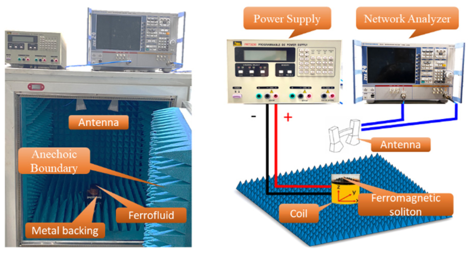
Schematic of the experimental apparatus for dynamic ferromagnetic soliton characterization and EMI shielding measurement.
As illustrated in Figure 1, the magnetic excitation coil is positioned directly beneath the Petri dish. In this configuration, the metallic coil assembly functions as a Perfect Electric Conductor (PEC) boundary. This PEC boundary condition guarantees zero microwave transmission (S21 = 0), thereby strictly isolating the electromagnetic interaction to surface reflection (S11) and bulk absorption within the fluid. Consequently, the shielding characterization of this work focuses on the Reflection Loss (RL) rather than the transmission-based shielding effectiveness. Accordingly, the reflection loss (RL) of a metal-backed single absorb layer can be expressed as (Liu et al., 2015; Xie et al., 2020):
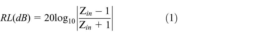
Here, Zin represents the input impedance of the absorber. The variables μr and εr correspond to the relative permeability and permittivity of the absorbing material, respectively. The f is the frequency of the incident wave, c is the propagation velocity of light in a vacuum, and d represents the physical thickness of the absorber. In this work, the measurement quantifies the material’s ability to act as a microwave absorber. A lower (more negative) RL value indicates that the incident wave is effectively coupled into the ferrofluid layer, where the conical geometry of the ferromagnetic soliton induces multiple scattering and internal reflections that extend the propagation path.
Results and discussion
Spatiotemporal evolution of ferrofluid instability patterns in oscillating magnetic fields
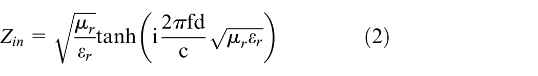
Figure 2 illustrates the time-dependent morphological evolution of the ferrofluid interface under a vertical sinusoidal magnetic field B(t) = Bmax·sin(2πft), with Bmax = 40.5 mT and frequency f = 1 Hz. As shown in Figure 2, the ferrofluid in the 5 cm diameter container approximates an unbounded system relative to the instability wavelength. The surface dynamics exhibit a clear periodicity synchronized with the driving field, which can be categorized into three phases:
Growth Phase (0 s < t < 0.26 s): As the magnetic induction increases, the normal magnetic traction overcomes the stabilizing forces of gravity and surface tension. The surface transitions from a flat state to a hexagonal scattering of peaks. The crest count (N) rises sharply, peaking at N = 103 at t = 0.26 s (approximately T/4), coinciding with the maximum field amplitude.
Relaxation Phase (0.26 s < t < 0.50 s): As the field intensity acts against the restorative forces, the pattern undergoes relaxation. Interestingly, the system does not return immediately to a smooth state; at t = 0.50 s (the zero-crossing point of the AC field), a residual structure of N = 12 “insignificant” spikes remains. This behavior suggests a hydrodynamic hysteresis or viscous delay, where the fluid relaxation time exceeds the rate of field decay.
Cyclic Symmetry: The process repeats in the second half-period (0.5 s < t < 1.0 s), confirming that the dynamic magnetic field can actively manipulate the scattering cross-section of the fluid surface - a critical parameter for adaptive EMI shielding.
Time-resolved morphological evolution of a 3 mm thick ferrofluid layer in a 5 cm diameter Petri dish subjected to a vertical sinusoidal magnetic field (Bmax = 40.5 mT, f = 1 Hz) over one oscillation period.
The observed hydrodynamic hysteresis can be quantitatively validated by comparing the characteristic timescales of the system. The physical response of the ferrofluid is governed by its viscous relaxation time τv, which can be approximated as
Impact of lateral confinement on dynamic ferrofluid instability
The Rosensweig instability possesses a characteristic critical wavelength, defined as
As shown in Figure 3, a closer examination of the high-field interval (0.13 s < t < 0.38 s and 0.63 s < t < 0.88 s) reveals a complex secondary dynamic. The emergence of minute splitting events surrounding the central, dominant crests. These “satellite” peaks represent a frustrated attempt by the fluid to access its natural, higher-wavenumber state (as seen in the 5 cm dish). While the global confinement forces the fluid into a low-order mode (fewer, larger peaks), the local magnetic flux density at the tips of these enlarged crests is extremely high. This local stress momentarily exceeds the threshold for instability, triggering partial splitting. However, due to the lack of lateral space, these secondary peaks cannot fully mature, resulting in transient, tiny formations around the primary ferromagnetic peaks.
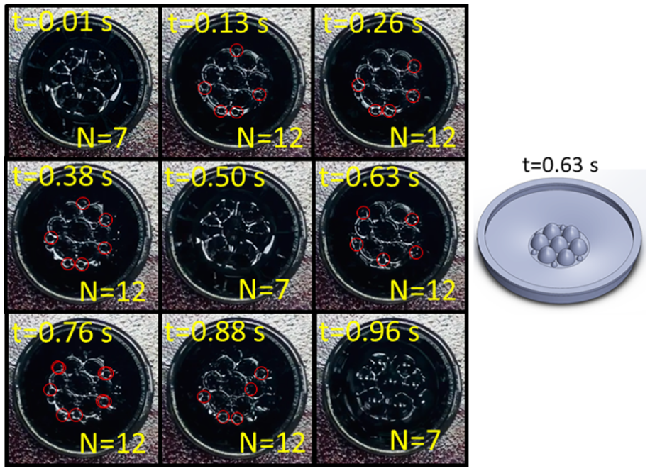
Time-resolved morphological evolution of a 3 mm thick ferrofluid layer in a 2 cm diameter Petri dish subjected to a vertical sinusoidal magnetic field (Bmax = 40.5 mT, f = 1 Hz) over one oscillation period.
Furthermore, the meniscus formed at the container wall introduces capillary forces that suppress small-scale corrugations near the perimeter (as shown in the red circle in Figure 3). To minimize total surface energy within the confined volume, the fluid self-organizes into fewer, volumetrically larger crests. This “coarsening” effect results in ferromagnetic peaks with larger individual amplitudes but lower spatial frequency compared to the unconfined case.
This geometric tunability has significant implications for the shielding of the material. In the large domain (Figure 2), the high-density array of smaller peaks likely acts as a diffractive surface for Ku-band frequencies, enhancing scattering. Conversely, the confined, large-amplitude peaks (Figure 3) may offer different absorption characteristics due to the increased localized fluid thickness. This demonstrates that boundary constraints are as critical as magnetic field strength in designing adaptive ferrofluid-based EMI shields.
Tunable ferromagnetic soliton formation: The interplay of layer thickness and field frequency
Figure 4 illustrates the sequential morphological evolution of the ferrofluid interface in a 2 cm Petri dish, mapping the critical dependency of ferromagnetic solitons formation on layer thickness (d) and field frequency (f). In the thin layer regime (d = 3 mm), shown in Figure 4(a), the surface exhibits a multi-peak scattering pattern. A clear inverse relationship is observed between frequency and crest density: as the frequency increases from 15 to 105 Hz, the number of spikes (N) decreases monotonically from 8 to 3. In this highly viscous, confined ferrofluid system, the increase in frequency likely raises the energy threshold required to maintain multiple small interfaces. Consequently, the system minimizes energy by “coarsening”—merging smaller peaks into fewer, larger structures—though the limited fluid volume in the 3 mm layer prevents the complete coalescence into a single ferromagnetic soliton.
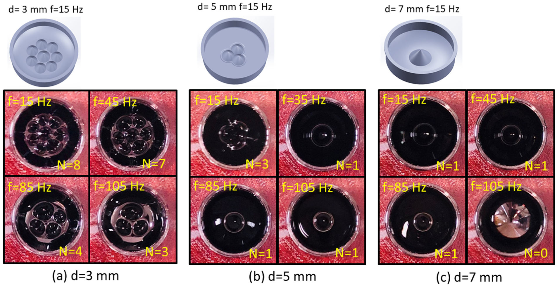
Phase diagram of the ferrofluid surface morphology within a laterally confined domain (D = 2 cm) as a function of initial layer thickness (d) and magnetic oscillation frequency (f): (a) at a shallow depth (d = 3 mm), the crest number (N) inversely correlates with frequency, decreasing from N = 8 to N = 3 without coalescing into a single peak, (b) at an intermediate depth (d = 5 mm), the fluid successfully transitions into a single, stable ferromagnetic soliton (N = 1) at frequencies f ≥ 35 Hz, (c) in a deep layer (d = 7 mm), the single soliton forms readily across low to moderate frequencies (15–85 Hz) but collapses into a flat state (N = 0) at 105 Hz due to inertial phase lag.
As the layer thickness increases to d = 5 mm (Figure 4(b)), the number of the spikes is further decreased compared to the same field conditions in Figure 4(a). At f = 15 Hz, the system is in a transitional state (N = 3). Upon increasing the frequency to the 35–105 Hz range, the discrete peaks merge into a single, high-amplitude structure (N = 1), resulting in the soliton formation. This state, referred to as a ferromagnetic soliton, represents a stable, localized concentration of magnetic energy and fluid mass. The stability of the soliton across this wide frequency band suggests that 5 mm is the least thickness of the ferrofluid layer to the ferromagnetic soliton formation.
In the deep layer regime (d = 7 mm), shown in Figure 4(c), the fluid dynamics are governed by the significant inertial mass of the ferrofluid column. Unlike the thinner layers, where the fluid mass is low enough to follow the driving field into complex, high-wavenumber patterns, the 7 mm layer represents a “heavier” mechanical load. The number of the spikes is further decreased compared to the same field conditions in Figure 4(a) and (b). Apparently, the single ferromagnetic soliton forms readily even at a low frequency of 15 Hz. In particular, a distinct cutoff phenomenon is observed at f = 105 Hz, where the pattern vanishes completely (N = 0), returning to a quasi-flat interface. This suppression is attributed to the hydrodynamic phase lag. While the superparamagnetic nanoparticles respond almost instantaneously to the magnetic field, the macroscopic fluid motion is governed by viscosity and inertia. At high frequencies (105 Hz) and greater depths (7 mm), the inertial mass of the fluid column is too large to oscillate in sync with the driving field. The fluid surface cannot mechanically respond fast enough to the rapid field reversals, leading to a “time-averaged” flattening effect where the instability is effectively damped out. This evolution demonstrates that layer thickness dictates the available fluid volume for peak growth, while frequency acts as a mode selector for the instability pattern.
Parametric control of ferromagnetic soliton amplitude and stability
Figure 5 presents a systematic characterization of the ferromagnetic soliton geometry, correlating the vertical crest extension (h) with the governing parameters of oscillation frequency (f) and layer depth (d). A distinct dependency is observed regarding the onset frequency required to generate a single, stable ferromagnetic soliton. In the thinner 5 mm layer, the fluid column possesses lower inertial mass, allowing it to respond rapidly to the magnetic drive. Consequently, at low frequencies, the fluid retains enough mobility to support multiple competing peaks. A single ferromagnetic soliton only emerges when the frequency is increased to f = 35 Hz. At this higher rate, the hydrodynamic phase lag and viscous dissipation at the boundaries become significant enough to filter out the higher-order modes, forcing the fluid into the fundamental central mode.
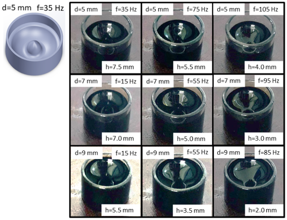
Side-view profiles of the ferromagnetic soliton formation illustrating the dependence of peak height (h) on oscillation frequency (f) and initial layer thickness (d).
In contrast, the thicker layers (d = 7 and 9 mm) represent a significantly heavier inertial load. This increased mass induces substantial hydrodynamic lag even at a low driving frequency of 15 Hz. The fluid is mechanically unable to sustain rapid, small-scale corrugations; therefore, the system naturally selects the single ferromagnetic soliton state immediately, without requiring high-frequency suppression.
Furthermore, the maximum achievable height is inversely proportional to the layer thickness. As shown in Figure 5, under comparable low-frequency conditions, the spike height decreases from h = 7.5 to h = 5.5 mm. While a thicker layer theoretically provides more fluid volume, it also increases the effective mass that the magnetic force must lift against gravity. The magnetic traction acting on the surface must drag a deeper, heavier column of viscous fluid. This increased inertial loading dampens the vertical response, resulting in more rounded, sluggish, and shorter ferromagnetic solitons in deep layers compared to the sharp, tall peaks observed in thinner layers.
These results indicate a trade-off for shielding applications: while thicker layers form stable solitons more easily (at lower frequencies), they produce shorter peaks. Conversely, thinner layers (d = 5 mm) driven at moderate frequencies (f = 35 Hz) yield the tallest ferromagnetic soliton (h = 7.5 mm), likely offering the most effective aspect ratio for interacting with incident electromagnetic waves.
Baseline reflection loss of quiescent ferrofluid layers in the Ku-band
To establish a baseline for the material’s performance, the EMI reflection loss (RL) of the ferrofluid was characterized in the absence of an external magnetic field. Figure 6 presents the RL spectra across the Ku-band frequency range (12–18 GHz) for layer thicknesses varying from d = 3 to d = 9 mm. The thickest layer (d = 9 mm) exhibits the lowest RL of −8.3 dB, while the d = 7 mm layer follows with a peak of approximately −7.6 dB. Interestingly, the thinner layers (d = 3 and d = 5 mm) exhibit nearly identical peak performance, saturating at approximately −7.2 dB. This saturation arises primarily from insufficient bulk volume rather than impedance mismatch at the surface. The thinner layers simply lack the extended physical propagation path necessary for complete volumetric energy dissipation; consequently, unabsorbed microwave energy easily reaches the metal backing and reflects back into free space, inherently limiting the maximum achievable Reflection Loss.
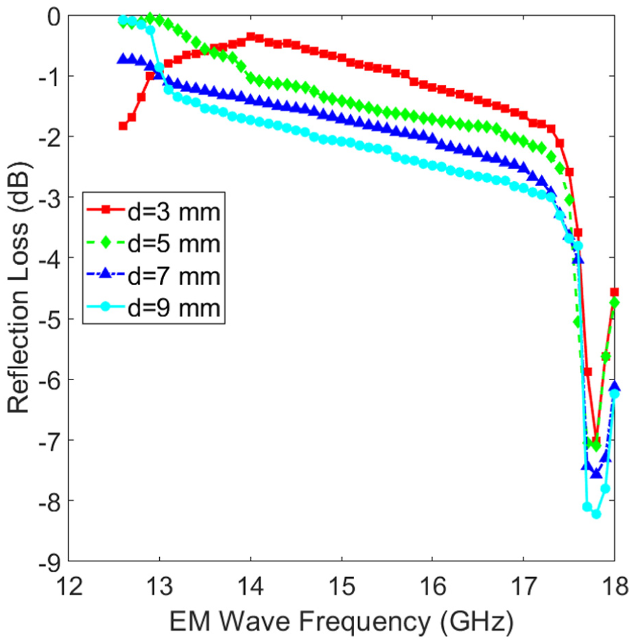
Frequency-dependent electromagnetic interference (EMI) reflection loss (RL) of static ferrofluid layers with varying thicknesses (d = 3–9 mm) in the Ku-band (12–18 GHz).
This trend is consistent with the fundamental principles of microwave propagation in lossy media (Malaescu et al., 2024). As the layer thickness increases from 3 to 9 mm, the physical path length for the electromagnetic wave through the absorbing medium extends. This increases the total interaction volume between the incident wave and the suspended magnetite (Fe3O4) nanoparticles.
Dynamic tuning of reflection loss via ferro soliton topology
To evaluate the active tunability of the shielding performance, the EMI RL was characterized under dynamic conditions using a Vector Network Analyzer (R&S ZNB40). Figure 7 illustrates the RL spectra across the Ku-band for varying ferrofluid layer thicknesses and magnetic field oscillation frequencies. For thinner ferrofluid layers (d = 3 and 5 mm), shown in Figure 7(a) and (b), the shielding performance appears largely insensitive to the dynamic variations of the magnetic field. The peak RL values saturate at approximately −7.10 dB (d = 3 mm) and −7.54 dB (d = 5 mm) at the resonant frequency of 17.8 GHz. These values are statistically comparable to the static baseline (Figure 6). In this regime, the geometric scale of these surface perturbations is insufficient to significantly alter the interaction with the incident Ku-band wavelengths. Consequently, the shielding mechanism remains dominated by the bulk thickness of the layer rather than its surface topology.
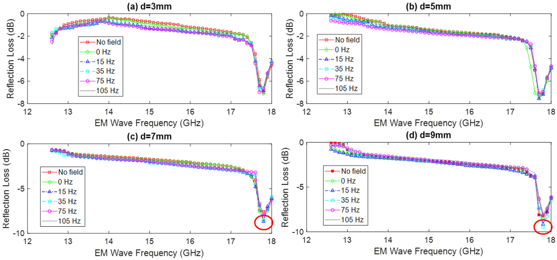
Dynamic EMI reflection loss (RL) spectra of ferrofluid layers under varying magnetic oscillation frequencies (f ≈ 0–105 Hz) in the Ku-band: (a and b) in thinner layers (d = 3 and 5 mm), the RL is dominated by bulk absorption; dynamic surface modulation yields negligible improvement over the static baseline (RL ≈ −7.1∼−7.5 dB), (c and d) in thicker layers (d = 7 and 9 mm), a significant “geometric enhancement” is observed at low frequencies (15–35 Hz).
A distinct transition occurs when the layer thickness is increased to d = 7 and 9 mm (Figure 7(c) and (d)). Here, the RL becomes strongly dependent on the oscillation frequency, revealing an optimal window where fluid depth and surface geometry work synergistically. The highest reflection loss is achieved at low frequencies between 15 and 35 Hz. Specifically, the d = 7 mm layer reaches −8.57 dB, and the d = 9 mm layer peaks at −9.46 dB (highlighted by red circles). It is noted that the formation of a single, tall soliton amplifies the resonant absorption at 17.8 GHz (red circles). However, higher oscillating frequencies (f > 55 Hz) reduce the soliton height, causing the RL to revert toward baseline levels.
It is crucial to note that while the d = 5 mm layer produced the absolute tallest ferromagnetic soliton (h = 7.5 mm, see Figure 5), it did not yield the lowest RL (−7.54 dB). This indicates that soliton height alone is insufficient to guarantee high absorption. Instead, an optimal balance is required: the layer must possess sufficient base thickness to provide substantial bulk absorption, which is then further amplified by the geometric enhancement of the soliton. In the d = 7 and 9 mm cases, the base layer absorbs the majority of the wave energy, while the soliton (h ≈ 5.5–7.0 mm) acts as a gradient-index structure to minimize surface reflections and couple more energy into that deep absorbing layer.
Optimization of ferromagnetic soliton parameters for enhanced EMI shielding
Finally, the experimental data are synthesized to determine the optimal control parameters for minimizing the reflection loss against Ku-band electromagnetic waves. Figure 8 presents a phase map correlating ferromagnetic soliton height (h) with initial layer thickness (d = 5, 7, 9 mm) and oscillation frequency (f = 0–105 Hz). The map defines clear operational boundaries, where h = 0 mm marks two distinct structural failure modes. In thinner layers (d = 5 mm), frequencies below 35 Hz trigger a low-frequency instability; the fluid lacks sufficient viscous damping to support a single peak and breaks into small scatterers. Conversely, in thicker layers (d = 7, 9 mm), frequencies exceeding critical thresholds (105 and 95 Hz, respectively) induce high-frequency collapse, as the inertial phase lag of the heavier fluid entirely prevents vertical growth.
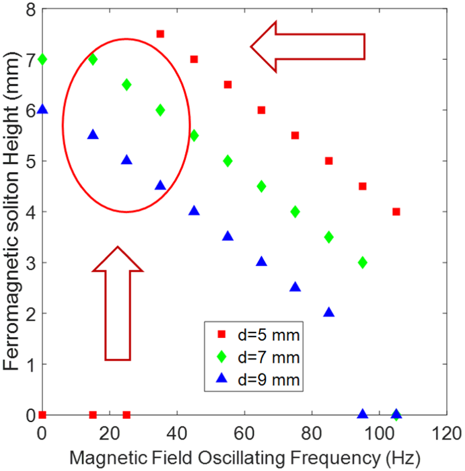
Parametric map of ferromagnetic soliton height (h) as a function of oscillating magnetic field frequency (f) and ferrofluid layer depth (d).
Achieving superior reflection loss requires balancing two competing physical mechanisms: a deep base layer for bulk volumetric absorption and a highly tapered soliton(h ≥ 4.5 mm) for gradient-index impedance matching. The data reveals a fundamental trade-off: while the d = 5 mm layer produces the absolute tallest peaks, it lacks the necessary dissipative volume, whereas the massive d = 9 mm layer provides maximal volume but restricts soliton height due to mass loading. Therefore, optimal geometric enhancement occurs exclusively within d ≥ 7 mm layer driven at 15–35 Hz. This specific regime represents the ideal compromise, sustaining large-amplitude structures that effectively couple incident microwaves into a sufficiently thick absorbing medium without succumbing to inertial collapse.
Conclusions
In conclusion, this study establishes a quantitative framework for adaptive ferrofluid-based microwave absorbers. We define a specific operational window—fluid thicknesses of d ≥ 7 mm driven at low frequencies (f = 15–35 Hz) to reliably trigger an inertial-filtering mechanism that stabilizes a single, high-aspect-ratio ferromagnetic soliton. While the peak Reflection Loss of −9.46 dB is modest compared to optimized static absorbers, the true advantage of this system lies in its dynamic, in-situ tunability and topological reversibility, allowing rapid adaptation to changing electromagnetic environments. Future integration of these liquid-state absorbers into practical, vertically-oriented devices will require addressing physical constraints, such as the gravity-dependent nature of the fluid pools. Overcoming these challenges will likely necessitate advanced conformal encapsulation or porous matrix containment to transition these adaptive mechanisms from horizontal testbeds to versatile aerospace or telecommunication applications.
Supplemental Material
sj-pdf-1-jim-10.1177_1045389X261455726 – Supplemental material for Formation and tunable microwave reflection loss of ferromagnetic solitons in the presence of dynamic magnetic field
Supplemental material, sj-pdf-1-jim-10.1177_1045389X261455726 for Formation and tunable microwave reflection loss of ferromagnetic solitons in the presence of dynamic magnetic field by Hsin-Chieh Hsieh, Huan-Kuang Kuan, Kuei-Ping Feng and Yan-Hom Li in Journal of Intelligent Material Systems and Structures
Footnotes
Funding
The authors disclosed receipt of the following financial support for the research, authorship, and/or publication of this article: The authors thank the National Science and Technology Council of the Republic of China (Taiwan) for financially supporting this study through Grant Nos. NSTC 112-2221-E-606-008 and NSTC 113-2221-E-606 -011 -MY3.
Declaration of conflicting interests
The authors declared no potential conflicts of interest with respect to the research, authorship, and/or publication of this article.
Data availability statement
The raw measurement data supporting the findings of this study are available as Supplementary Material online.
Supplemental material
Supplemental material for this article is available online.
References
Supplementary Material
Please find the following supplemental material available below.
For Open Access articles published under a Creative Commons License, all supplemental material carries the same license as the article it is associated with.
For non-Open Access articles published, all supplemental material carries a non-exclusive license, and permission requests for re-use of supplemental material or any part of supplemental material shall be sent directly to the copyright owner as specified in the copyright notice associated with the article.