
Abstract
Nowadays, sophisticated structures and machinery parts are constructed by using metallic beams. Beams are widely used as structural element in civil, mechanical, naval, and aeronautical engineering. In structures and machinery, one undesirable phenomenon is crack initiation in which the impact cannot be seen overnight. Cracks develop gradually through time that lead finally to catastrophic failure. Therefore, crack should be monitored regularly with more care. This will lead to more effective preventive measure and ensure continuous operation of the structure and machine. Damage in structure alters its dynamic characteristics. The change is characterized by change in modal parameters, that is, modal frequencies. Thus, vibration technique can be suitably used as a nondestructive test for crack detection of component to be tested. Mostly modal frequencies are used for monitoring the crack because modal frequencies are properties of the whole structure component. In this paper, efforts are made to develop suitable methods that can serve as the basis to detection of crack location and crack size from measured axial vibration data. This method is used to address the inverse problem of assessing the crack location and crack size in various beam structure. The method is based on measurement of axial natural frequencies, which are global parameter and can be easily measured from any point on the structure and also indeed, the advantage in modeling complexity. In theoretical analysis, the relationship between the natural frequencies, crack location, and crack size has been developed. For identification of crack location and crack size, it was shown that data on the variation of the first two natural frequencies is sufficient. The experimental analysis is done to verify the practical applicability of the theoretical method developed.
Introduction
Mostly modal frequencies are used for monitoring the crack because modal frequencies are properties of the whole component. The natural frequency of the component decreases as a result of crack. Many methods have been developed to detect and locate the crack by measuring the change in the natural frequencies of the component due to crack. One of the earliest works regarding the crack detection using vibration is given by Adams and Cawley (1978). They consider the crack at the fixed end of the beam. A theoretical model based on the receptance technique for analysis of structures that can be treated as one-dimensional is presented. The crack is modeled as a massless liner spring. The natural modes of cantilever beams with symmetric cracks were investigated by Christides and Barr (1984) who used a two-term Rayleigh-Ritz solution to obtain the variation in fundamental frequency of beams with a mid-span crack. Ostachowicz and Krawczuk (1991) analyzed the effect of two cracks on fundamental frequency of cantilever beam. Two types of cracks are considered, double-sided, which occurs in the case of cyclic loading, and single-sided, which occurs as a result of fluctuating loadings. Kam and Lee (1991) have proposed a method for identifying a crack in a structure using modal test data. Static deflection analysis of the structure with and without crack is performed and a strain energy equilibrium equation is constructed for determining the size of the crack. Rizos and Aspragathos (1990) suggested a method for using measured amplitudes at two points of a cantilever beam vibrating at one of its natural modes to identify crack location and depth. Narkis (1994) has derived a close relationship between crack location and eigenfrequency changes for cantilever beam in transverse vibration and longitudinal vibration. Stubbs and Broome (1990) suggest the use of sensitivity equations resulting from a perturbation analysis of the equation of motion, to detect the location of structural differences in continuous systems. They used both bending and axial natural frequency for this identification process. An integrated approach for detection of multiple discrete cracks using modal parameters has been put forward by Liang (1992). The same approach has been extended to multiple crack assessment in beam with different boundary conditions like simply supported beam, cantilever beam, and continuous beam etc by Liang et al. (1993). Ishak et al. (2000) conducted strip element method calculations and experimental results to identify the crack location. In the theoretical analysis, the beam is divided into domains and a harmonic load is applied on its surface. Expressions for bending vibrations of an Euler-Bernoulli beam were determined by Matveev and Bovsunovsky (2002). They studied the effects of the ratio of crack location to the length of the beam and also the ratio of the depth of the crack to the height of the beam. They investigated the variation of the natural frequency of the beam. Ren and Roeck (2002) experimentally developed a methodology of structural damage identification through changes in the dynamic characteristics. They used concrete beams stiffness for damage assessment and the proposed methodology relied on the fact that damage leads to changes in the dynamic properties of the structure such as natural frequencies and mode shapes. Zheng and Kessissoglou (2004) takes rotational spring as dominant influence of the bending moment for the opening type of crack into consideration. The excitation of the system is characterized by the simultaneous interaction of the static and dynamic harmonic loads. Simulated measured data in some locations of the structure were obtained by the numeric solution of the nonlinear analytical model of the structure with a crack. The finite element method was used to obtain the natural frequencies and mode shapes of a cracked beam. They obtained the flexibility matrix for a cracked beam by adding the crack flexibility to the flexibility matrix of the intact beam element as an overall additional flexibility matrix instead of adding it as a local flexibility matrix. Douka and Hadjileontiadis (2005) considered a simple periodic function to model the time-varying stiffness of a beam. However, this model is limited to the fundamental mode so that the equation of motion for the beam must be solved. Loya and Rubio (2006) studied the lateral vibration of a cracked Timoshenko beam. The beam was simulated as two beams connected by extensional and rotational massless springs at the crack location. The beam natural frequencies were found by direct solution for the differential equations of motion. Also, a perturbation solution to calculate the system’s natural frequencies was derived. A closed form solution was obtained for only a simply supported beam. Samer Masoud Al-Said (2008) developed a crack identification algorithm based on a mathematical model to identify crack location and depth in stepped Euler–Bernoulli beam carrying concentrated masses. In order to estimate crack location and depth in the beam, the proposed algorithm utilizes the variation of the difference between the natural frequencies of cracked and intact systems versus single mass location along the beam span. The assumed mode method is used to derive the mathematical model for the system under investigation.
In this paper, the crack in free–free beam is simulated by an equivalent axial spring, connecting the two segments of the beam. Analysis of this approximate model results in algebraic equation, which relates the natural frequencies of the beam and crack location. The relationship between the natural frequencies, crack location, and crack size has also been developed.
Identification of crack location in free–free beam
The physical model that will be considered in this work is a free–free uniform Euler-Bernoulli beam, as shown in Figure 1. The length of the beam is “L” and it has a crack at a distance “L1” from the left end. The beam has constant cross-section area “A” and geometric moment of inertia “I.” Its material properties, Young’s modulus E and mass density “ Model of cracked free–free beam.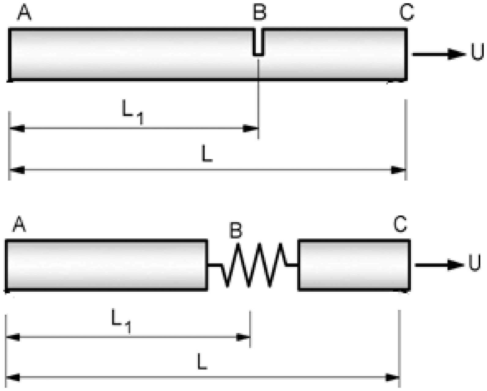
The equation of the motion of Euler-Bernoulli for axial vibration is given by
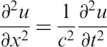
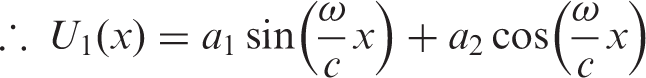
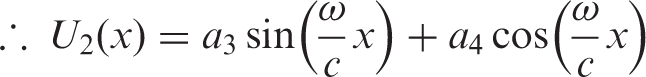
This equation does not hold near the crack, due to abrupt change of the cross section. The beam can be treated as two uniform beams, connected by an axial spring at the crack location. The equation (1) is then valid for each segment of the beam separately, with the appropriate boundary condition. The left segment of the beam will be designated by subscript 1 and the right one by 2. The end points are designated by A and C, and the crack section by B. The beam equation (1) is solved by standard method of separation of variables, hence for two beam segments we get
For the free vibrations of the beam, there is no external excitation and consequently no axial force at the ends.
Also, the continuity conditions at the crack position the displacement, moments, and shear forces are
With the nondimensional crack section flexibility denoted by Θ, the angular displacement between the two beam segments can be related to the force at this section by

Substituting above boundary conditions in equations (2), (3) and equating the system determinant to zero and obtains algebraic equations for the natural frequencies of the cracked beam, where, ΘA is nondimensional axial flexibility = (EI/KxL), β is nondimensional frequency parameter =
The linear set of equation reduces to a single trigonometric equation

The above equation is finding out by solving the matrix by using a computational package MATHCAD. For constant crack location, a partial differentiation with respect to ΘA yields

If it is assumed that the original beam was uncracked, with negligible equivalent flexibility, the nominal values of ΘA in above equation become zero. When ΘA = 0 and β = nπ, we get

This can be written as a difference equation

By definition of the nondimensional frequency parameter, it is given that 2 Δβ/β = Δf/f. Therefore equation (9) can be rewritten for the ith mode as

For the first natural mode β1 = 1π, therefore above equation yields
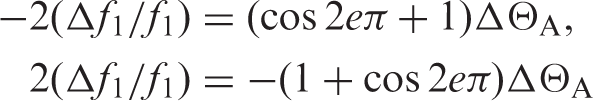
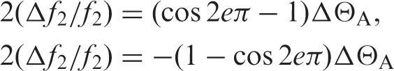
And for the second mode β2 = 2π, therefore, above equation yields,
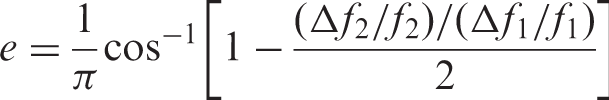
Dividing equation (12) by equation (11) and simplifying we get
Identification of crack size in for free–free beam
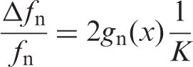
Consider a typical beam structure that has been damaged by a discrete crack. Based on the consideration of the characteristic equations of the physical model shown in Figure 1. The eigenfrequency change ratio Δfn/fn and the dimensionless stiffness K is given as,


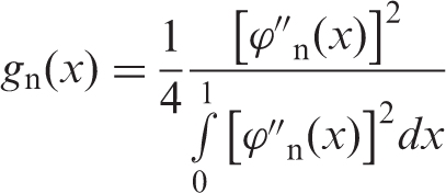
The gn(x) function for a free–free beam can be evaluated as
From elementary beam theory, the mode shapes of beams with typical homogeneous boundary conditions can be easily calculated. For free–free beam, the mode shape is
The spring stiffness Kx in the vicinity of the cracked section of a beam having width b, height h, and crack depth a. From the crack strain energy function, given by Rizos and Aspragathos (1990),
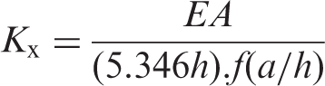
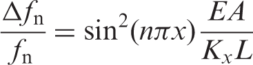
Putting this value in equation (17), we get
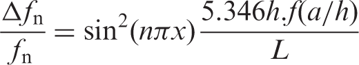
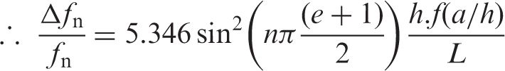

Putting this value in equation (20) and neglecting higher order values, the equation becomes
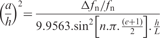
Using equation (21), we can easily find out the crack depth ratio (a/h) if we know the natural frequencies of uncracked and cracked beam and crack location.
Analysis of cracked beam by ANSYS FEM package
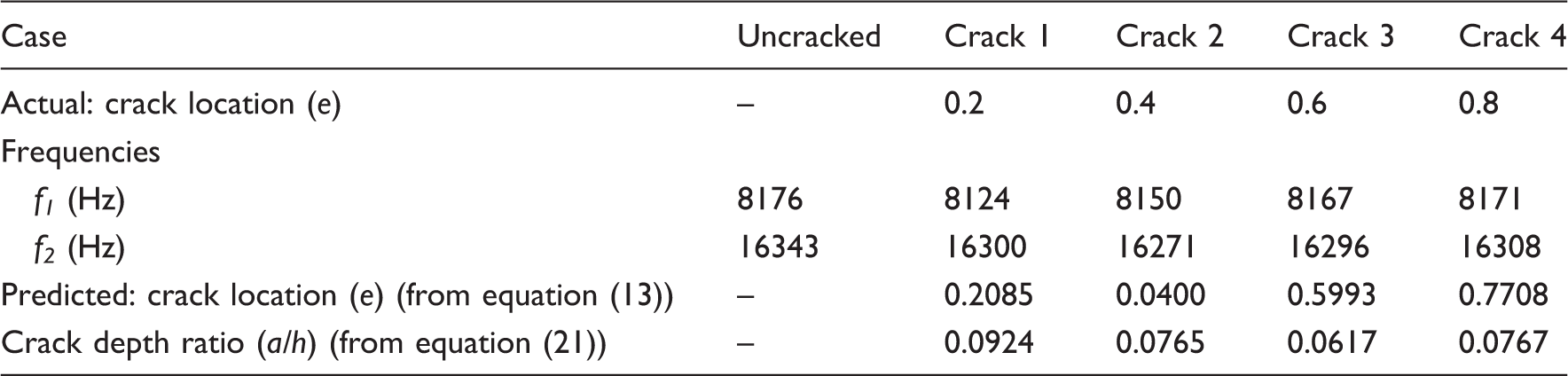
Results of aluminum beam with crack depth ratio (a/h) = 0.1 by ANSYS.
Analysis of cracked beam experimentally
The experiments are done on free–free beam having a crack. The tests are carried out for different crack location and for different crack size. The experimental set up consists of the test instruments shown in Figure 2. The test specimens have length 300 mm and rectangular cross section 10 mm in breadth and 25 mm in depth. Both ends of the beam are wound with two strings and suspended freely with frame. This was attempting to simulate the free–free boundary condition.
Experimental setup of free–free beam.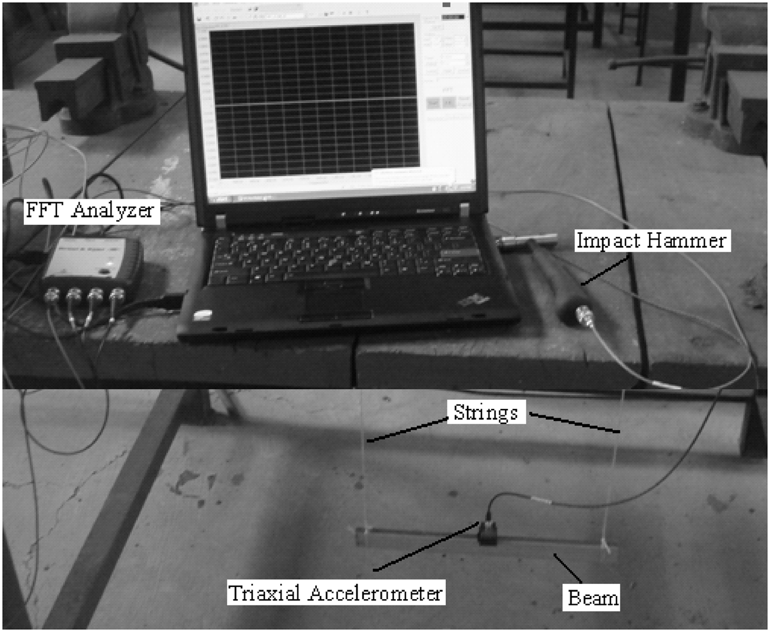
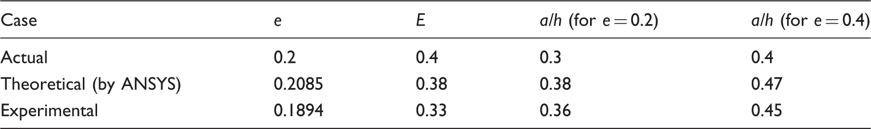
Actual, theoretically, and experimentally predicted crack location (e) and crack size (a/h).
Results
The various results obtained by theoretical (ANSYS) and experimental analysis for identification of crack location and crack size are shown in Figure 3 in the form of graph.
Graph relating the theoretical and experimental crack location (e) to crack size (a/h).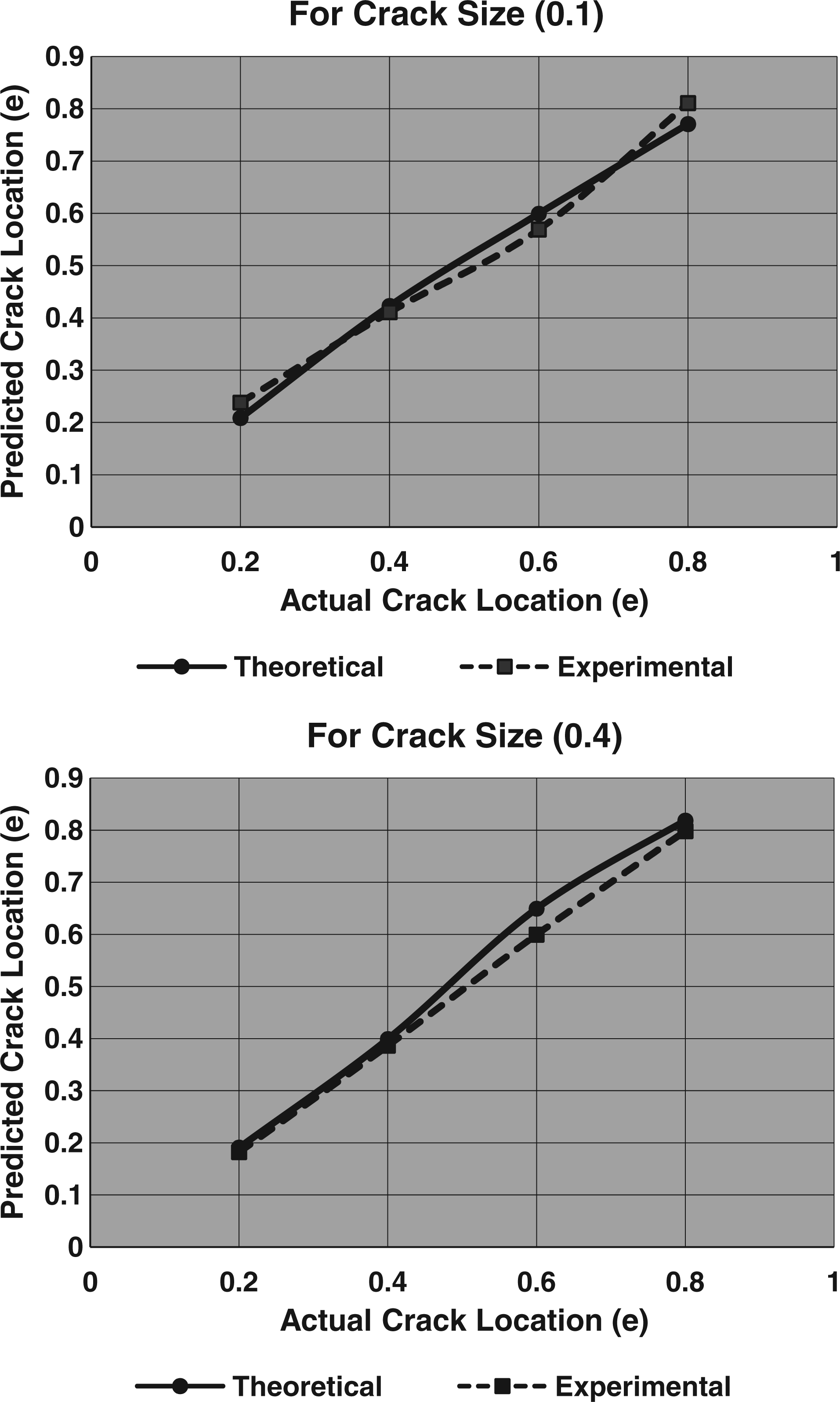
Conclusions
In this paper, a method for detection of crack from measurement of natural frequencies of cracked free–free beam for axial vibration is developed. For identification of crack location and crack depth ratio, it was shown that data on the variation of the first two natural frequencies is sufficient. The crack is simulated by an equivalent axial spring, connecting the two segments of the beam. Analysis of this approximate model results in algebraic equations, which relate the natural frequencies of beam and crack location. These expressions are applied to studying the inverse problem, that is, identification of crack location from frequency measurements. For crack size an integrated approach is used, which gives a relation between frequencies’ changes, crack location, and crack size in the beam. The error in prediction of crack location and crack size by theoretical and experimental analysis is less than 16%. The proposed method is conformed by comparing it with results of ANSYS FEM results. The proposed method is found to be both simple and accurate.