
Abstract
Ultrasonic fatigue tests at the frequency of 20 kHz were carried out on the hot rolled low alloy steel grade (known as R5), which according to the International Classification Society of offshore systems, it is a steel with the highest ultimate tensile strength to manufacture mooring chains and accessories intended to position mooring applications. Tests were carried out at constant load ratio R = −1 on pre-corroded and no-corroded hourglass shape specimens; pre-corrosion was implemented according to ASTM standard G85. Stress concentration between two and three close hemispherical pitting holes on hourglass shape specimen undergoing uniaxial loading were obtained by finite element method. Experimental results show that fatigue life decreases with the proximity of two close pitting holes on the fracture surface. An exponential law is proposed for the stress concentration factor evolution with the proximity of two close pitting holes of identical radius; the trend of this law is confirmed by experimental results. Finally, fracture surfaces were analyzed and conclusions were listed concerning fatigue life, proximity of pitting holes on fracture surface, and the associated stress concentration factors.
Keywords
Introduction
Steels combined with corrosion attack are commonly present in industrial applications: offshore petroleum platforms, combustion camera engines, oil and gas pipelines, bridges, marine and planes structures, vessels containing corrosion fluids or gas, etc. (Abolikhina and Molyar, 2003; Chandler, 1985; Galtier and Bertrand, 2002; Jacobson, 2005; MacClelland and Reifel, 1986; Song and Saraswathy, 2007). Very often in these applications, the mechanical elements are subjected to oscillating loads and environment leading to fatigue-corrosion conditions. Then, it is of principal interest for fatigue prevision design to investigate the relationship between fatigue life and the stresses concentration induced by corrosion pitting holes (Loganathan et al., 2010; Shi and Mahadevan, 2001; Wang et al., 2003).
It is known that corrosion reduces dramatically the fatigue life of mechanical elements (Dolley et al., 2000; DuQuesnay et al., 2003; Shi and Mahadevan, 2003) even though, little studies have been destined to assess the effect of pitting holes proximity on fatigue life. Geometrical and space properties of pitting holes during the corrosion process such as: shape, dimensions, distribution, and proximity are critical parameters inducing an increase on stress concentration factors (SCFs); nevertheless, the influence of these parameters on fatigue life has not been deeply analyzed at the present (Dominguez Almaraz et al., 2010; Medved et al., 2004; Rokhlin et al., 1999).
In this study, the effects of pitting holes proximity and the associated SCFs on the ultrasonic fatigue life have been studied for a low alloy steel. Numerical investigations have been carried out in order to assess the stress concentrations factors for one, two, or three pitting holes under uniaxial loading.
Displacement and stress along the ultrasonic hourglass shape specimen
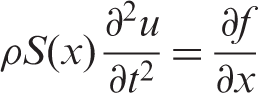
Ultrasonic fatigue tests were carried out on the hourglass shape specimen under resonance condition: longitudinal natural frequency of specimen close to the external excitation frequency of 20 kHz. Figure 1 shows the geometrical parameters of the hourglass shape specimen used for experimental testing; the curve section is defined by a hyperbolic function (Green, 1991; Salama and Lamerand, 1982). The longitudinal wave equation for a non-constant specimen section is
Geometrical parameters for ultrasonic fatigue specimen.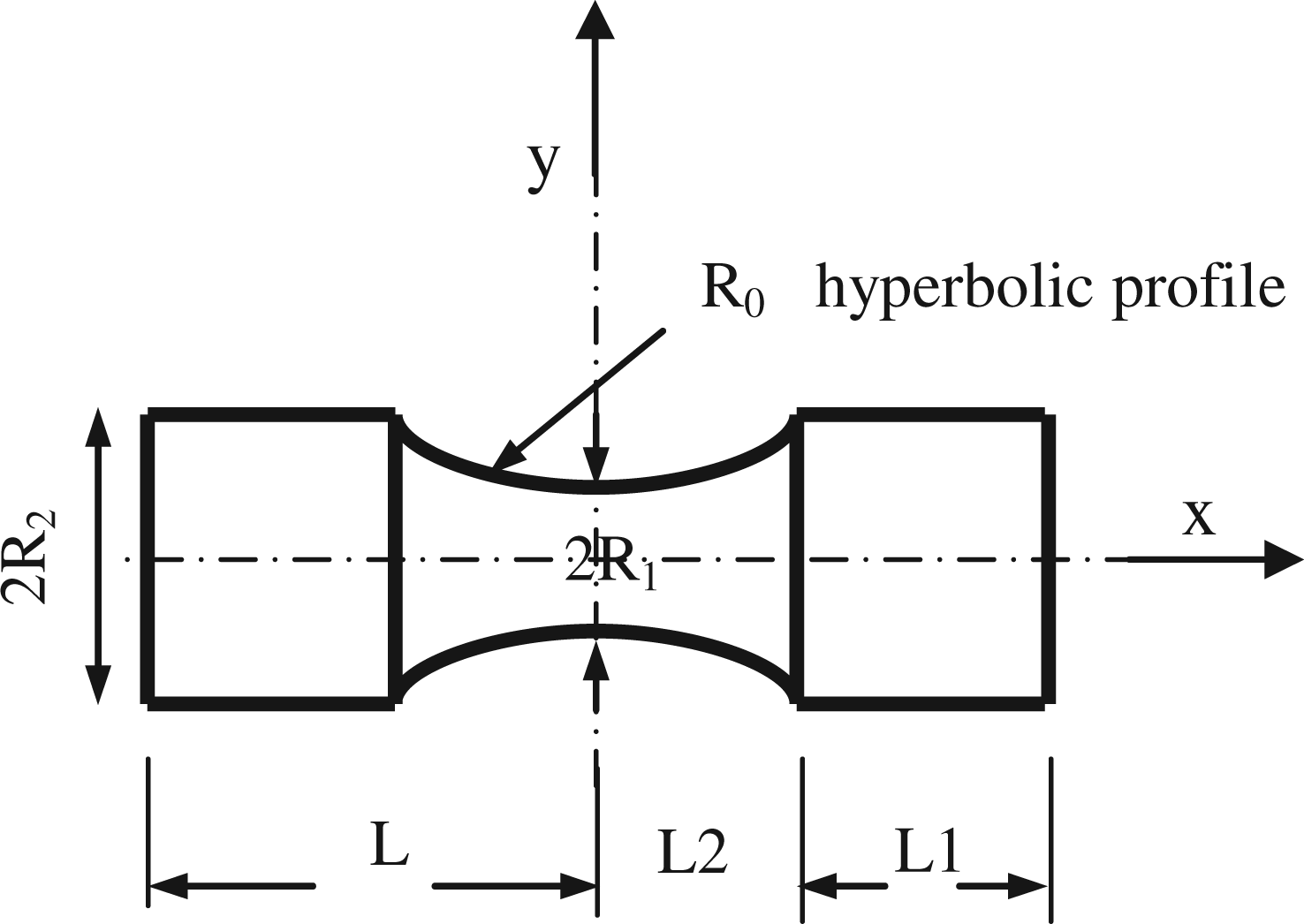
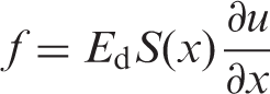
Here, Ed is the dynamic elastic modulus. In substituting equation (2) into equation (1) that yields
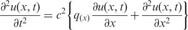
With c representing the longitudinal propagation speed in the specimen:
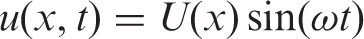
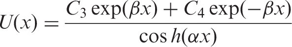
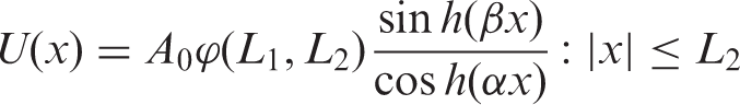
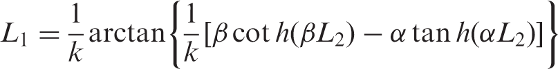
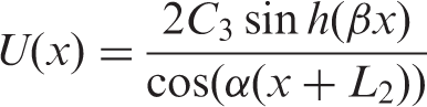
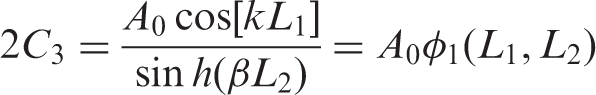
Here, U(x) is the longitudinal displacement in each point of specimen, following the x-axis. Substituting in equation (3), the differential equation is

The second derivative in time has been converted to spatial function U(x) with:


With the associated relations: α = (1/L2) cosh−1(R2/R1) and L = L1 + L2. The surface function S(x) is defined in each section by the expressions
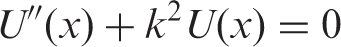
For the specimen constant section (equation (6a)) it is found S′(x) = 0, and q(x) = 0, the differential equation is reduced to
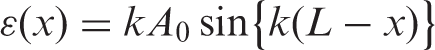
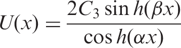
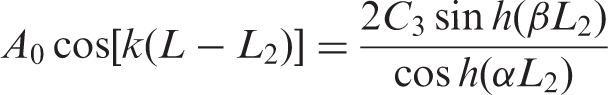
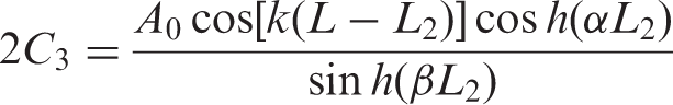
For the non-constant section, equation (6b), For the non-constant section (equation (6b)), two intervals are proposed for the sinusoidal function
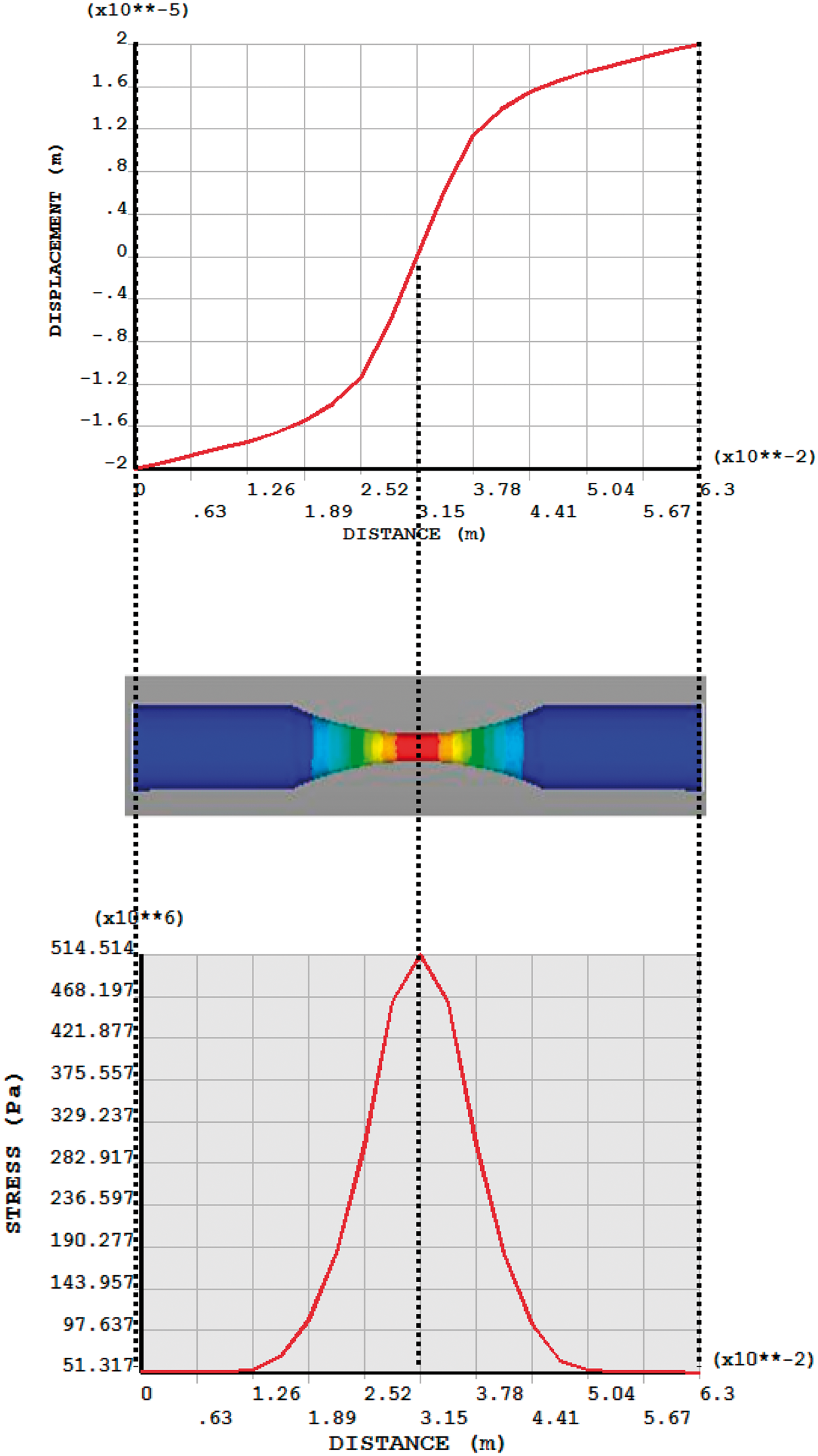
Displacement and stress along the hourglass shape specimen used in ultrasonic fatigue tests.


Numerical results for stress concentration in hemispherical corrosion pitting holes
Figure 3 shows the principal stress distribution under uniaxial loading on the hourglass shape specimen’s surface and for the cases: without pitting and with one, two, and three hemispherical pitting holes localized at the specimen narrow section (narrow section diameter = 3 mm). All hemispherical pitting holes in these numerical simulations present a diameter of 200 µm. The principal stress distribution for the non-corroded specimen is shown in Figure 3(a); the high stress is close to 425 MPa when a tension displacement close to 19 µm in opposite direction is applied at two extremes of specimen. Concerning specimens with hemispherical pitting holes, numerical simulations show that for one pitting hole and identical loading condition (Figure 3(b)), the high principal stress was close to 950 MPa, implying a SCF Kt ≈ 2.24; this last value exceeding the reference SCF Kt ≈ 2.09 for a hemispherical pitting hole under uniaxial loading and in a flat surface (Paris et al., 2009). Variation on Kt should be the effect of the curve surface of specimen; particularly, the ratio between the diameter of pitting hole and the specimen diameter at narrow section (Pilkey and Pilkey, 2007): if this ratio approaches zero, the condition of flat surface is reached. For two pitting holes separated 50 µm and with the horizontal diameters lying in a perpendicular plane regarding the applying uniaxial loading (Figure 3(c)), the high principal stress is close to 1040 MPa; the SCF results in an exponential function of the two pitting holes separation (Dominguez Almaraz et al., 2010). Finally, three pitting holes arranged, as shown in Figure 3(d), induce a high principal stress under identical loading conditions of 955 MPa, similar to one pitting hole case.
Principal stress distribution (Pa) for specimens without pitting (a), one pitting (b), two pitting (c), and three pitting (d), 19 µm of tension displacement at the two extremes of specimen and all pitting holes with 200 µm of diameter.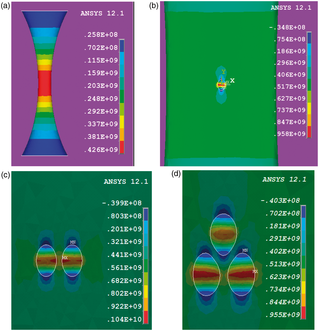
Experimental details
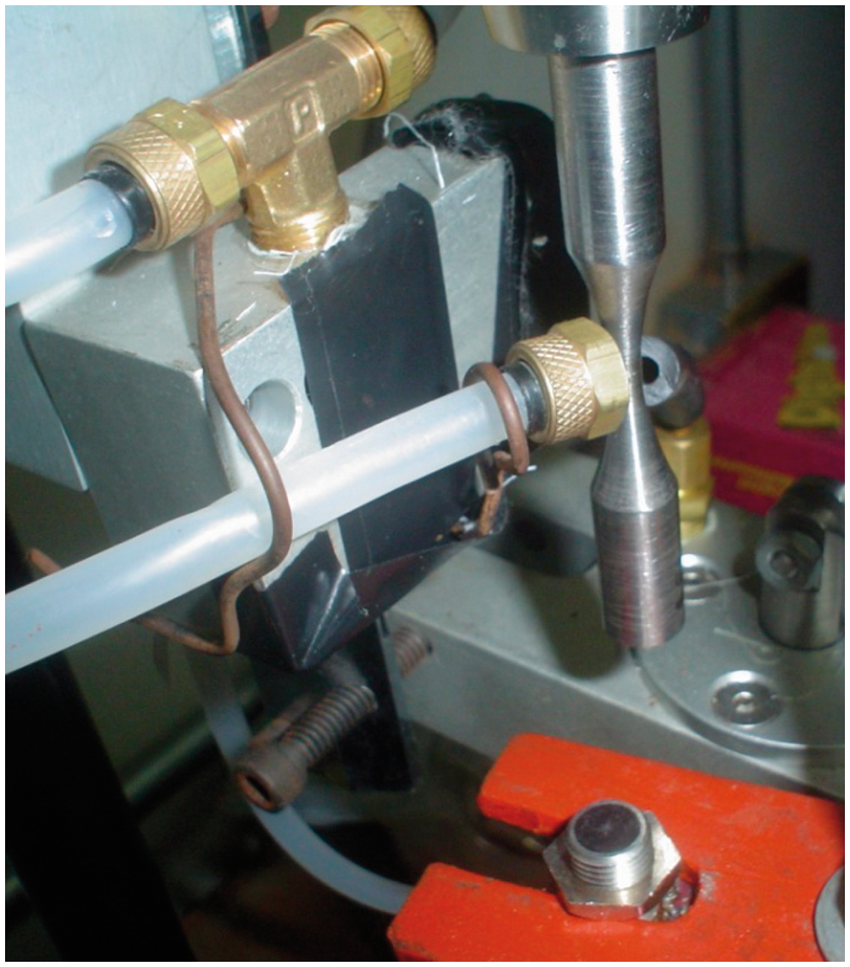
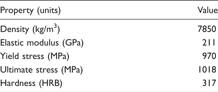
The material used in this study is a non-standard hot rolled low alloy steel grade (known as R5) with a typical fine grain microstructure, composed by tempered martensite and bainite (Figure 4). This steel is commercialized after a double quenching in water at 920℃, then 880℃ and tempering at 650℃ with water cooling. The chemical composition and principal mechanical properties are presented in Tables 1 and 2, respectively. Tests were carried out in an hourglass shape specimen with geometrical dimensions calculated by finite element method (FEM) in order to fit the resonance condition under ultrasonic fatigue testing (Marines et al., 2003). All specimens were tested at room temperature without control of the environmental humidity and temperature at specimen narrow section was controlled by cooling system with pressured cool air (Figure 5). The surface roughness number parameter was Ra = 0.8 µm, for the non-corroded specimens after machining and constant load ratio R = −1 was applied on pre-corroded and non-corroded specimens at the ultrasonic frequency of 20 kHz. Displacements at the extreme of specimen were calibrated by an inductive sensor (Figure 5) with linear displacement ranging from 0.5 to 5 mm and resolution <0.08% of full scale output (±3 µm)·
R5 steel microstructure after heat treating and nital etching (a), non-metallic inclusions in dark (b). Ultrasonic setup: specimen, cooling system, and inductive sensor for displacement calibration. Chemical composition. Principal mechanical properties.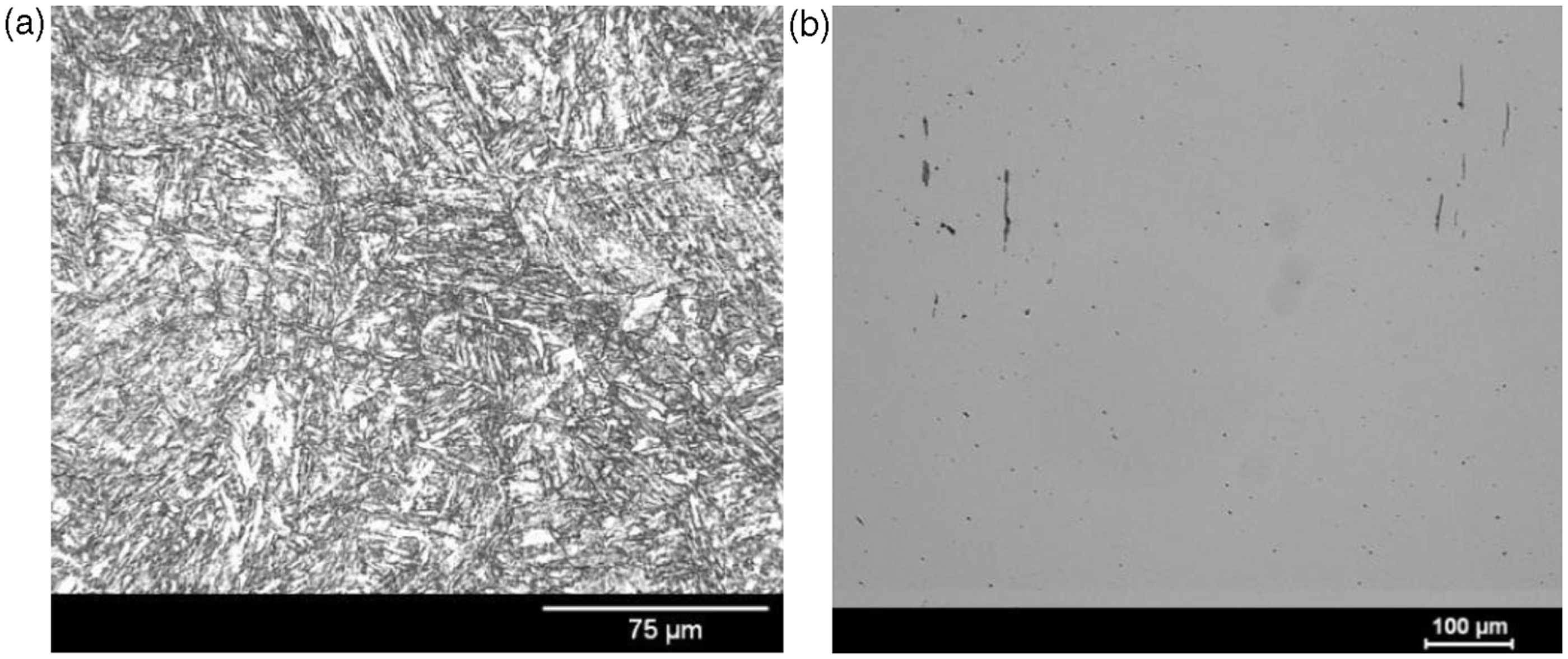

Pre-corrosion of specimens
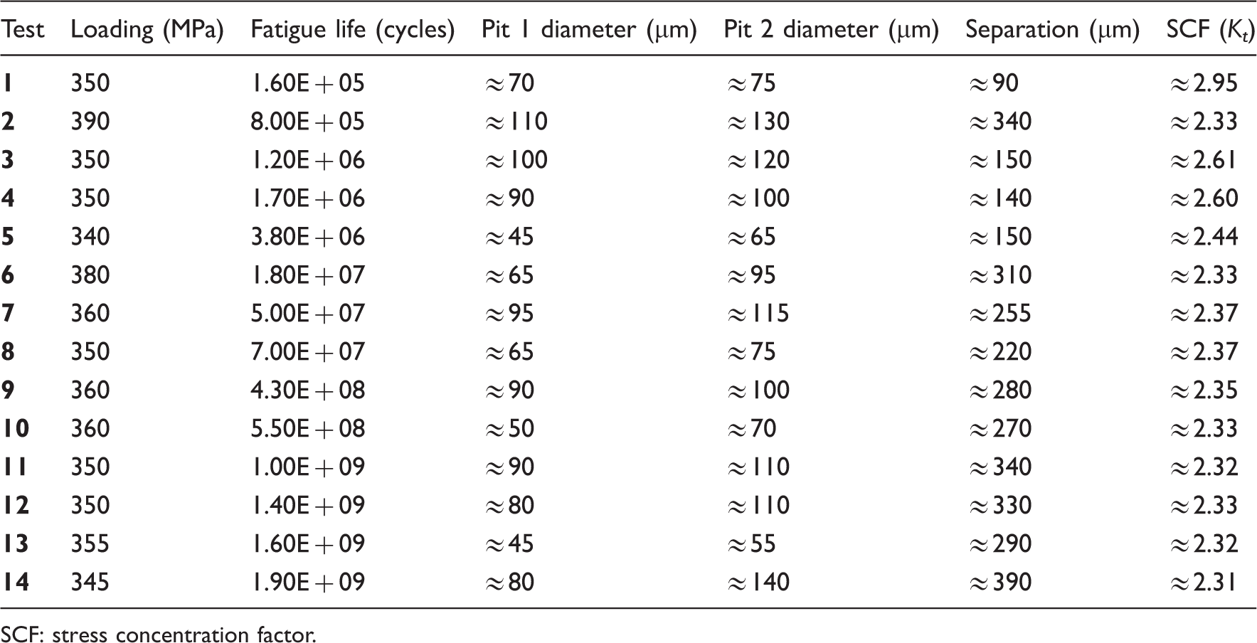
Pre-corroded specimens have been obtained by the ASTM standard G85: Standard Practice for Modified Salt Spray (Fog) Testing, consisting on the specimen’s stay of 600 h in a salt fog corrosion chamber under temperature and humidity control: 35℃ and 95% of humidity. The salt solution concentration of NaCl was 5%, with a pH of 6.6 and it is applied to the corrosion chamber with a rate flow of 1.5 mL/h. After the pre-corrosion process, all specimens are cleaned by a chemical solution in a first step and then with emery paper to remove the oxide layer. Pitting corrosion is induced on the specimen surface after the pre-corrosion process; the observed pitting holes diameter varies from 45 to 140 µm and separation between the two crack initiation pitting holes ranges from 90 to 390 µm (Figure 6 and Table 3).
Crack initiation pitting corrosion holes at fracture surface: localization, dimensions, and separation. Fatigue life, geometrical properties of two crack initiation pitting holes at fracture surface, and SCF calculated by equation (1). SCF: stress concentration factor.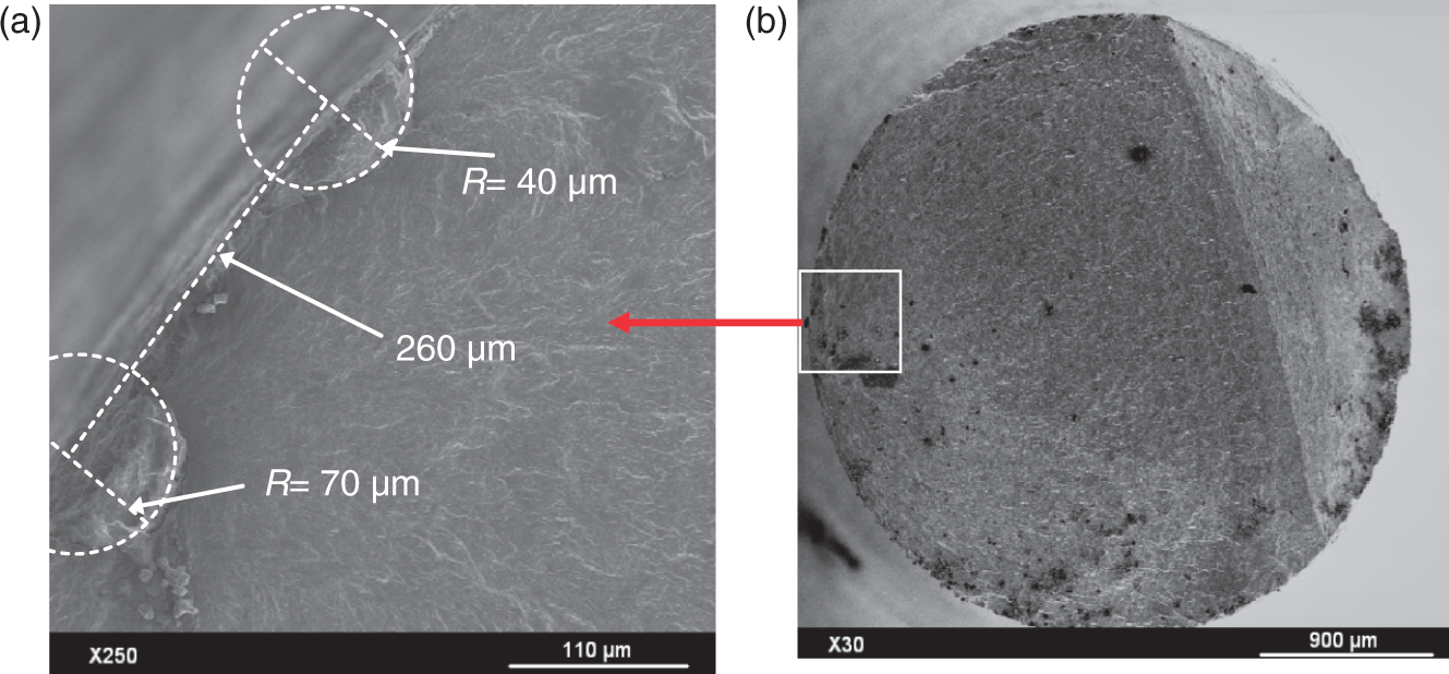
Results
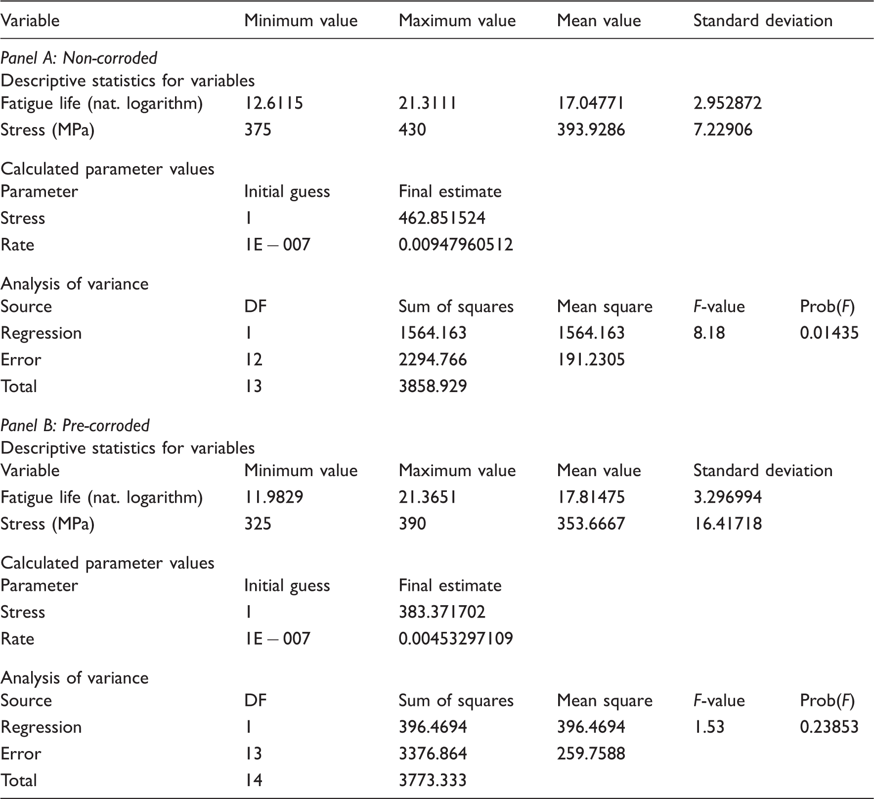
Ultrasonic fatigue results on pre-corroded and non-corroded specimens are plotted in Figure 7. Fatigue endurance is reduced about 45 MPa from the non-corroded to pre-corroded specimens, as it is observed in this figure in comparing the two corresponding non-linear regression lines (Bates and Watts, 2008; Koeppe and Hamann, 1980; Table 4). Experimental results on the pre-corroded specimens present high scattering that should be related to pre-corrosion process; an analysis on specimens’ fracture surface allows observing some relationship between the proximity of crack initiation pitting holes at fracture surface and fatigue life. The effects of crack size and the separation between the two crack initiation pitting holes have been correlated to fatigue life in the case of pre-corroded specimens in order to prove its influence in modifying the scattering experimental points in Figure 7. The results of this correlation are shown in the last figure with the points in yellow. It was proposed an equivalent loading σeq in function of the average pitting radius r (µm), the separation S (µm) between the two crack initiation pitting holes and the nominal loading σn (MPa) listed in Table 3
Ultrasonic fatigue results on non-corroded specimens and on pre-corroded specimens: experimental points and points plotted with the ‘equivalent stress’ σeq. Statistic parameters for non-linear regression on specimens.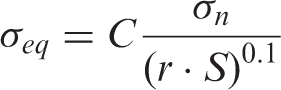
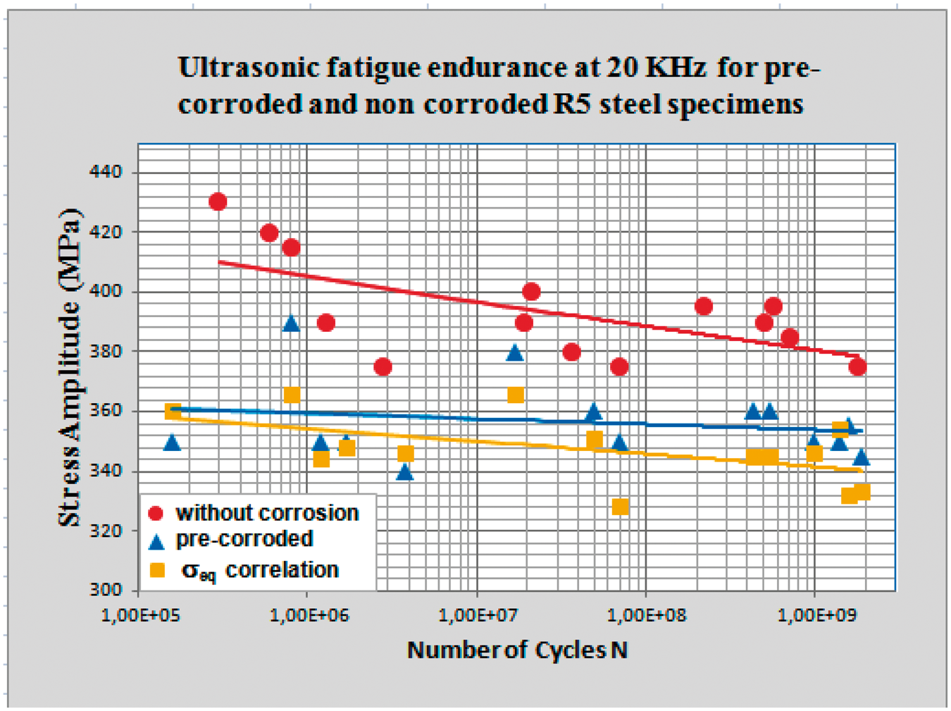
Taking two results for pre-corroded specimens plotted in Figure 8: 340 MPa, 3.8 × 10⁶ cycles for the first one and 380 MPa, 1.8 × 10⁷ cycles for the second. The fracture surface for the short fatigue life pre-corroded specimen is shown in Figure 8(a) and (b): two hemispherical pitting holes are observed at the specimen surface with diameters of 45 and 65 µm, separated a distance of 150 µm. The presence of hemispherical holes on the specimen surface enduring tension-compression load induces stress concentration often surpassing the nominal stress σn (Cerit et al., 2009; Dominguez Almaraz, 2008). In the case of high fatigue life pre-corroded specimen (Figure 8(c)), the fracture surface shows again two pitting holes: 65 and 95 µm, but this time they are separated by 310 µm. The second specimen shows high fatigue life with a factor close to 5 in regard to first one, even if the loading is higher of 40 MPa. In Table 3 are listed the results for the pre-corroded specimens with the corresponding diameters and separation of the two crack initiation pitting holes at fracture surface, together with the calculated SCF.
Two pitting holes located at the fracture surface, (a) and (b) 340 MPa, 3.8 × 10⁶ cycles and (c) 380 MPa, 1.8 × 10⁷ cycles.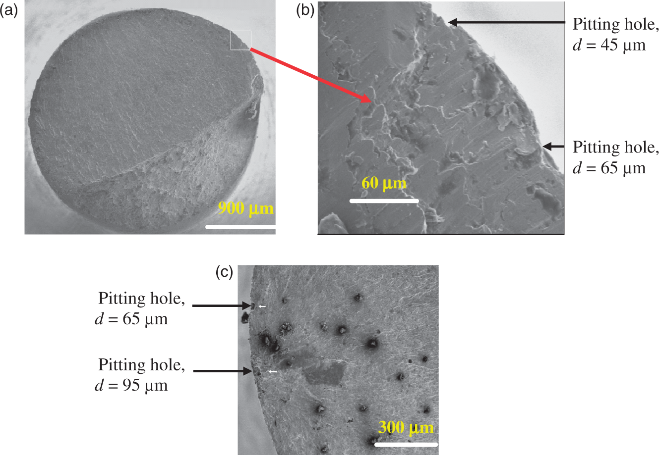
Discussion
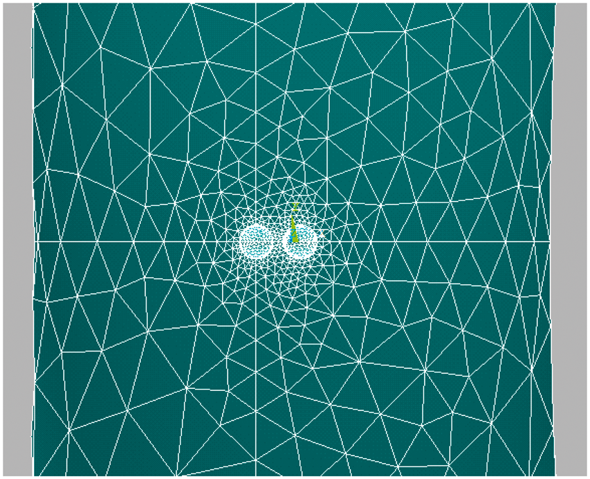
Numerical stresses concentration factors increase with the proximity of two close pitting holes; these values were obtained for the hourglass shape specimen under uniaxial loading. Finite element selected for FEM simulation was the three-dimensional (3D) ‘solid 185’ in ANSYS software; it is defined by eight nodes having three degrees of freedom at each node: translations in the nodal x-, y-, and z-directions. Automatic meshing was used to the model; nevertheless, element size at the critical zones (stresses concentration zones) was as fine as necessary to capture the real stress distribution (Figure 9). An exponential relationship between the SCF and the proximity of the two crack initiation pitting holes under uniaxial loading is proposed; this is a modified exponential law regarding the last one proposed (Dominguez Almaraz et al., 2010)
Two close pitting holes and automatic meshing for numerical simulation.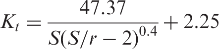
Here, Kt is the SCF, S the separation in micrometers between the pitting holes centers, and r the identical radius in micrometers for the two hemispherical pitting holes. Stress concentration Kt increases when the two hemispherical pitting holes approach: Kt ≈ 2.5 for r ≈ 100 µm and S ≈ 250 µm; whereas weak interaction between the holes is expected for r ≈ 30 µm and S ≈ 400 µm; this last condition approaching the SCF for one single pitting hole on the hourglass shape specimen (Kt ≈ 2.25). The exponential law expressed by equation (36) contributes to assess the experimental results of pre-corroded specimens plotted in Figure 7: short fatigue life for similar loading conditions is related to high SCF, as it is observed from the fatigue tests number 1, 3, 4, and 5 in Table 3. The values of Kt in Table 3 have been evaluated taking the average radius of the two concerned pitting holes.
The observed reduction on strength presented in Table 3 is generally less than the obtained Kt values; this is associated with the size and notch radius of the corrosion pitting holes: these ones are small enough to limit the crack propagation related to fatigue strength reduction less than Kt. Furthermore, notch sensitivity factor q is expressed by
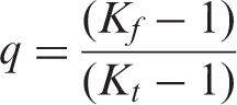
Comparing theoretical SCF Kt, to the fatigue notch factor Kf. Notch sensitivity factor q significantly decreases with smaller notch radii; although it seems not evident, it occurs because Kf increases more slowly than Kt with decreasing notch radius.
Exponential evolution of Kt related to two close hemispherical pitting holes under uniaxial loading is plotted in Figure 10, for two sizes of the pitting radius r = 33 µm and r = 100 µm: Kt increases when S/r ratio decreases and this behavior is enhanced for low average pitting hole radius.
SCF (Kt) variation with the ratio S/r, under uniaxial loading.
No interaction between the dynamic corrosion process and the mechanical loading on pre-corroded specimens has been developed during testing: pre-corrosion is applied before the mechanical loading and the relationship between the 3D growth behavior of pit and local stress and strain distributions around pit under cyclic stress condition (Maa et al., 2010) is not reported in this study. Nevertheless, the pre-corrosion process induces pitting distribution on the specimen surface with pit parameters such as: diameter, depth, distribution, and size influencing the fatigue endurance of this steel. Separation and size of two crack initiation pitting holes are the parameters analyzed in regard to ultrasonic fatigue endurance and SCFs of the studied material.
Figure 3(d) shows the result of simulation for the principal stress distribution in the case of three close pitting holes; the high stress is close to high principal stress for the one single pitting hole (Figure 3(b)). The three pitting holes seem to represent a large single pitting hole with circumference comprising the three pitting. The last assumption implies that no dimension effect is expected for the high principal stress value of a single pitting hole, under described loading conditions. Recent numerical investigations (Cerit et al., 2009) have shown that the evolution of SCFs under uniaxial loading on a single pitting hole is a function of depth, size, and shape of the pit; then, further investigations are required for the understanding of SCF variation with the geometrical properties of the pit and the variation with such properties interacting with the proximity of two close pitting holes.
Conclusions
The following conclusions are related to this study:
Fatigue endurance decrease dramatically on metallic alloys with pitting holes, compared to same material without pitting. The high stress in one pitting hole undergoing uniaxial stress is located at the bottom of the hole; the localization changes to the common wall of two pitting holes when they approach. The proximity of two close pitting holes at fracture surface was associated with the fatigue life reduction in this study. For real material with pitting holes (cast iron, corroded, or pitting elements), the probability to find two or more close pitting holes is high; then, SCFs should be estimated under this condition. Experimental points scattering on pre-corroded specimens is reduced when points are plotted using the correlated equivalent loading σeq. An exponential law is proposed in this article relating SCFs with the pit radius r and the separation between the two pits S. Further investigations should be necessary on this direction; particularly, the relationship between the SCF and the localization, geometry, and dimension of two or more close pitting holes produced by corrosion, the effect of loading ratio R on these concerns and, in general, the fatigue endurance behavior related to these mechanical and corrosion factors.
Footnotes
Acknowledgments
The authors express their gratitude to the University of Michoacan and the Advanced Technology Center of Queretaro in Mexico, for the facilities received in preparing this study. A special mention of gratitude to CONACYT (The National Counsel for Science and Technology in Mexico) for the financial support destined to this study.
Funding
This research work has received grants from the CONACYT (The National Counsel for Science and Technology in Mexico), through the project: CB No. 82403.