
Abstract
This paper reports the low-cyclic tensile responses of three-dimensional orthogonal woven composites based on the micro/meso-scale repetitive unit cells with elastic/viscoelastic models. The repetitive unit cell models for the resin impregnated fiber tows and the three-dimensional orthogonal woven composites at the fabric microstructure level were established. In the micro/meso-repetitive unit cells model, a nonlinear viscoelastic relationship with switch rule is introduced to characterize the mechanical behavior of the resin for the loading/unloading conditions. The fiber/fiber tows are characterized with linear elastic models. And damage initiation and postdamage constitutive models are also included for matrix/fiber and matrix impregnated fiber tows in the finite element analysis. The fatigue model with the mechanical parameters transferred from micro-scale to meso-scale model is numerically simulated with user-defined material subroutine and incorporated into commercial finite element software ABAQUS/Standard. The calculated results manifest the multiscale fatigue behaviors of three-dimensional orthogonal woven composites, such as the global stiffness degradation, decrease of peak stress, and even local damage behavior. The fatigue behaviors are also verified with the data in experimental and indicated that the model is an efficient strategy to predict the low-cyclic fatigue behaviors of polymer matrix composites.
Keywords
Introduction
The fabric architectures of three-dimensional (3D) orthogonal woven composites (3DOWCs) consist of in-plane layers of warp (0°) and weft (90°) fiber tows interlocked with Z-yarns along thickness direction (Bilisik, 2010; Chen et al., 2011; Jia et al., 2012, 2013a, 2013b). Such geometrical features lead to higher inter-laminar shear strength and impact damage tolerance compared with other textile structural composite materials. 3DOWCs have been regarded as an attractive structural material for multidirectional loadings because of high stiffness, strength, fracture toughness, and damage resistance along transverse direction (Ansar et al., 2011).
Their quasi-static behaviors and damage mechanism are reported a lot in the last two decades based on experimental tests of tensile strength and failure mechanisms (Callus et al., 1999; Chen and Zanini, 1997; Chou et al., 1992; Lee et al., 2002; Quinn et al., 2008; Rudov-Clark and Mouritz, 2008; Rudov-Clark et al., 2003; Tong et al., 2002), compressive characteristics (Baucom and Zikry, 2003; Endruweit and Long, 2010; Kuo et al., 2006, 2007) and shear responses (Chen and Zanini, 1997; Ogasawara et al., 2005), and numerical/analytical models using representative volume element (RVE) (Kim et al., 2008; Lee et al., 2005) or repeating unit cells (RUCs) (Belarbi et al., 2012; Bogdanovich, 2006, 2008; Chou, 1995; Kuo, 2008; Li et al., 2011; Tan et al., 1998, 1999, 2000, 2001), micromechanical strength model (Karkkainen and Tzeng, 2009). For the cyclic loadings, the fatigue properties of 3DOWCs are analyzed mostly by means of experimental methods, such as compressive–compressive (Dadkhah et al., 1995), tensile–tensile (Ding et al., 1995; Mouritz, 2008; Rudov-Clark and Mouritz, 2008) and tensile–compressive tests (Marcin et al., 2011). The above-mentioned RVE/RUCs include direct numerical simulation, laminate block, mosaic models, and micromechanical strength model. However, the details of local stress distributions at fiber or fiber tow scales have been neglected. Furthermore, the “plane-remains-plane” boundary conditions, with overconstrained boundary conditions under shear loadings as indicated in Sun and Vaidya (1996), were applied in these models.
Here we investigate the global and local characteristics of low-cycle fatigue of 3DOWCs using micro/meso-scale RUCs with low-cycle fatigue model as an extension of previous researches (Jia et al., 2012, 2013a, 2013b). For the periodic array of 3DOWCs in-plane principal directions, the micro/meso-RUCs were established with application of periodic boundary conditions (PBCs) as stated in our previous work (Jia et al., 2012). In the multiscale analysis under cyclic loading, the matrix was represented by nonlinear viscoelastic constitutive model with damage occurrence and switch rule for loading/unloading cases. The fiber and resin impregnated fiber tows are characterized by linear elastic models with damage initiation and evolution. This fatigue model by multiscale microstructure approach was implemented with user-defined material subroutine (UMAT) and incorporated into commercial finite element software ABAQUS/Standard. Multiscale fatigue behaviors of 3DOWCs are predicted in terms of the local crack damage, cyclic responses, and global progressive stiffness degradation. They have been compared with experimental in good agreement.
Fatigue test
The 3DOWC was manufactured in Figure 2 in previous work (Jia et al., 2012). The efficient sizes of a dog-bone shape sample in the middle region are 60 mm (in length), 9.6 mm (in thickness), and 13 mm (in width), respectively, being fabricated with the weft yarn and warp yarn layers (with linear density of 800 tex, E-glass fiber) interlaced with Z-yarns (with linear density of 56 tex, E-glass fiber) along thickness direction. The specimen (with fiber volume fraction of 43.7%) consisted of 17 layers of weft yarns and 16 layers of warp yarns with weaving densities of 50 and 47 ends in weft and warp direction, respectively.
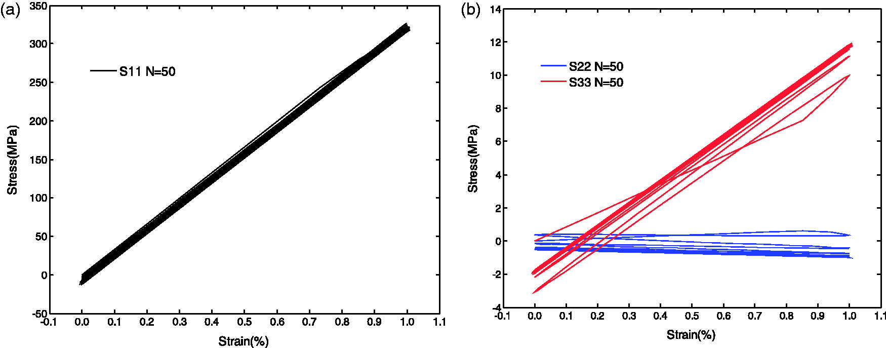
The experimental tests were performed on MTS-810 machine, with a strain gauge in the middle of the coupon to measure the longitudinal strain responses. Two different loading paths were conducted under the strain control ( Low-cycle tensile behavior of 3DOWCs in case of Low-cycle tensile behavior of 3DOWCs in case of 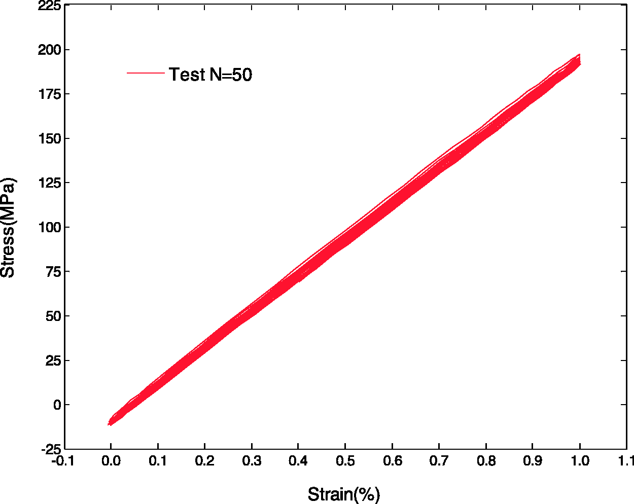
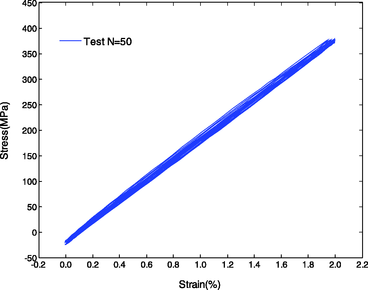
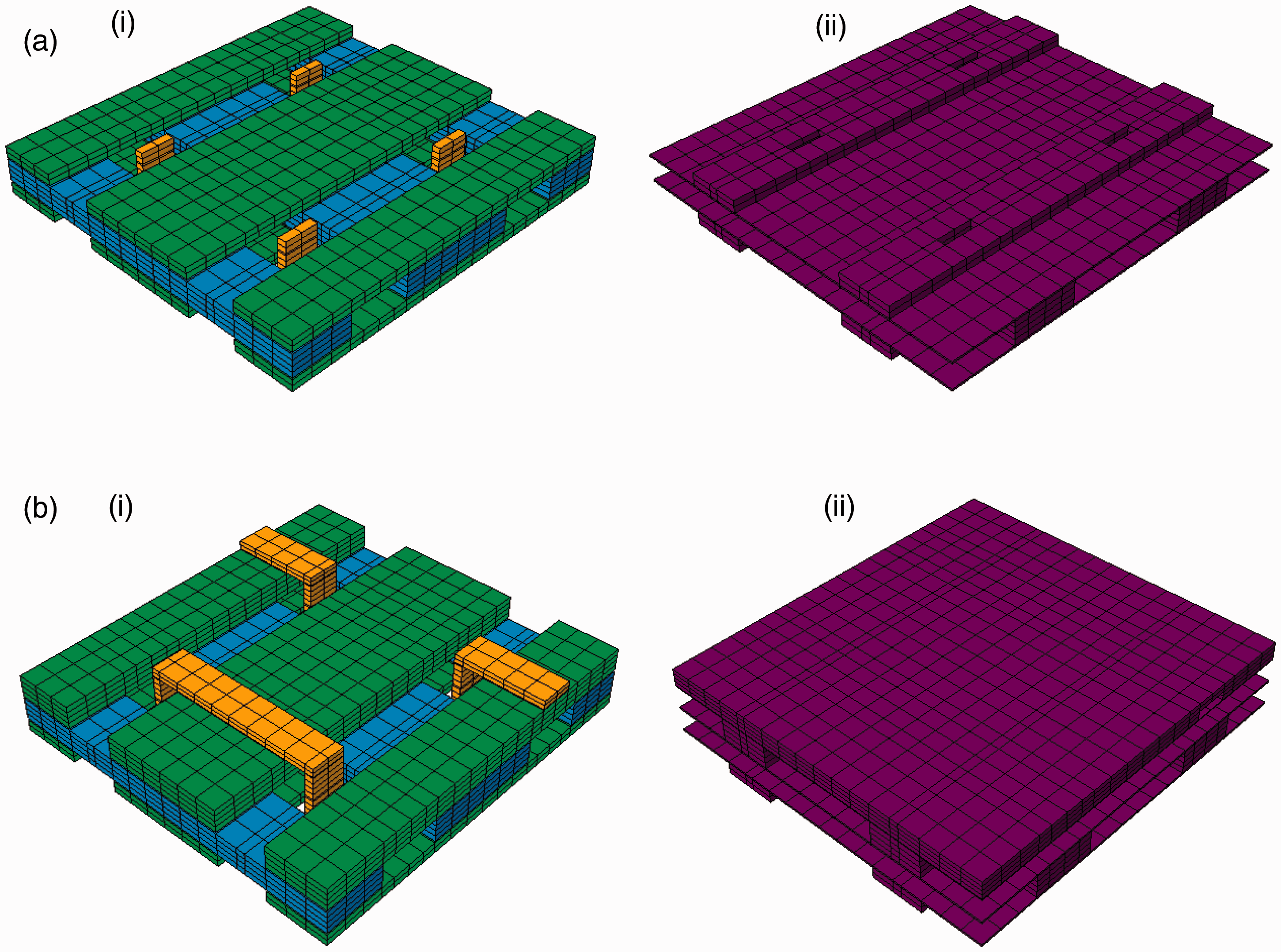
Figure 3 reveals the damage locations in 3DOWC after 500-cycle load in case of Damaged zone distribution in 3DOWC after 500 loading cycles (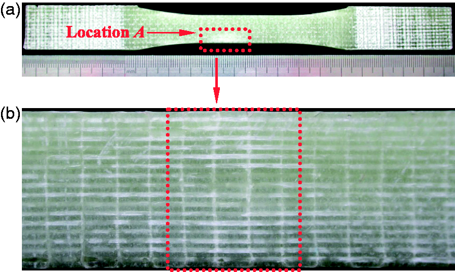
Multiscale geometric models
Meso-RUC model for 3DOWCs
The dimensions of the meso-RUCs for the 3DOWCs were determined in Figure 4(b) based on the linear density of fiber tows and architecture of 3DOWF (Jia et al., 2012, 2013a). In the 3DOWC, the weft-, warp-, and Z-yarns are perpendicular to each other in straight lines and all the yarns have an approximate rectangular cross-section. To reveal the discrepancy of surface area and interior zone of 3DOWC, the sub-meso-scale RUCs were shown in Figure 5. The full thickness meso-RUC of the 3DOWC shown in Figure 4(b) was assembled with repeated inner layers in the middle part and two surface layers on the top and bottom. To reveal the internal architecture of sub-meso-RUCs, the resin and fiber bundles are displayed separately in Figure 5. The differences of the surface and inner layers could lead the different stress/strain distribution under low-cycle tensile loading.
Multiscale FEA model of 3DOWC. (a) Micro-scale level, (b) Meso-scale level. Sub-meso-RUCs for 3DOWC. (a) Inner meso-RUC: (i) inner RUC of 3DOWF, (ii) matrix of inner meso-RUC. (b) Surface meso-RUC: (i) surface RUC of 3DOWF, (ii) matrix of surface meso-RUC.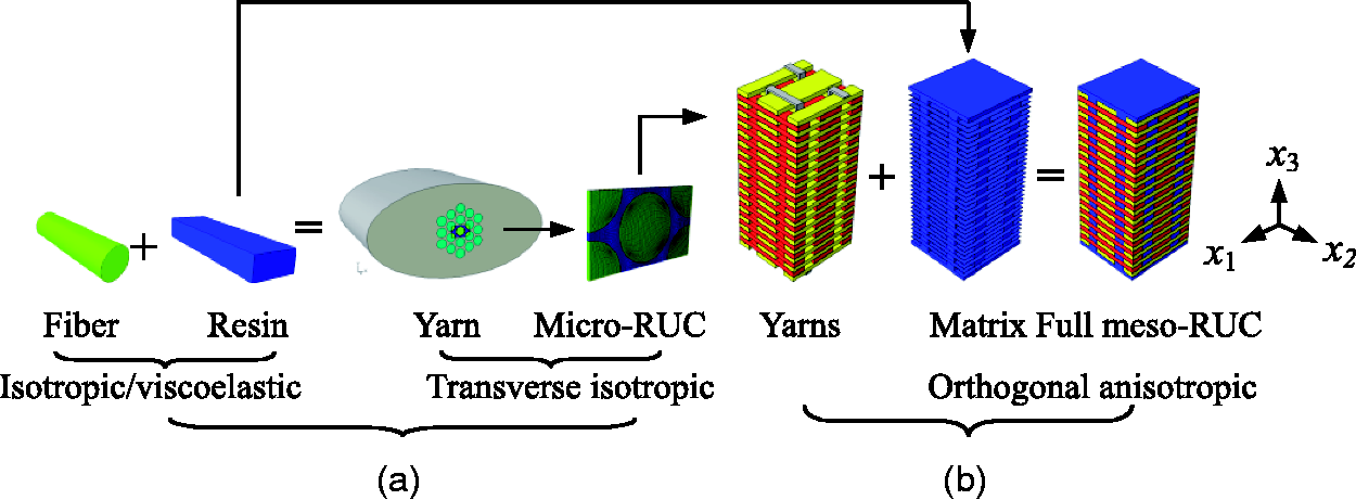
Micro-RUC model for fiber tows
Fibers in the 3DOWCs exist in the form of fibers impregnated with matrix which can be treated as unidirectional fiber reinforced composite. In the micro-RUC analysis of fiber packing patterns in matrix, rectangular cross-section model (Haj-Ali and Muliana, 2004; Xia et al., 2003), column model (Ivanov and Tabiei, 2001) and hexagonal model (Wang et al., 2007) have been investigated. Among them, the hexagonal model was widely applied for modeling transversely isotropic behaviors of fiber tows. In the current study, a rectangular micro-RUC model was determined (Jia et al., 2012).
Fatigue models
Nonlinear/linear constitutive models
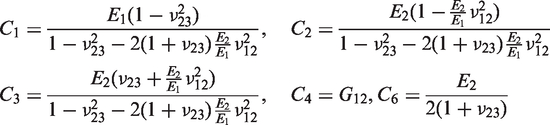
In the multiscale RUCs, the thermosetting polyester resin of AROPO™ INF80501, like other thermosetting resin, behaves like a highly nonlinear viscoelastic response. For accurate predictions of 3DOWC, including fiber and matrix in the form of matrix impregnated fiber tows (micro-RUC) and pure matrix around them (meso-RUC), an accurate constitutive equation to describe the behaviors of matrix material should be introduced to analyze the properties of 3DOWC (Jia et al., 2013a).
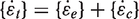
For uniaxial loading, the nonlinear viscoelastic behavior can be expressed by a list of nonlinear “Kelvin-Voigt type” elements and a linear spring element to be connected as shown in Figure 6. For the serial elements, the global stress–strain relation is described with
A nonlinear viscoelastic model with a few Kelvin–Voigt type elements and an elastic spring.
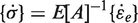
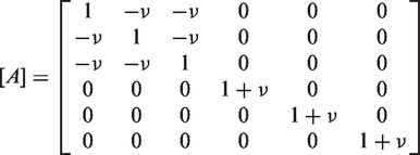
The creep strain rate
In this way all
The nonlinear viscoelastic response in the current model is realized with Ei described by the functions of current equivalent stress,
In the above
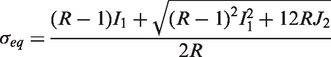
Mechanical properties of AROPOL™ INF80501 polyester and E-glass fiber.
Similarly, the E-glass fiber will be considered as elastic model and micro-RUC will be represented by transversely isotropic material model.
Once the failure criteria are satisfied in the loading procedure, the crack will be initiated as a postdamaged constitutive model on the concept of smear crack.
Damage and postdamage constitutive models
The micro-RUs contain only fiber and matrix and their properties are given in Table 1. For the matrix, a maximum principal strain failure criterion is adopted while a maximum principal stress failure criterion is adopted for the fiber. The meso-RUCs contain fiber tows and pure matrix. For the fiber tows, the failure will initiate if the normal stress in either longitudinal or transverse directions reaches the ultimate longitudinal or transverse ultimate strength. The latter ultimate strength values of the fiber tows are obtained from the FEM analysis on the micro-RUC. And those ultimate strengths will serve as the failure criteria for the corresponding matrix impregnated fiber tows in the inner meso-RUC and surface meso-RUC.
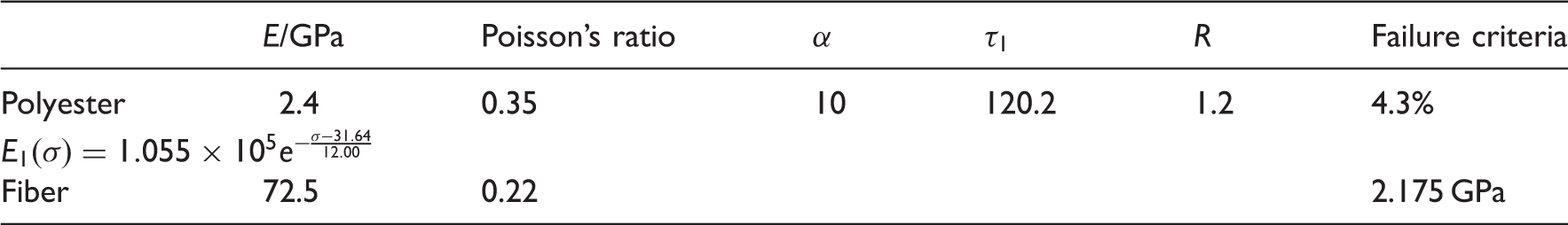
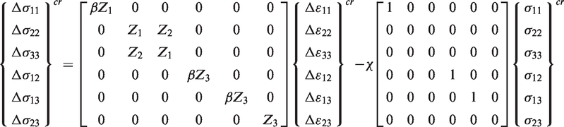
In the above multiscale FEM analyses, if the stress/strain state of an element reaches failure value, a crack is assumed to be initiated in the direction perpendicular to the principal/normal direction. Instead of using element death technique commonly provided in commercial FEM codes, a postdamage constitutive model based on smeared crack concept is used in the current analyses (Jia et al., 2013b). As shown in Figure 7(a), if a crack initiates in the plane perpendicular to the local principal direction 1, the element will not have load bearing capacity in the cracked plane, i.e. the stress components, σ11, σ12, and σ13 must be zeros, but the element can still take other stress components. Therefore, for the pure matrix element in either micro-RUC or meso-RUCs, the postdamage relation in the local principal coordinate system is expressed as
Local cracks in matrix impregnated fiber tow.

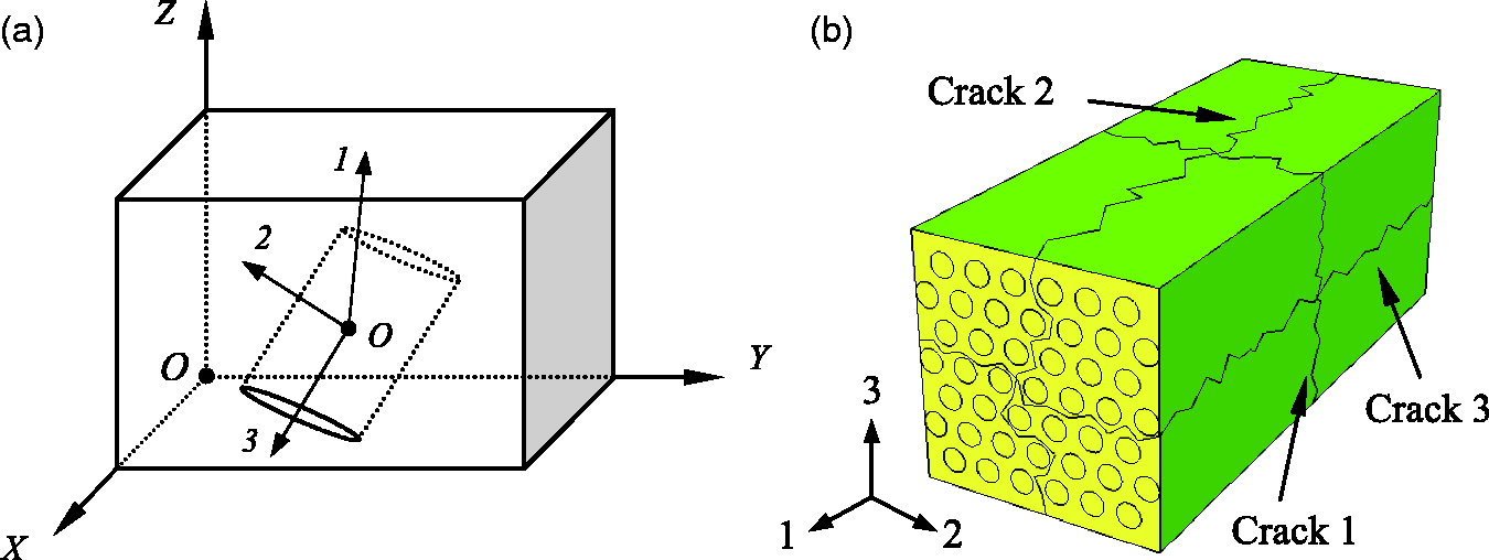
At meso-scale level, the fiber tows are damaged independently in the form of crack 1, 2, and 3 patterns as shown in Figure 7(b). For an example, assuming the 1-direction is the failure direction, a similar postdamage constitutive model for transversely isotropic fiber tows can be represented by
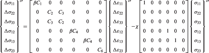
Note that equations (8) to (12) are expressed in the local coordinate system. If the local coordinate system is different from the global coordinate system where FEM analyses is carried out, equation (8) must be transformed to the global coordinate system as

Switch rule
For a general loading path on micro-RUC and meso-RUCs, a stress memory surface is introduced to characterize a loading/unloading case as described (Xia et al., 2005). Initially the von Mises equivalent stress function is defined as
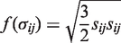
The radius of the memory surface 
Therefore, for a monotonic loading from the virgin state, the stress memory surface will expand with the increasing stress level from location O to location If the current stress point is on the memory surface (like location A) and Schematic representation of switch rule on current stress memory surface for loading/unloading case. If the current stress point is on the memory surface (like location A) and If the current stress point is inside the memory surface, like
where 
Results and discussions
The nonlinear viscoelastic/elastic models with failure criteria for damage and switch rule for loading/unloading analysis were defined by a UMAT and then incorporated into commercial finite element software package ABAQUS/Standard. The PBCs were applied to the micro-RUC and sub-meso-RUCs models with master–slave nodes technique as described in Jia et al. (2012).
Tensile response of resin
From experimental observations (Hu et al., 2003; Shen et al., 2004), the maximum principal strain failure criterion with principal failure strain of Tested and predicted tensile responses of AROPOTM INF80501 at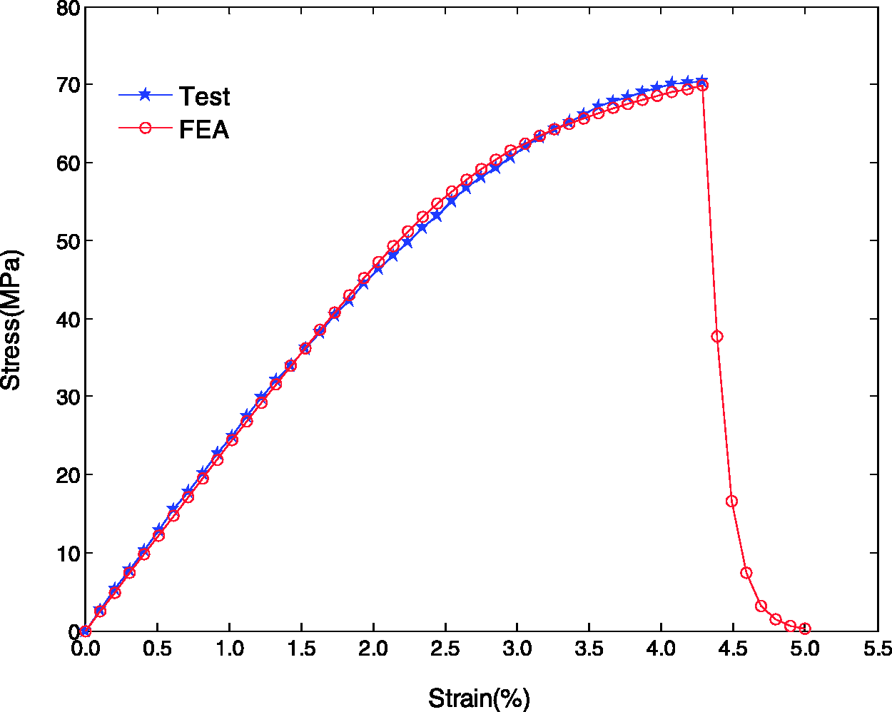
Cyclic tensile response of micro-RUCs
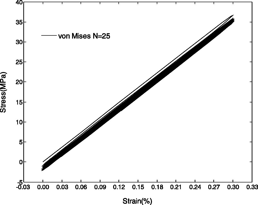
The micro-RUC was loaded in fiber directional Low-cycle tensile behavior of micro-RUC.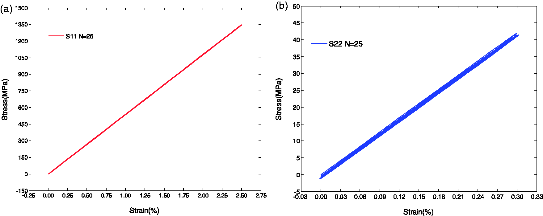
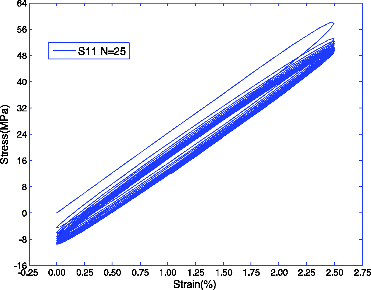
Furthermore, the local node 3868 in matrix was selected as shown in Figure 11 and its cyclic behavior is displayed in Figure 12. The maximum modulus and stress is reached in the first curve and then decreased in successive extension cycling. There is obvious hysteresis loop to be occurred for each cycle. The area of hysteresis loop means the energy has been absorbed by matrix in resin-rich pocket among fibers.
Local stress distribution of micro-RUC in second loading cycle ( Low-cycle response of node 3868 along fiber direction (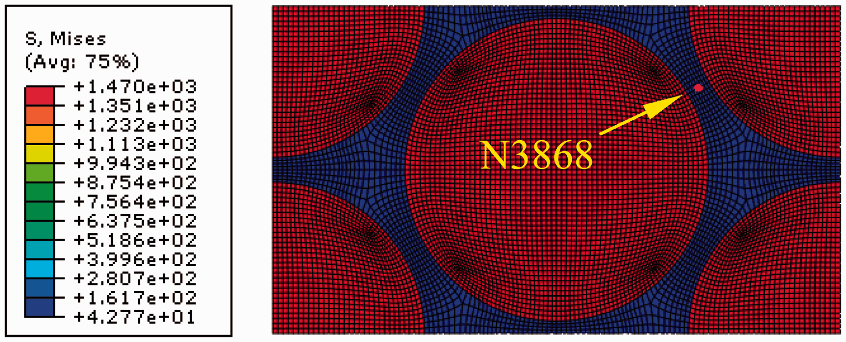
For transverse directional loading case in Figure 13, the stress/strain hysteresis loop during cyclic loading is shown in Figure 14. It has the similar mechanical behavior with that in Figure 12. Upon further loading, the mechanical properties of matrix in micro-RUC degrade progressively.
Local stress distribution of micro-RUC in second loading cycle ( Low-cycle response of node 3868 in transverse direction (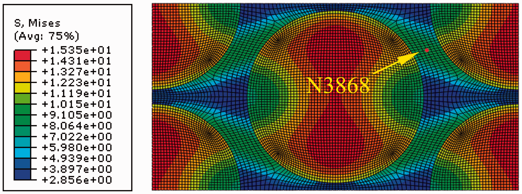
The matrix impregnated fiber tows have distinctive stress distribution along fiber direction and transverse direction shown in Figures 11 and 13, respectively. No obvious stress concentrated area in micro-RUC is occurred in 1-direction and the higher stress located zone is observed under transverse direction.
Elastic parameters being predicted for micro-RUC.
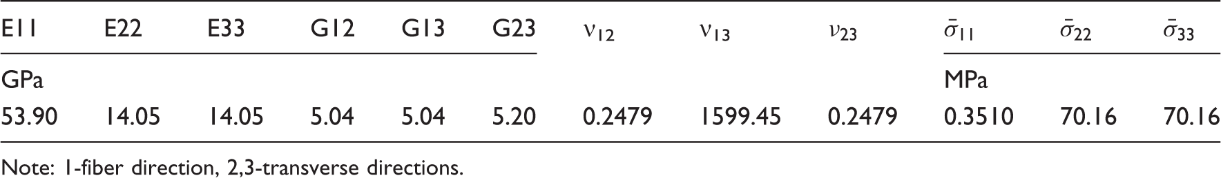
Note: 1-fiber direction, 2,3-transverse directions.
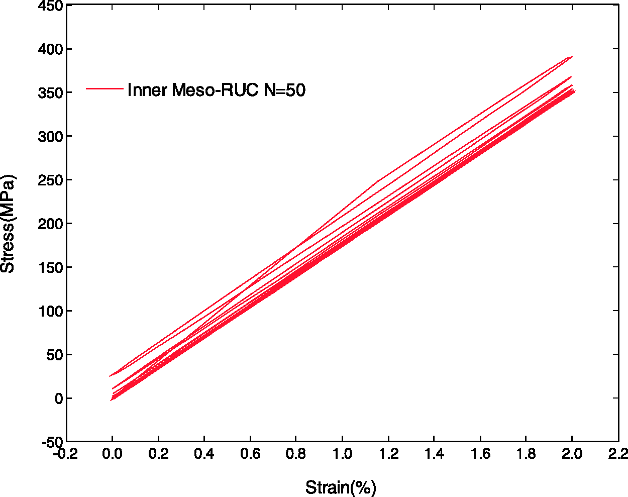
Cyclic tensile responses of inner meso-RUC
Figures 15 and 16 show the cyclic tension fatigue behaviors of inner meso-RUC. In case of Low-cycle tensile behavior of inner meso-RUC ( Low-cycle tensile behavior of inner meso-RUC (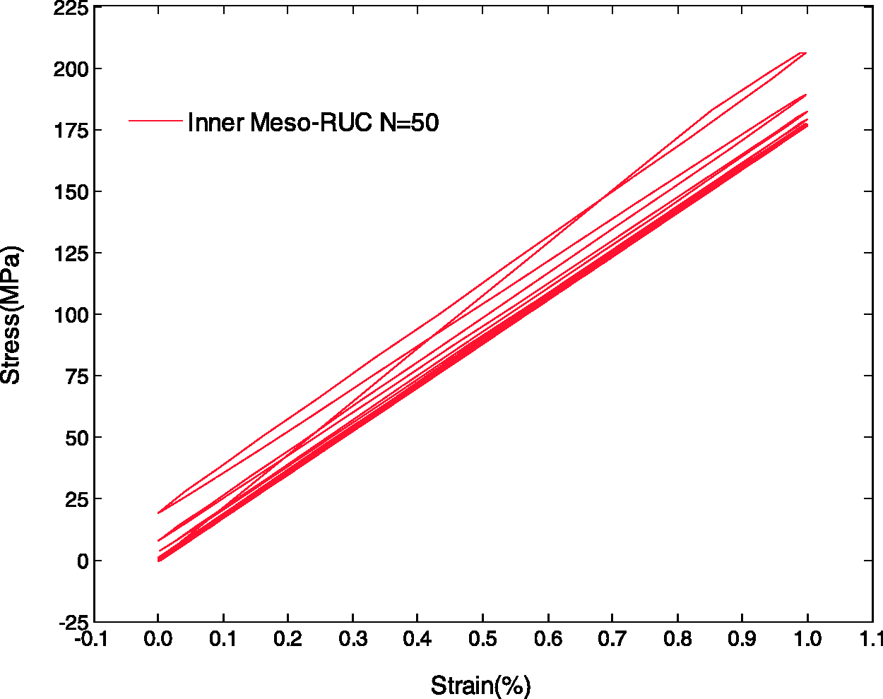
To investigate the local responses of matrix impregnated fiber tows and matrix in inner meso-RUC, three nodes are selected: node 4124 in warp yarns, node 4379 in weft yarns, and node 3686 in matrix under loading path of cyclic tensile strain of Local stress evolution in inner meso-RUC at 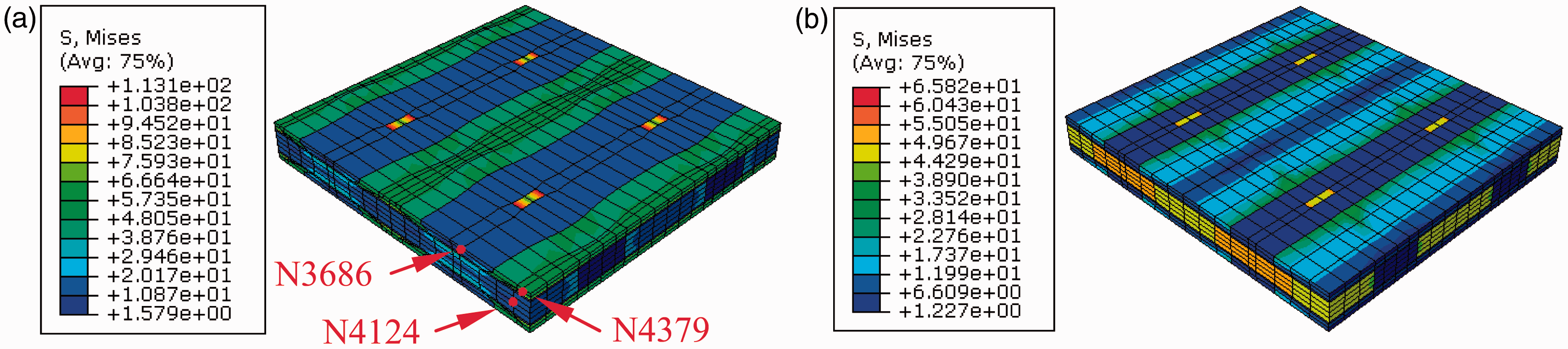
For the first node 4124 in warp yarns, Figure 18 shows the cyclic responses in warp yarns direction paralleled to the cyclic loading direction, and transversely. In Figure 18(a), the matrix impregnated fiber tows behave like a gradual reduction of peak stress and increase of permanent extension in successive cycles of simple extension cycling. For transverse responses in Figure 18(b), warp yarns are under cyclic compressive loading in transverse direction (S22) for first few cycles and then cyclic tensile loading in successive cycles. For another transverse direction (S33), the cyclic tensile response increases with increase of loading cycles with structural effect of yarns in inner meso-RUC and time-dependent distinction of matrix. As the increase of loading cycles, the cyclic responses become stable in transverse directions.
Low-cycle responses of node 4124 in warp yarn.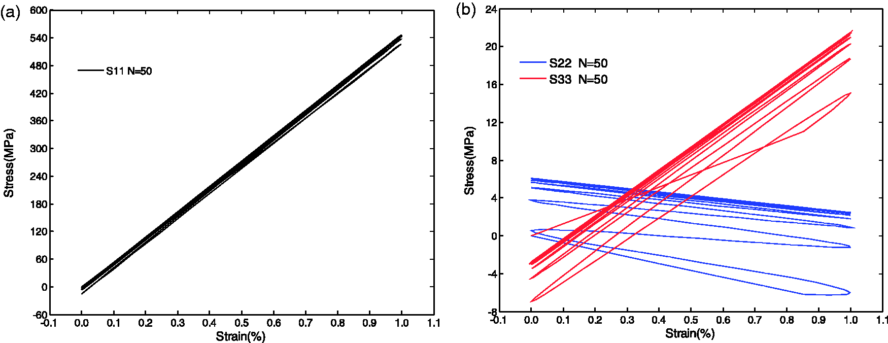
For second node 4379 in weft yarns in Figure 19, weft yarns hold obvious cyclic compressive loading along 1- (in fiber yarns direction) and 3-directions (in thickness direction of inner meso-RUC). For weft yarns in 2-direction, the mechanical response (S22) is shown in Figure 19(b), the peak stress of Low-cycle responses of node 4379 in weft yarns.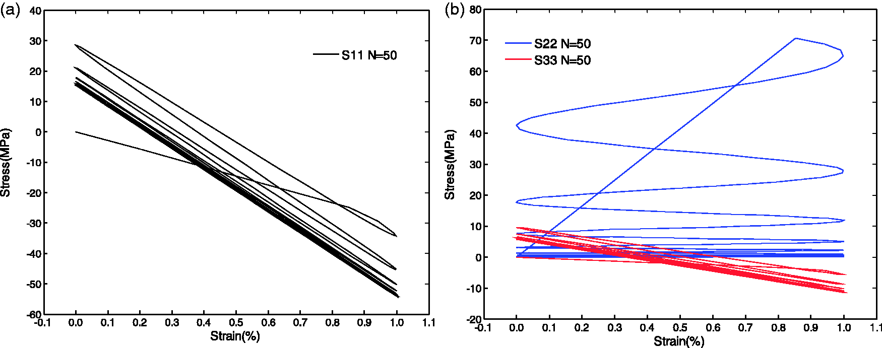
For the last node 3686 in matrix, the peak stress for S11 (in Figure 20(a)) and S22, S33 (in Figure 20(b)) progressively decreases owing to stress relaxation. There are not matrix failures because the applied maximum strain is less than the failure strain of the matrix.
Low-cycle responses of node 3686 in matrix.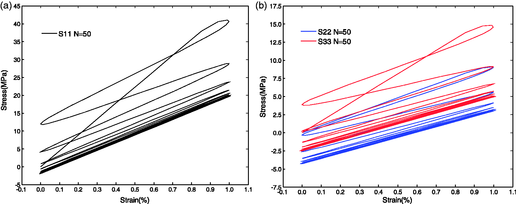
Cyclic tensile response of surface meso-RUC
The surface meso-RUC shows the cyclic tensile loading responses, respectively, in Figures 21 and 22. A similar progressive reduction of modulus and peak stress value was noticed with that in Figures 15 and 16. For Low-cycle tensile behavior of surface meso-RUC ( Low-cycle tensile behavior of surface meso-RUC (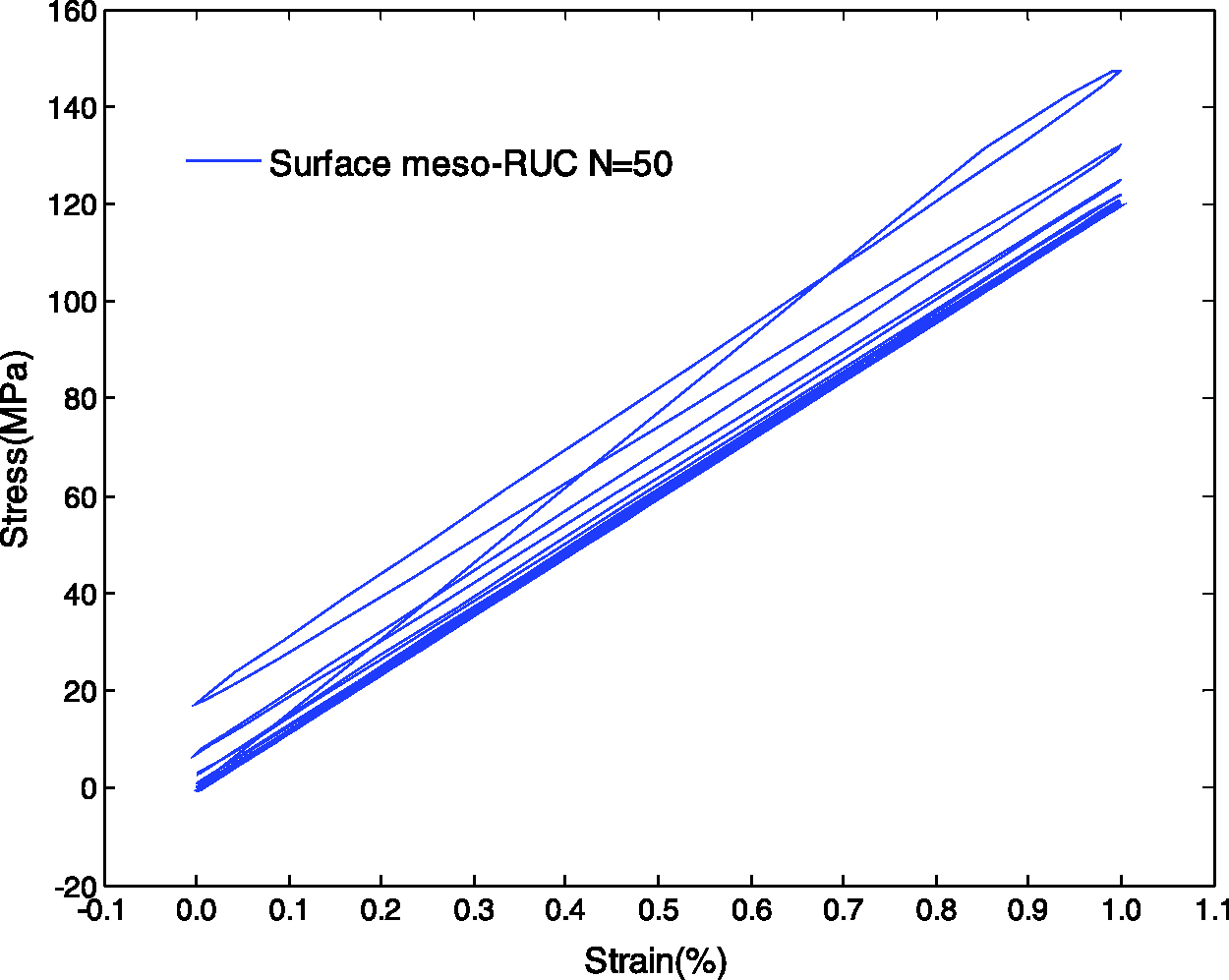
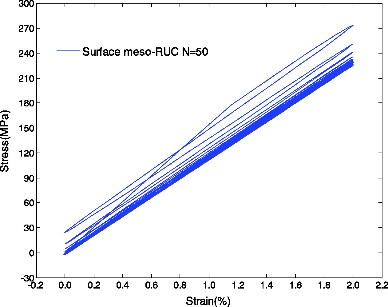
Figure 24 shows the local cyclic response of node 241 (in Figure 23(a)). The middle regions of Z-yarns nearby surface layer are under cyclic loading. The load (S11) along fiber direction progressively decreases owing to stress relaxation in resin-rich zone around them shown in Figure 24(a). The transverse normal responses (S22 and S33) are in Figure 24(b). The loading (S22) in thickness direction of surface meso-RUC is in small stress level due to a thin layer of matrix (with 0.1 mm in thickness direction) in outer surface of surface meso-RUC. With degradation of stiffness for matrix, the stress against strain loop (S33) along weft yarns direction become toward a stable limit.
Local stress evolution of surface meso-RUC at Low-cycle responses of node 241 in Z-yarn.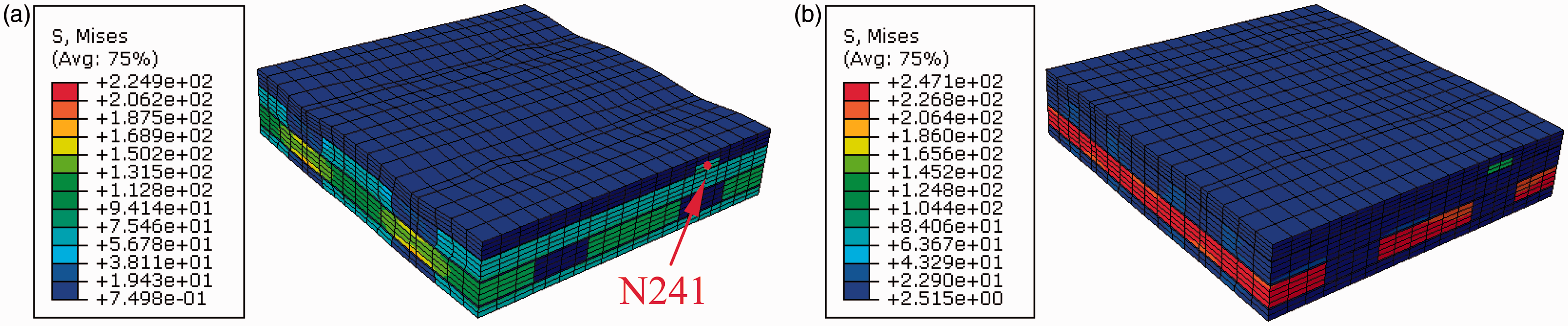
Cyclic tension responses of full meso-RUC
From the predicted results of inner meso-RUC (in Figures 15 and 16) and surface meso-RUC (in Figures 21 and 22), the cyclic responses of the full meso-RUC (in Figure 4(b)) along warp yarns directional loading were obtained. The full meso-RUC includes 14 layers of inner meso-RUC (in Figure 5(a)) and two layers of surface meso-RUC (in Figure 5(b)). The low cyclic behavior of full meso-RUC was obtained with loading path of Low-cycle tensile behavior of full meso-RUC (
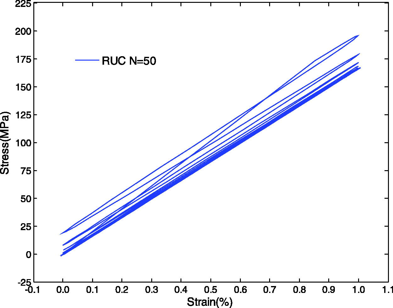
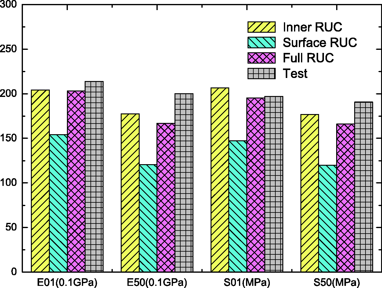
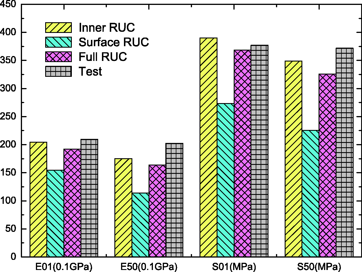
Similarly, the cyclic tensile response of full meso-RUC at Low-cycle tensile fatigue behavior of full meso-RUC ( The averaged modulus and stress of RUCs and 3DOWC in warp yarn direction ( The averaged modulus and stress of RUCs and 3DOWC in warp yarn direction (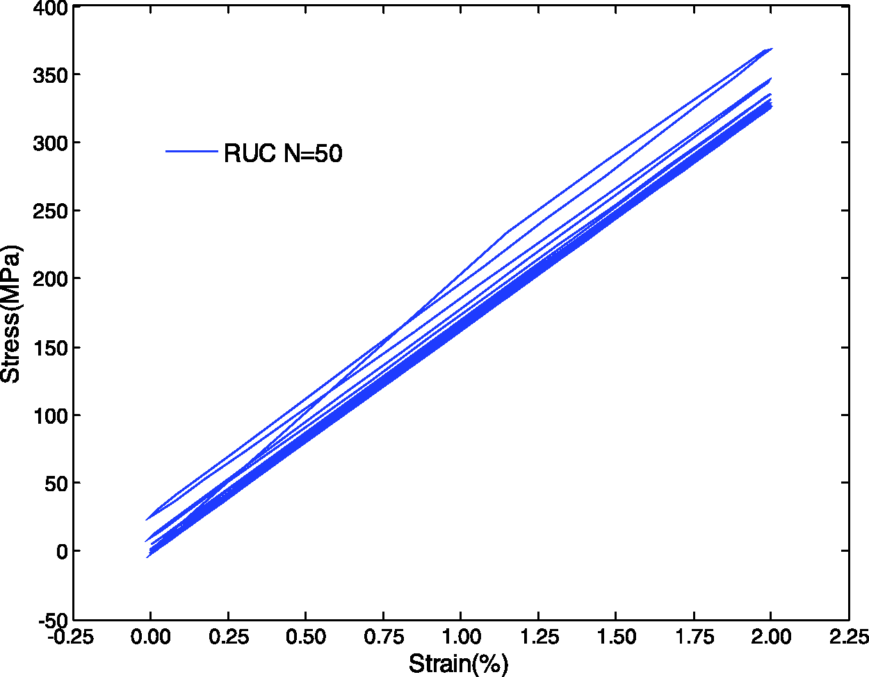
Conclusions
The low-cycle tensile behaviors of 3DOWCs were investigated combined with multiscale finite element analyses (FEA) from fatigue model and experimental results. For the micro/sub-meso-RUCs, their tension–tension fatigue global degradation of stiffness and local decrease of stress peak and the damage were revealed, respectively. Then the low-cycle averaged stiffness decrease of the full meso-RUC was calculated based on mixed rule from inner meso-RUC and surface meso-RUC. These FEA results were verified by experimental in good agreement. As an approach of multiscale FEA with above-mentioned fatigue model, it can be extended to other complex structural composite materials. We hope current approach would be applicable to design other kinds of 3D textile composite materials, for example, 3D braided composite materials.
Footnotes
Acknowledgements and Funding
The authors acknowledge the financial supports from the National Science Foundation of China (Grant Number 11272087). The financial supports from Foundation for the Author of National Excellent Doctoral Dissertation of PR China (FANEDD, No. 201056), Shanghai Rising-Star Program (11QH1400100), and the Fundamental Research Funds for the Central Universities of China are also gratefully acknowledged.