
Abstract
A unified viscoplastic constitutive model with damage is presented to describe creep–fatigue deformation behavior. The primary improvement on the existing models is to introduce creep and fatigue damage variables into the constitutive equations of adapted complexity. The material model, which is developed from the thermodynamic framework, combines nonlinear isotropic and kinematic hardening variables, and is implemented using a user-defined subroutine. A standard specimen and a hollow cylinder are used to carry out uniaxial and multi-axial creep–fatigue tests to validate the material model. Good agreement is obtained between the simulation and the measurement under various thermo-mechanical loading paths.
Keywords
Introduction
As demand for thermal power has increased over the last decade, highly thermally efficient supercritical and ultra-supercritical steam turbines have been developed that use increasingly high levels of steam pressure and temperature. However, the structural strength of the complex components of the turbines, such as the turbine rotors and cylinders, can be affected when the components are subjected to complex mechanical and thermal loadings. For instance, during load changes or startup and shutdown of a power plant, the severe thermal gradients between the inside and outside of components that result from the rapid changes of steam temperature can cause high levels of stress and complex multi-axial stress states. Therefore, the design of high temperature components requires a suitable constitutive material model that can accurately predict stress–strain behavior and fatigue life (Abdullah, 2012; Remy et al., 2013).
Elasto-viscoplastic nonlinear constitutive laws apply in materials where the viscous properties within the plastic range play an important role. Numerous nonlinear constitutive models of elasto-viscoplastic behavior have been established, a detailed description of which is given in paper (Aubertin et al., 1991). One of the first modern elasto-viscoplastic models was proposed by Perzyna (1963) to describe the evolution of viscous effects and hardening. Later, Chaboche (1989) extended Perzyna’s model to establish a model with seven inelastic material parameters, which is described in a paper (Woznica and Klosowski, 2000). Chaboche’s constitutive model is suitable for analyzing a range of small inelastic strains in metals at high temperature (Ambroziak, 2005). The elasto-viscoplastic constitutive equations of Chaboche (1989) have been developed and modified numerous times over the last few decades. The aim has been to develop realistic mathematical constitutive equations to describe the elasto-viscoplastic behavior of materials (Ambroziak and Klosowski, 2007). Furthermore, a recent literature survey (Remy et al., 2013) emphasized the importance of such equations for component design in (1) ensuring the lifespan of components by predicting the initiation of cracks under thermo-mechanical fatigue loading and (2) assessing changes in component dimensions due to creep or ratcheting. As these two goals of component design suggest, an internal damage variable needs to be included in the description of strain versus time or cycles at any location in the component. A detailed literature survey of damage applications in stress–strain behavior is provided in paper (Khoei and Eghbalian, 2012). The existing research includes studies that have modeled fatigue and creep damage by coupling two separate damage variables (Xiao, 2004), developed a coupled damage-visco-plastic constitutive model (Gomez and Basaran, 2005), and explored the relationship between the continuum damage mechanics (CDM) and porous metal plasticity models (Steglich et al., 2005). In addition, various studies (Döring et al., 2003; Oller et al., 2005) have demonstrated the complexity of fatigue behavior under multi-axial loading. Among their other significant contributions, Lemiatre and Chaboche (1990) proposed a damage model for uniaxial cyclic loading that expresses the damage accumulate rate. Other studies (Ambroziak, 2005; Ambroziak and Klosowski, 2007; Ambroziak et al., 2006) have further examined the Chaboche model with damage and implemented the continuum damage in the elasto-viscoplastic constitutive equations into the FE model to provide numerical examples. Recently, Khoei and Eghbalian (2012) established a coupled damage-viscoplasticity model to numerically investigate the evolution of ductile damage leading to failure, wherein the damage variable was derived based on the plastic strain behavior. Remy et al. (2013) improved the viscoplastic constitutive model to overcome the problems encountered in the standard viscoplastic models by, first, improving the reliability of predicting the behavior of cast iron under thermo-mechanical loading and, second, improving the dislocation models to describe the static recovery effects in stainless steels. In addition, the results of studies (Lubliner et al., 1993; McDowell, 1992) demonstrate that it is necessary to adopt a nonlinear kinematic hardening rule to properly simulate experiments on real materials. This is especially true in cyclic loading conditions with plastic stress behavior when simulating ratcheting effects, the Bauschinger effect, or more complex material behaviors (Auricchio and Taylor, 1995; Chaboche, 1991). The Amstrong–Frederick type kinematic hardening model was developed to represent the nonlinear stress–strain relationship. This nonlinear kinematic hardening model was further improved in relation to the dynamic recovery by Frederick and Armstrong (2007). Chaboche and Rousselier (1983, 1986) and Chaboche and Nouailhas (1989) decomposed the nonlinear kinematic hardening terms to extend the validity of the kinematic hardening model to a larger domain of stress and strain, and further modified the Armstrong–Frederick nonlinear kinematic hardening with a threshold in the dynamic recovery term (Chaboche, 1991; Chaboche and Nouailhas, 1989). In addition, Yaguchi and Takahashi (2005) modified their model by using the Ohno–Wang kinematic hardening rules (Ohno and Wang, 1993) to numerically and experimentally investigate the cyclic behavior of modified 9Cr-1Mo steel. A 2008 paper (Chaboche, 2008) provides a detailed literature survey of the plasticity and viscoplasticity constitutive theories of Chaboche.
Chemical composition of X12CrMoWVNbN10-1-1.

Model
Constitutive model
In this paper, the Chaboche–Nouailhas model (Chaboche and Nouailhas, 1989) is used to explain the basic relationships of modeling creep and fatigue behavior. The constitutive equations are based on the additive decomposition of the strain rates into their elastic 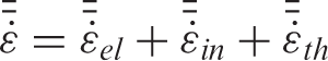
For the expansion part, the thermal strain is defined as,
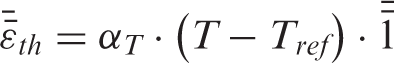

In equation (4), 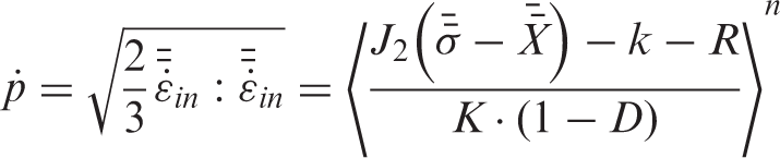
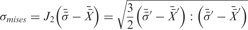
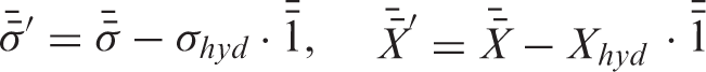
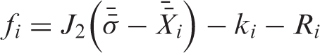
Yield condition
In this paper, a typical Mises yield criterion, which is based on the thermodynamic forces associated with two internal state variables, 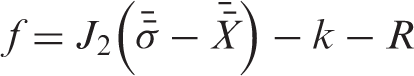
When
Isotropic and kinematic hardening
Isotropic hardening R describes the change that occurs in the equivalent stress by defining the size of the yield surface as a function of the accumulated plastic strain. In this paper, isotropic hardening is deduced as follows:
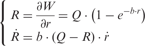
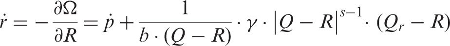

Considering the influence of the damage variable on the isotropic hardening rate, isotropic hardening rate has been refined as,

Tension–compression testing typically reveals the Bauschinger effect, where the plastic deformation increases the yield strength in the direction of the plastic flow and decreases it in the reverse direction. The kinematic hardening model is appropriate for representing this phenomenon. The kinematic hardening tensor 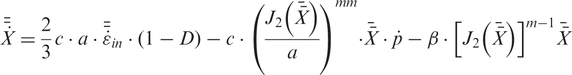
Unified viscoplastic model
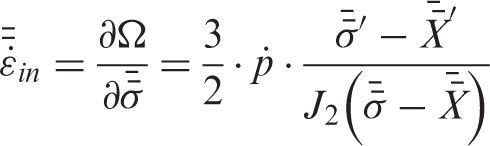
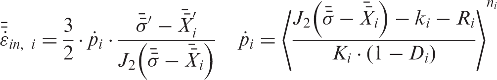
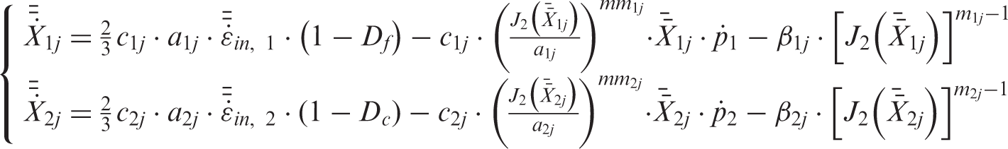
Chaboche proposed the well-known unified viscoplasticity model. First, viscoplastic strain can simultaneously represent both the plastic strain and the creep strain. Consequently, the strain does not exhibit a discontinuity under different types of loading. Second, the viscoplasticity model employs the same hardening rules as the time independent plasticity rule. In addition, under creep–fatigue loading, creep is dominated by diffusion mechanism for low stress, whereas for high stresses, creep is controlled by dislocation mechanism. To enable a more accurate description of the creep behavior, creep is represented by the sum of the two inelastic strain rates. Based on above-mentioned equations, the unified viscoplastic model developed in this paper is given by the following equations,

Results and discussion
A standard specimen and a hollow cylinder were used for the uniaxial and multi-axial creep–fatigue tests, respectively. The unified viscoplastic model presented in this paper was programed into the finite element commercial package ABAQUS by UMAT code to numerically investigate the material behavior under the same test conditions. The simulation results were then compared with experimental measurements to validate the model.
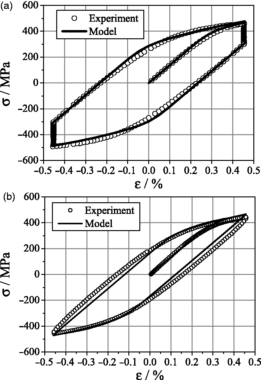
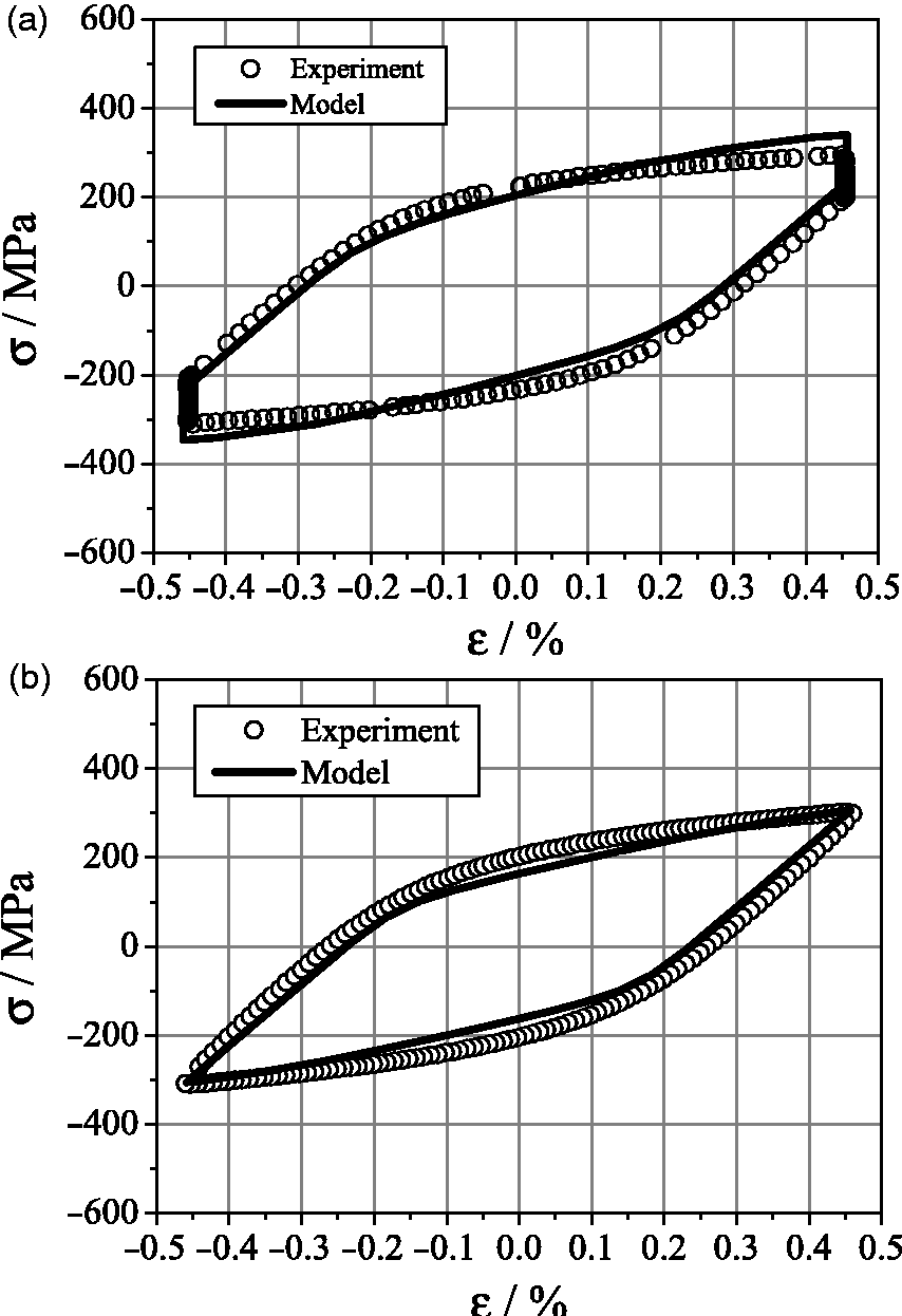
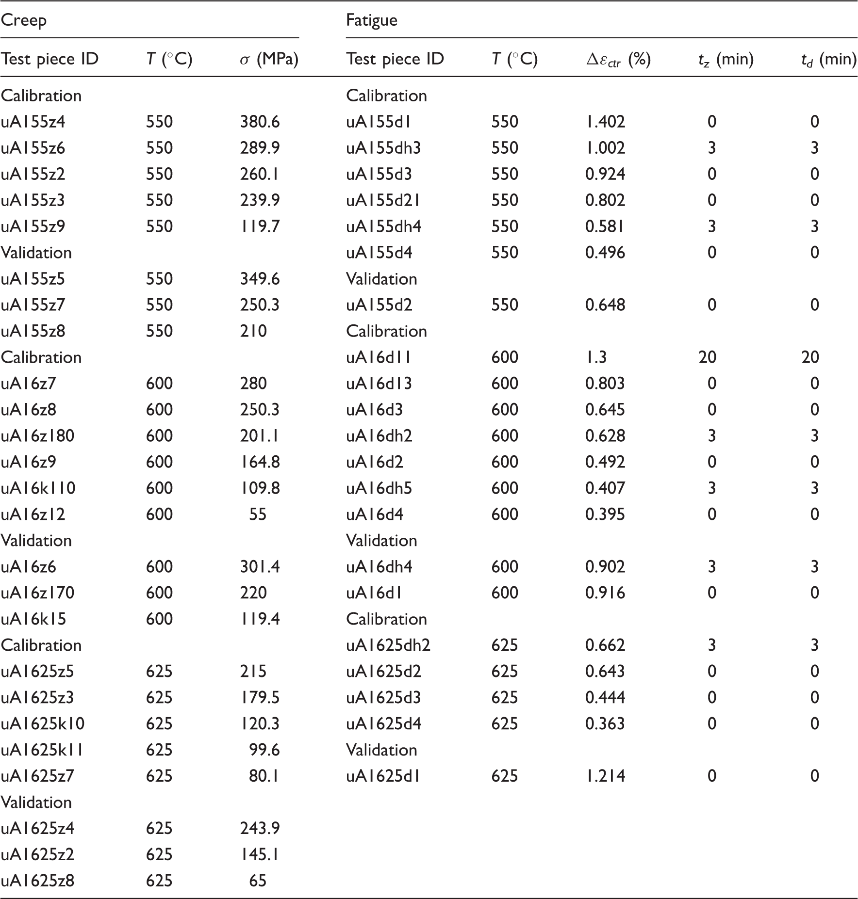
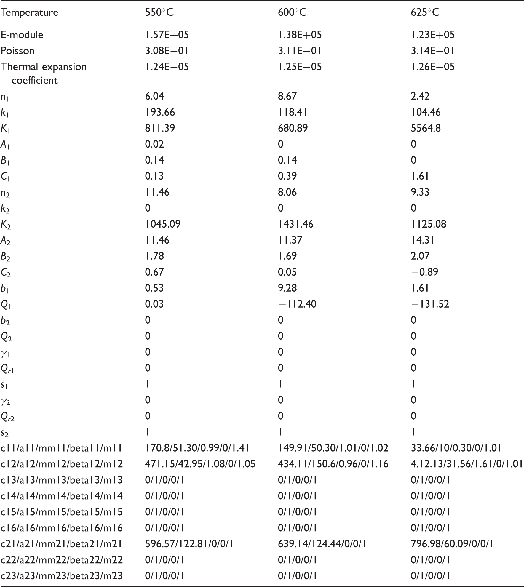
Before examining the stress–strain behavior of the hollow cylinder under multi-axial conditions, experimental data at temperatures of 550℃, 600℃, and 625℃ and under different loading conditions are used to calibrate and validate the viscoplastic model. Model parameters are determined by a software developed at Material Testing Institute in University of Stuttgart – MPA and using a Levenberg–Marquardt algorithm. In identification of material parameters for the model, creep and cyclic hardening/cyclic softening behavior are separately considered. Firstly, experimental creep data are used to identify the material parameters for equations of i = 1. Subsequently, experimental data of the first hysteresis loop is used to obtain material parameters for equations of i = 2 as the procedure of the first hysteresis loop may not generate fatigue damage. Finally, experimental data of cyclic hardening/cyclic softening behavior is used to find material parameters for Df equation. The material model parameters are derived from a comprehensive database that contains experimental data resulting from tension tests, fatigue tests, and creep tests. An overview of the testing conditions for calibration and validation are listed in Table 2. Based on the testing data, the constitutive parameters identified for the model are tabulated in Table 3. Figure 1 plots the simulated and measured results for creep strain over time. Comparison of the simulation and measurement results reveals fairly good agreement. In addition to the creep behavior, further comparison of the simulated and measured hysteresis loops is performed under the testing conditions listed in Table 2 (validation) in order to validate the material model. A strain rate of 0.001/s is used for all cases. Figures 2 and 3 firstly plot the simulated and measured hysteresis loop at the first cycle and the middle lifetime, respectively. Observation of the results shown in Figure 2 displays that the model predicted results agree very well with the test data. Examination on Figure 3, however, shows that the simulated hysteresis loop mostly matches the experimental data except the slightly overestimated simulation results at the maximum and minimum strain points for the case with holding time (Figure 3(a)). On the other hand, the model predicted results agree fairly well with the experiment for the case without holding time (Figure 3(b)). Comparison depicted in Figures 2 and 3 generally demonstrate that the material model is capable of reproducing the isothermal cycle constitutive behavior for the test conditions studied here.
Comparison of the creep results from the model and the experiment. First hysteresis loops for T = 600℃ under: (a) Hysteresis loops for T = 600℃ under: (a) Summary of testing conditions: creep and fatigue. Identified material parameters in the model.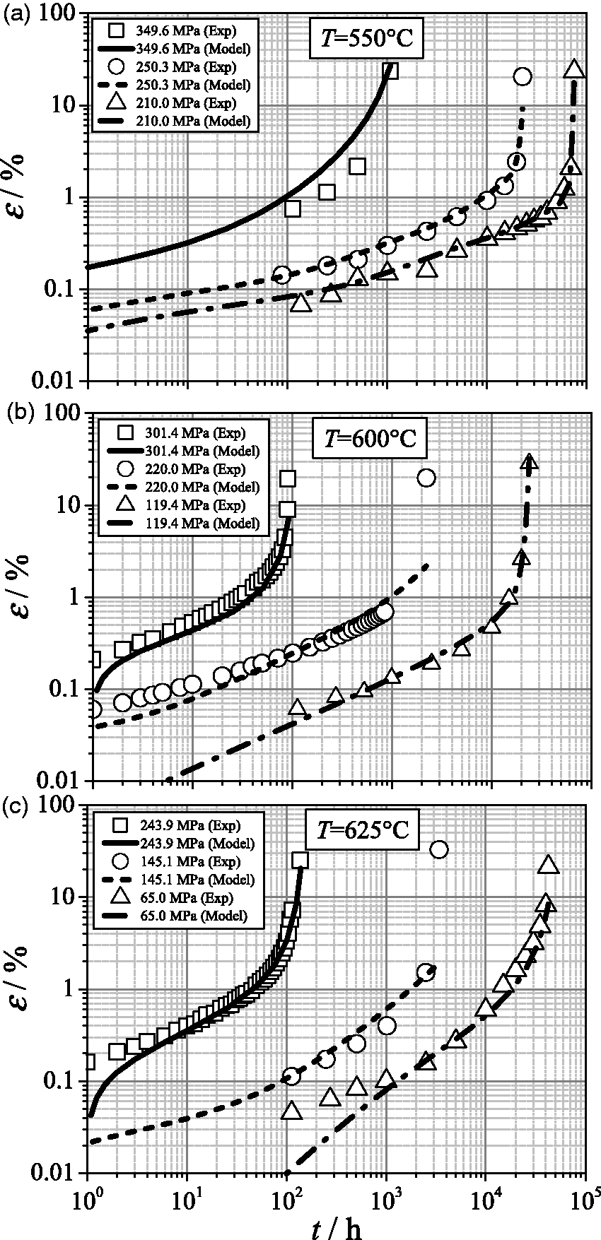
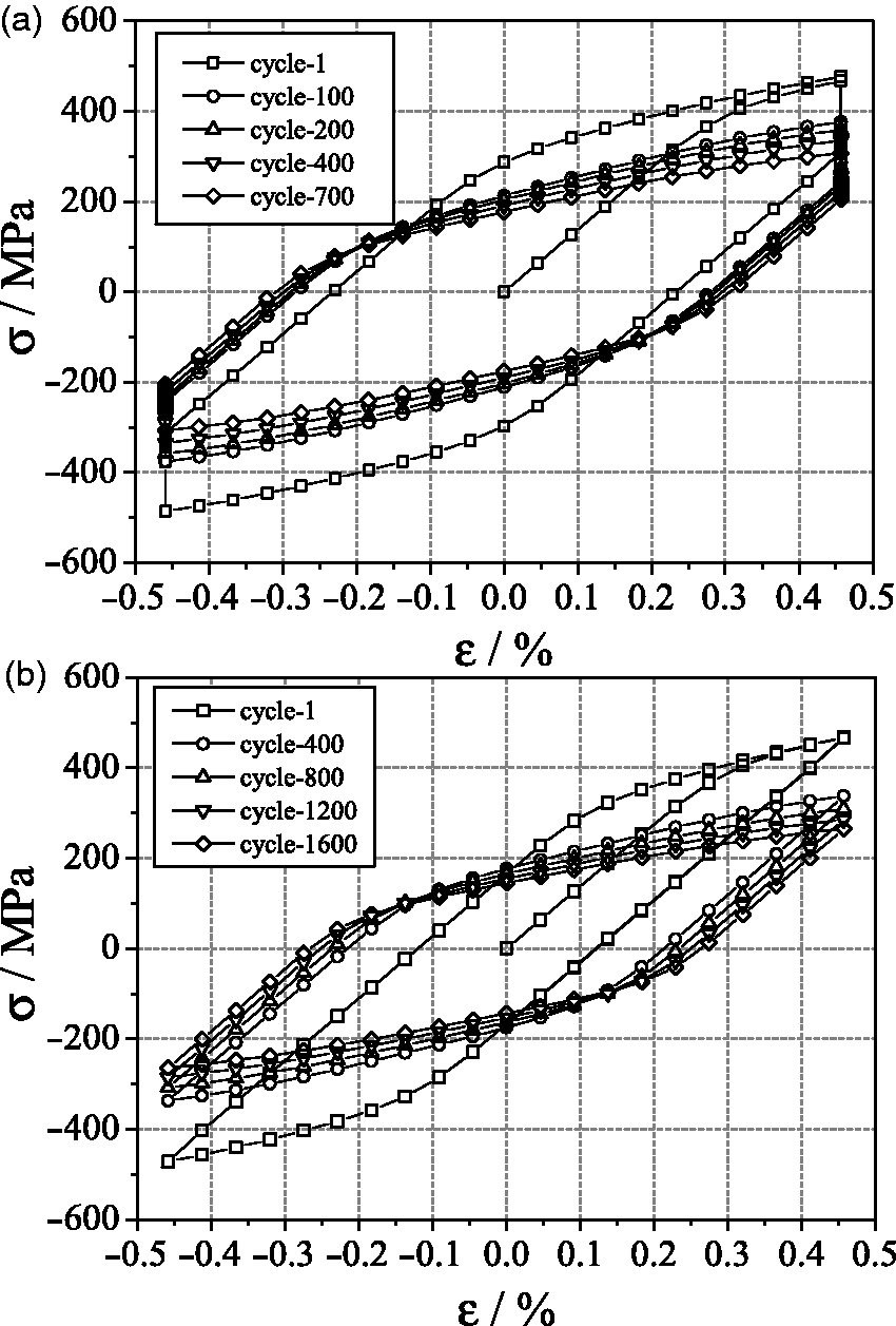
In addition, to illustrate the capability of the material model in predicting cyclic hardening/cyclic softening behavior, Figure 4 compares the evolutions of simulated and measured cyclic stresses at the same conditions. Measured results only give the peak stresses, whereas the simulated results exhibit all of the stresses, including the tensile and compressive peak stresses. As shown in Figure 4(a), the simulated and measured results present a reasonable agreement in the general evolution of material behavior for the case with holding time. Only a slight underestimation exists at the tensile peak stresses. Figure 4(b) displays the material softening behaviors for the case without holding time, and illustrates a good agreement between the simulated and measured results. Based on results of Figure 4, Figure 5 extracts the cyclic hysteresis loops at different cycles for two cases. For the case with holding time (Figure 5(a)), the peak stress noticeably reduces from 430 MPa to 376 MPa after the initial 100 cycles. The decrease in peak stress is only 27 MPa between the 400th and the 700th cycle. In Figure 5(b) (without holding time), the peak stress reduces from 467 MPa to 337 MPa after the initial 400 cycles, and the decrease in peak stress reaches as high as 130 MPa. However, from the 1200th cycle to 1600th cycle, the decrease in peak stress is only 20 MPa. These results demonstrate that significant material softening occurs at the beginning of fatigue cycles, and then the stress decreases slowly during the subsequent fatigue cycles.
Tensile and compressive peak stresses for T = 600℃ under: (a) Cyclic hysteresis loops for T = 600℃ under: (a)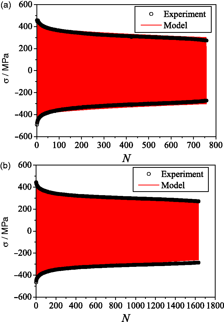
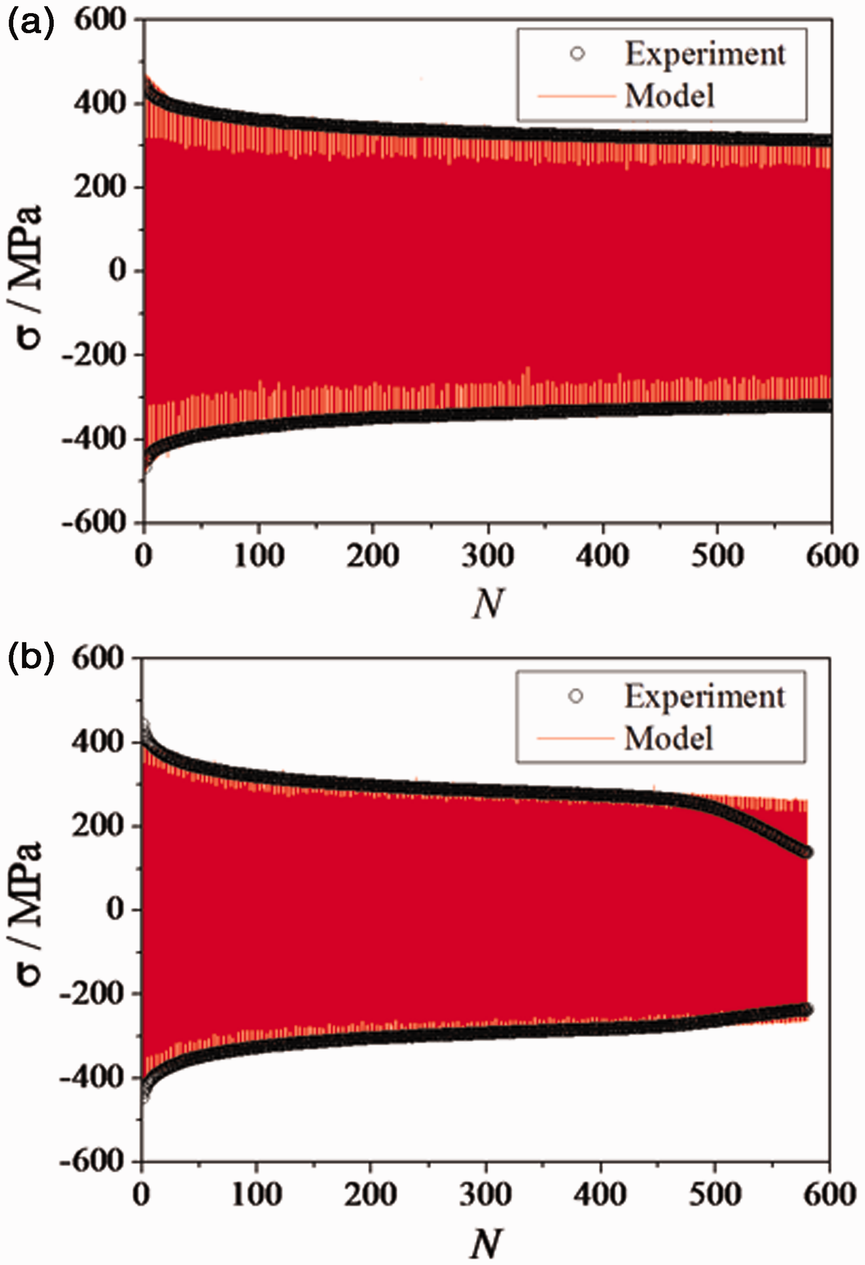
Subsequently, to show the capability of the material model to predict material behavior under other temperatures and loadings, numerical and experimental investigations of creep–fatigue were conducted under conditions of T = 550℃, First hysteresis loop for: (a) T = 550℃, Tensile and compressive peak stresses for: (a) T = 550℃, 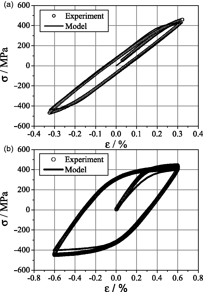
A Thermo-Mechanical Fatigue (TMF) experiment was carried out to demonstrate function and performance of the present model in predicting the material behavior during temperature variation. The experiment was performed under a strain rate of 6%/min, and temperature varied between 300℃ and 600℃. The increase rate of temperature was 21℃/min, and −10℃/min was set up during the process of the temperature decrease. A period for each cycle is 3.2 h. The total strain Comparison between model and experiment under thermo-mechanical loading according to uA16b2 (Cui et al., 2013).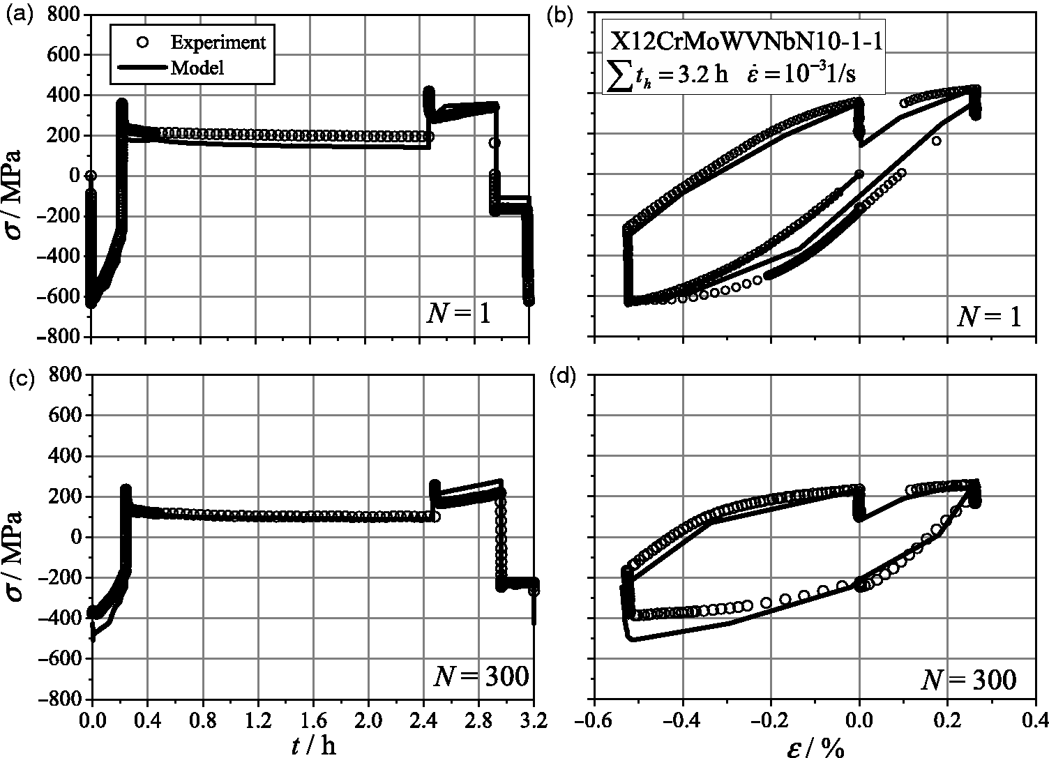
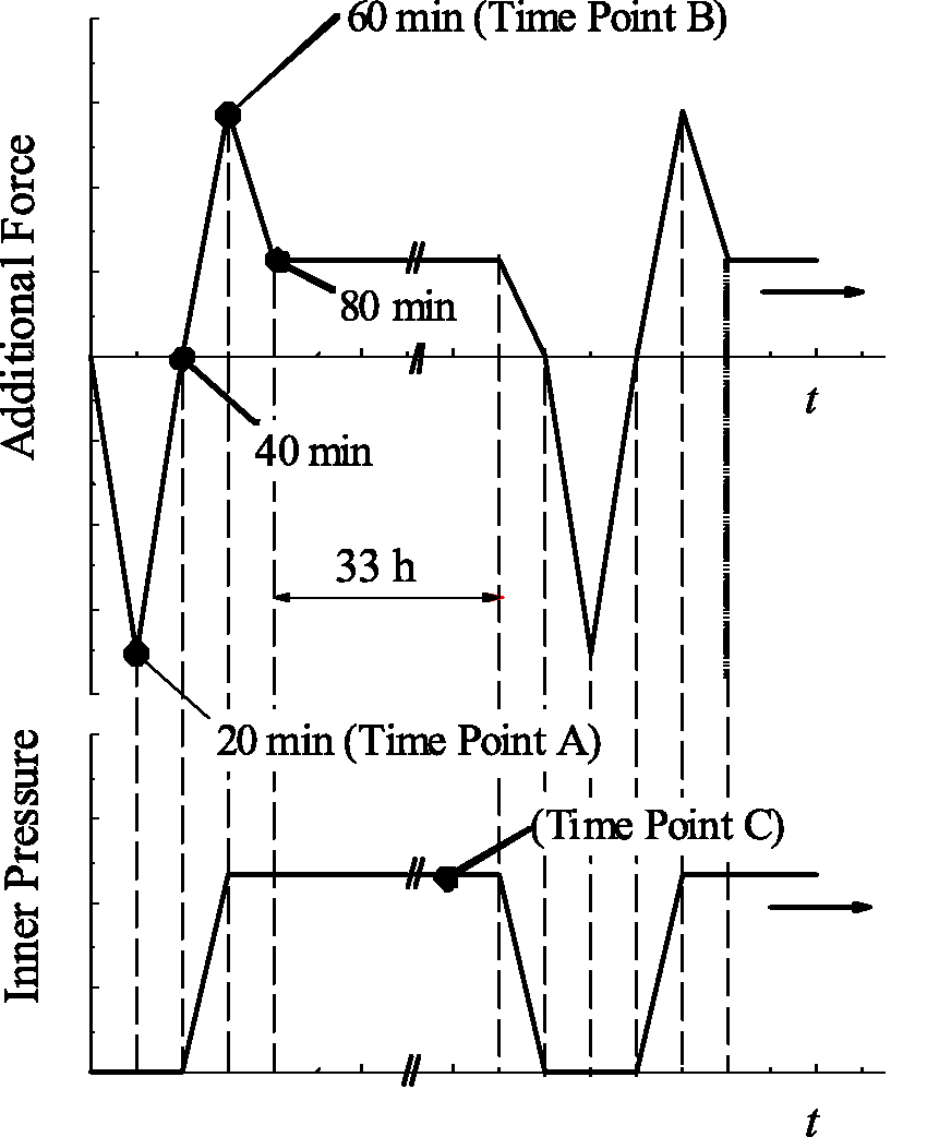
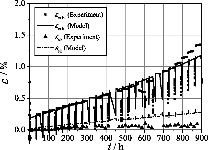
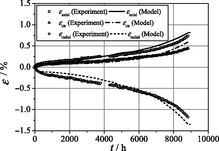
Numerical and experimental investigations of multi-axial creep–fatigue were conducted using a hollow cylinder subjected to a combined loading of internal and axial forces. Geometry of the hollow cylinder and the loading paths are shown in Figures 9 and 10, respectively. Table 4 lists the experimental conditions. Comparisons of the simulation and measurement studies are carried out in terms of strains in the radial (radial strain), circumferential (hoop strain), and axial (axial strain) directions, with results shown in Figures 11 to 14. As can be seen from Figure 11, the creep after each loading change leads to increase in the strains, especially in the axial strain, which increase significantly. This reveals that ratcheting effect in a cycle keeps increasing as the number of cycles increases, and this type of interaction between creep and fatigue accelerates the life consumption in sample A43. Comparison of the simulated and measured results show good agreement in axial strain, but simulation in hoop strain is overestimated. Unfortunately, simulation for the radial strain cannot be verified due to the lack of experimental data for sample A43.
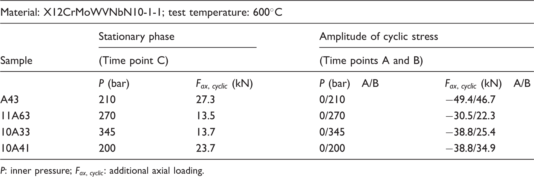
Geometry of hollow cylinder. Loading path of additional force and inner pressure. Strain versus time for the multi-axial creep–fatigue test, sample A43 ( Strain versus time for the multi-axial creep–fatigue test, sample 11A63 ( Strain versus time for the multiaxial creep–fatigue test, sample 10A33 ( Strain versus time for the multi-axial creep–fatigue test, sample 10A41 ( Experimental loading conditions for X12CrMoWVNbN10-1-1 under T = 600℃. P: inner pressure; 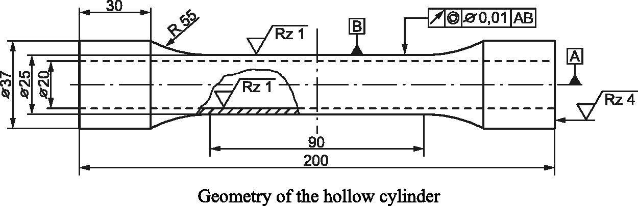
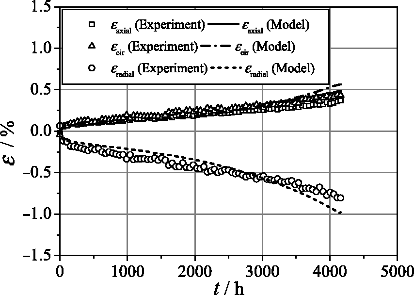
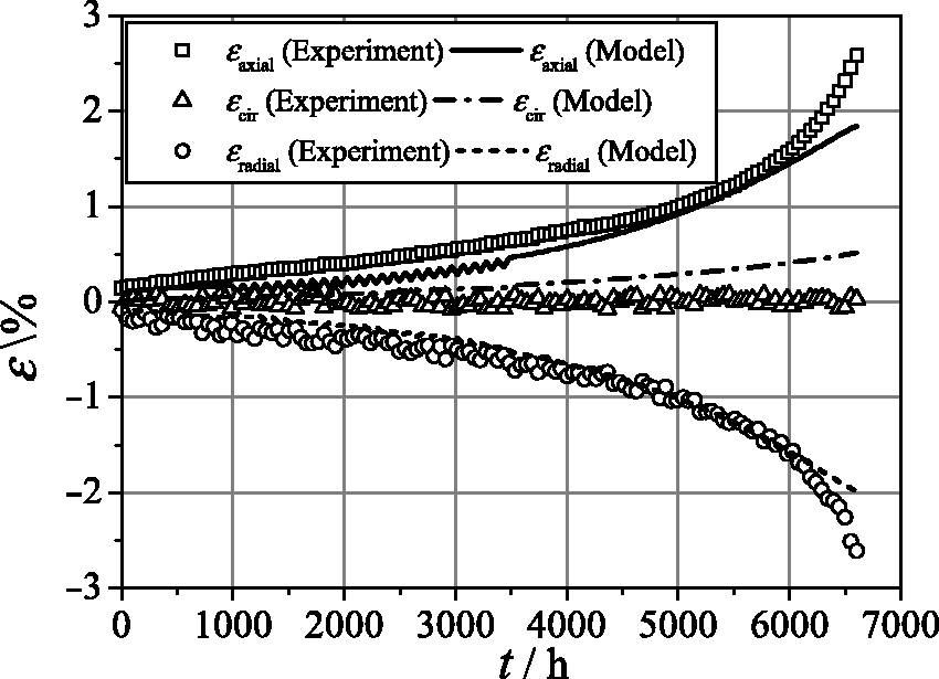
Finally, the stress amplitudes are decreased during the loading cycles to validate the performance of the material model during a longer test period. Figure 12 exhibits the evolution of the strains for sample 11A63, and the test period reaches over 9000 cycles. Observation of the test reveals that no ratcheting behavior is found after each loading change. Thus, Figure 12 only displays the results in relation to the loading change, and it is apparent that the hoop strain deviates from 0 MPa and approaches the axial strain. Similarly, there is also no ratcheting behavior in sample 10A33 after each loading change. Furthermore, Figure 13 show that the evolution of the hoop strain deviates far from 0 MPa, corresponding to the results for sample 11A63, and is approximately equal to the axial strain. For sample 10A41 shown in Figure 14, no ratcheting behavior is observed and the hoop strain approximately equals 0 MPa. Comprehensive study of creep–fatigue damage evolution is performed and the results are illustrated in Figure 15. Rauch (2006) gives the limit curve for nonlinear accumulation of creep–fatigue damage according to ASME code. As seen from the figure, damage of samples 11A63, 10A33, and 10A41 is significantly dominated by fatigue behavior and total damage falls inside the limit curve. Magnified figure displays that evolution of fatigue damage for sample 11A63 is more significant comparing to the results for samples 10A33 and 10A41. Unfortunately, experimental damage was not available for samples, thus the comparison of the simulation and the measurement could not be performed. In addition to the above-mentioned analysis, the results predicted by the material model agree well with the experimental measurements, demonstrating that the material model is capable of reproducing the isothermal creep–fatigue constitutive behavior in multi-axial test conditions studied in the present work.
Evolutions of creep–fatigue damage for samples 11A63, 10A33, and 10A41.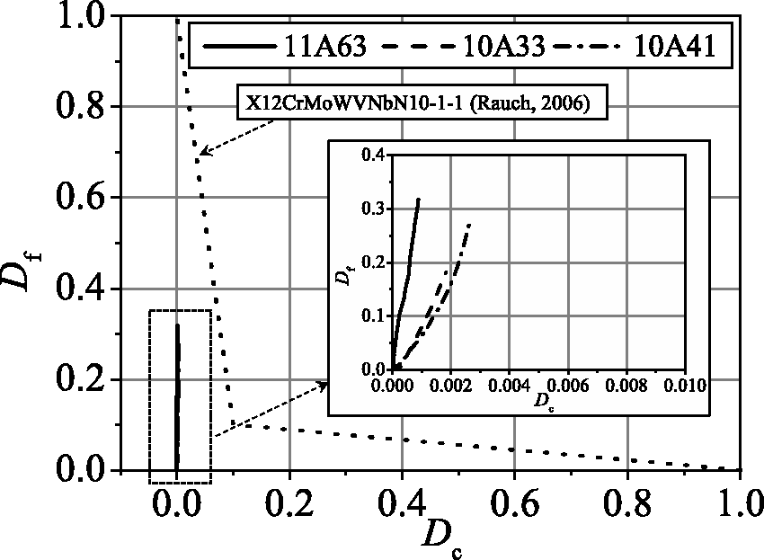
Conclusion
The unified viscoplastic material model with damage presented in this paper was successfully implemented in the UMAT subroutine. In addition to improving the modeling of nonlinear isotropic and kinematic hardening behaviors which could predict the static and the cyclic hardening or softening behavior, a key novel contribution of this study is the inclusion of the creep and fatigue damage variables in the material model. A standard specimen and a hollow cylinder were used to study the uniaxial and multi-axial stress–strain behaviors, and tests were conducted under different temperature and loading conditions to validate the performance of the material model. In the uniaxial loading conditions, the simulation of the material model gave the evolution of the stress–strain behavior in the initial cyclic period and the cyclic softening behaviors, and comparison of the simulation and the measurement showed good agreement in most test conditions. In addition, calculation based on TMF testing condition was performed and comparison between the simulated and TMF testing results showed an acceptable agreement at N = 1 and a deviation at the low temperature in the half lifetime. Similarly, to ensure the applicability of the material model in multi-axial loading conditions, simulation of a hollow cylinder under internal pressure and axial force was performed. The simulation results for the hollow cylinder displayed good agreement with the experimental measurement, indicating that the material model is capable of reproducing the stress–strain behavior in multi-axial conditions. However, the significant discrepancy for the prediction against the test data in the stress–strain behavior was found under the crack openness condition. So, further improvement on the model for the prediction on the crack behavior will be performed in future.
Footnotes
Funding
This research received no specific grant from any funding agency in the public, commercial, or not-for-profit sectors.