






Abstract
Flax fibre-reinforced unsaturated polyester composite laminates were fabricated by vacuum bagging process and their impact and post-impact responses were investigated through experimental testing and finite element simulations. Samples of 60 mm × 60 mm × 6.2 mm were cut from the composite laminates and were subjected to a low-velocity impact loading to near perforation using hemispherical steel impactor at three different energy levels, 25, 27 and 29 Joules. Post-impact was employed to obtain full penetration. The impacted composite plates were modelled with various lay-ups using finite element software LS-DYNA (LS-DYNA User’s Manual 1997) to provide a validated finite element model for the future investigation in the field. The effects of impact and post-impact on the failure mechanisms were evaluated using scanning electron microscopy. Parameters measured were load bearing capability, energy absorption and damage modes. The results indicate that both peak load and the energy absorption were reduced significantly after the post-impact events. Consequently, it was observed from the visual images of the damages sites that the extent of damage increased with increased incident energy and post-impact events.
Keywords
Introduction
Advanced fibre-reinforced polymer (FRP) composites have gained significant popularity in structural applications due to their high strength to weight ratio and superior mechanical properties. However, concerns over global warming and the end-of-life of non-biodegradable carbon and glass fibre reinforcements in composite materials, consumer’s pressure, new government’s legislation and need for light weight structural materials have motivated research into materials which are also biodegradable, renewable and environmentally sustainable (Bledzki and Gassan, 1999; Bolton, 1995; Faruk et al., 2012). As the cost of non-renewable sources of material becomes more expensive, natural fibres can be a viable alternative as reinforcements for composite materials (Adekunle et al., 2011; Dhakal et al., 2007). The use of natural fibres reinforced polymeric composite materials has been successfully used in a wide range of applications in recent years due to their abundant availability, lower density, and much higher specific strength than conventional fibre-reinforced composites (Dhakal et al., 2009; Jacob et al., 2004; Sombatsompop and Chaochanchaikul, 2004). The need for light weight and less CO2 emission structures has large growth potential in demand for natural fibre reinforcements. Therefore, in recent years, automotive industry is leading the way in utilising natural fibre-reinforced composite materials in various non-structural parts such as door trim panels, parcel shelves and other interior parts. However, there are still significant barriers for structural and semi-structural applications of these composite materials due to their vulnerability to low velocity impact damage, lower stiffness among other mechanical properties (Bledzki et al., 1999; Gassan and Cutowski, 2000). Also, their property variability, inherent moisture absorbing characteristics can lead to poor fibre matrix interaction causing reduced composite properties and thus, affecting the long-term performance (Dhakal et al., 2013). For these composites to be used in structural components, it is important that the designers and manufacturers understand how these materials behave under different loading conditions including fracture toughness, fatigue and their impact loading.
Low velocity impact damage can take place in composites when the objects such as runway debris and hand tools fall down on composites during their service life, which cause different failure modes such as matrix cracking, delamination at the interface, fibre breakage and fibre pull-out (Dhakal et al., 2007). Therefore, understanding the characterisation of the effects of various failure modes due to the low velocity impact is necessary in a natural fibre-reinforced composites in order to ascertain the capability of the composites to withstand impact load during their service life (De Rosa et al., 2012; Dhakal et al., 2012).
Several studies have been carried out to understand the low velocity impact response of carbon and glass fibre-reinforced composite materials and structures. An in-depth review undertaken by Cantwell and Morton (1991) has helped researchers to understand the important phenomenon contributing the impact-induced failure of composite laminates. Choi et al. (1991) investigated the impact induced delamination of composites using both experimental and numerical analyses of the damage process. Their work suggested that the understanding of failure of composites due to low velocity impact is always difficult due to several factors involved. Wisheart and Richardson (1999) analysed the impact response of complex geometry pultruded glass/polyester composites. Their report suggests that the residual strengths in tension, compression, bending and fatigue life of composite were reduced to varying degrees depending on the dominant failure mode. Mitrevski et al. (2006) studied the influence of impactor shape on the impact damage of composite laminates. Their results demonstrated that the impactor shape plays a big role on the damage response of composite materials.
Similarly, low velocity impact damage response of natural fibre-reinforced composite materials has been subject of many experimental investigations. Bledzki et al. (2007) studied the falling weight impact damage of Abaca fibre-reinforced polypropylene composite and compared with jute and flax fibre PP composites. Benevolenski et al. (2000) investigated the transverse perforation impact behaviour of flax mat reinforced PP composites in addition with discontinuous cellulose and discontinuous glass fibre mat. Santulli (2009) and Santulli and Caruso (2009) studied the falling weight impact damage characterisation on flax/epoxy laminates as well as other bast fibre-reinforced polymeric composites. Their study reported difficulty of predicting impact damage characteristics of natural fibre composites. Ghasemnejad et al. (2010, 2012) studied the effect of stitching on the impact damage behaviour of single and multi-delaminated flax hybrid composite beams. They reported that stitching can significantly improve the energy absorption capabilities of composite structures. It is evident from these literatures that the impact damage characteristics of natural fibre composites with polymeric matrices like PP, epoxy, and unsaturated polyester (UP), have been well studied. However, not much has been reported on the relationship between the impact and post-impact response of the natural fibre composites especially flax/UP laminates in comparison with experimental and numerical results.
In this study, the effect of flax fibre reinforcement on the low velocity impact and post-impact response of flax/UP composites are investigated. For this, the flax/UP composites were impacted at impact energies ranging from 25 Joules to 29 Joules sufficient to create impact damage near perforation, but not full penetration. The post-impact energy of 25 Joules was employed to all impacted specimens to obtain full penetration and the effect of impact and post-impact performance was evaluated in terms of load bearing capability, energy absorption capability and damage modes of the specimens with regards to increasing incident energy using both experimental and numerical finite element analysis (FEA) model.
Materials and methods
Materials
Physical and mechanical properties of flax fibre bundle (Chang and Chang, 1987; Dhakal et al., 2007).

For comparison purpose.
Composite preparations
The composite laminates were fabricated by hand lay-up and vacuum bagging process in plate of 6.2 mm thickness. The fibre weight percentage was 33% and the void content was 5%. The void content was calculated according to ASTM D2734-94 and the percentage of weight was calculated by means of weighing the fibre content.
Drop weight impact test
The low-velocity impact tests were performed using an instrumented Zwick/Roell HIT230F drop weight test machine with an impactor of constant mass 23.11 kg from an initial height of 110 mm with a hemispherical steel tup diameter of 19.8 mm, as depicted in Figure 1. The drop height of the impactor was adjusted to generate 25, 27 and 29 Joules of incident impact energy. The tests were performed on a square specimen of side length 60 mm with 6.2 mm thickness at room temperature. A catcher mechanism was activated to avoid the multiple damage on the specimens. The incident energies were obtained from adjusting the drop height of the impactor and calculated using typical energy equation:
Zwick/Roell HIT230F drop weight impact tower.
Finite element analysis
Finite element modelling
Due to costly and time consuming process of experimental studies, numerical modelling has been performed to introduce a new method on damage analysis of composite structure. In order to create a FE model to predict the post-impact response of composite structures, the composite plates were modelled with lay-ups according to the experimental studies using finite element software LSDYNA (LSDYNA User’s Manual 1997). The size of the composite beam was 60 × 60 mm2 with a thickness of 6.2 mm. All results have been validated against the experiments to prove the accuracy of this method.
The composite plates were modelled with lay-ups according to the experimental studies using finite element software LS-DYNA (LS-DYNA User’s Manual 1997). The size of the composite beam was 60 × 60 mm2 with a thickness of 6.2 mm.
The composite plate was modelled based on Belytschko-Lin-Tsay quadrilateral shell elements. This shell element is based on a combined co-rotational and velocity strain. All surfaces of the model were meshed using quadratic shell element and the size of an element was 1 × 1 mm2 in the middle of plate as shown in Figure 2. The striker was modelled as a rigid block using solid element.
Finite element (FE) model of striker and plate in LSDYNA. (a) Front view and (b) plane view.
The delamination failure mode needs three-dimensional representation of the constitutive equation and kinematics, and cannot be treated in thin shell theory. This failure mode requires micro-mechanical modelling of the interface between layers and cannot be treated in thin shell theory that deals with stresses at macro levels. Thus, debonding and delamination are usually ignored when thin shell element is used to model failure in composite modelling. In this work, post-impact of damaged specimen was modelled using integration point (IP) through the thickness of the element and each IP is used to represent each composite layer. In this case, the thickness of IP layers at those places which are allocated for delamination was reduced to zero. This situation introduces the damaged area between the related layers.
Material model 54 of LS-DYNA was selected to model the damage of flax composite plate. The Chang and Chang (1987) failure criterion which is the modification of Hashin’s (1980) failure criterion was chosen for assessing lamina failure. The post-failure conditions in the Material 54 model are somewhat different from the original Chang-Chang equations. In this model, four failure modes are categorised. These failure indicators are appointed on total failure for the laminas, where both the strength and the stiffness are set equal to zero after failure is encountered. In this model, as described below all material properties of lamina are checked using the following laws to determine the failure characteristic.
Tensile fibre failure mode (fibre rupture). If
Compressive fibre failure mode (fibre buckling). If
After lamina failure by fibre buckling
Tensile matrix failure (matrix cracking under transverse tension and in-plane shear). If
Compressive matrix failure mode (matrix cracking under transverse compression and in-plane shear). If
In this work, the weight factor β which is defined as the ratio between shear stress and shear strength is set to 1. The contact between the rigid plate and the specimens was modelled using a nodes impacting surface with a friction coefficient of 0.30 (Chang and Chang, 1987; Hashin, 1980). To prevent the penetration of the boundary by its own nodes, a single surface contact algorithm without friction was used. To simulate the impact condition, the loading velocity was applied to the rigid striker.
Scanning electron microscopy (SEM)
The fractured surfaces of the impacted composite specimens were examined using a SEM JSM 6100 at room temperature. After adhering to SEM stubs, a thin layer of gold/palladium was applied to the specimens prior to SEM examination.
Results and discussion
Peak load and energy absorption
Summary of impact test results for different samples.


Comparison of load vs. time curves. (a) Just impacted samples and (b) post-impacted samples.
Energy absorption is an important factor that is commonly used to assess the ability of composite to withstand impact force. The influence of post-impact response on the energy absorption for various incident energy levels is shown in Figure 4(a) and (b). The corresponding energy plots from the experimental results obtained show a strong influence on post-impact resistance as indicated by the amount of energy absorbed by the post-impacted specimens. It can be observed from the same figure that the absorbed energy decreased significantly with increasing incident energy level. The 29 Joules post-impacted samples have the lowest absorbed energy compared to all other categories of the samples. This is attributed to lower impact resistance of the samples caused by matrix cracking and fibre breakage at higher incident energy level.
Comparison of energy vs. time curves. (a) Just impacted samples and (b) post-impacted samples.
The average results obtained from the post-impacted specimens (Table 2) show a significant decrease in peak load and energy bearing capabilities for the flax/UP composites compared to just impacted samples. The peak load and energy absorption for the 25 Joules energy flax/UP sample without post-impact were 5324 N and 26 Joules, whereas at similar energy level, for post-impacted sample, the results were 3375 N and 23 Joules, which was decreased approximately by 37% and 12%, respectively. As can be seen from Table 2, at higher energy, i.e. 29 Joules, both peak load and energy absorbed have been reduced significantly as a result of post-impact damage effect. The peak load and energy absorption for the 29 Joules just impacted samples were 5221 N and 31 Joules, respectively, whereas at similar energy level, for the post-impacted samples, the results were 2530 N and 17 Joules, which was decreased approximately by 52% and 45%, respectively. The significant reduction of both peak load and energy absorption of the 29 Joules post-impacted sample is related to the delamination and fibre fracture, considered as classical mode of failure in composites (Jawaid and Abdul Khalil, 2011; Tan and Watanabe, 2012).
Finite element analysis
In Figures 5 and 6, force–time and kinetic energy–time curves of impact and post-impact response of composite plates which were extracted from FEA model are presented. The main reason for difference between FEA and experimental results might come from deletion of elements after failure of all composite layers during the impact simulation. In this case, there is no more resistance against the striker, therefore, few discrepancies are observed between experimental and FEA results. However, the experimental and FEA results of the composite plate have fairly good agreement. Different stages of impact and post-impact process for composite plate are shown in Figures 7 to 9. It is evident that the composite plate absorbed the impact energy with fracture in the middle of composite plate. In comparison with numerical modelling in previous research, new finite element (FE) technique was developed in this paper which modelled the damaged area within composite structures using IPs to control stiffness of elements on the damaged area. Therefore, the proposed model in this paper can be also used for designing and estimating the mechanical performances of damaged composites joints and evaluating the stress trends on the damaged area. This model can be also used for designing and/or estimating the mechanical performances of damaged composites joints and evaluating the stress trends on the damaged area.
Representative force–time curves for impact and post-impact response of 29 J specimens. Kinetic energy dissipation vs. time under impact energy of 29 J. Illustration of element deformation showing hemispherical impact (29 J) on specimen surface. (a) Plane view and (b) side views. Illustration of element deformation showing hemispherical post-impact (29 J) on impacted specimen surface. (a) Plane view and (b) side views. Comparison between impacted plate in experiment and FEM.


Impact damage evaluation
Typical damage patterns of specimens after post-impact loading are shown in Figures 10 to 12. Figure 10 shows damage incurred by samples post impacted at 25 Joules. The depth of impact tup penetration was approximately 21 mm where the tearing of composite, fibre breakage and circumferential fracture lines were also visible. Figure 11 shows damage incurred for 27 Joules post-impacted samples. A similar trend can be observed as it was for 25 Joules sample apart from higher impact tup penetration which was recorded approximately 21.5 mm. In Figure 12, the 29 Joules post-impacted samples show penetrated samples with biggest impact tup penetration depth (24 mm) as an evidence of much larger damage areas. The rear faces of all samples show pyramid protruded fracture as well as tear damaged areas. A similar trend has been reported by Ude et al. (2013) where they have investigated the degree of damage inflicted on the reinforced composite face-sheet and sandwich foam, core materials used in sandwich panels. The extent of damage varies for flax/UP post-impacted specimens depending on incident energy level applied (Table 2). The impacted front and the rear faces of the specimens show that as the incident energy increased, the damage area also increased.
Pictures of post-impacted damage at 25 J. (a) Rear faces and (b) front faces. Pictures of post-impacted damage at 27 J. (a) Rear faces and (b) front faces. Pictures of post-impacted damage at 29 J. (a) Rear faces and (b) front faces.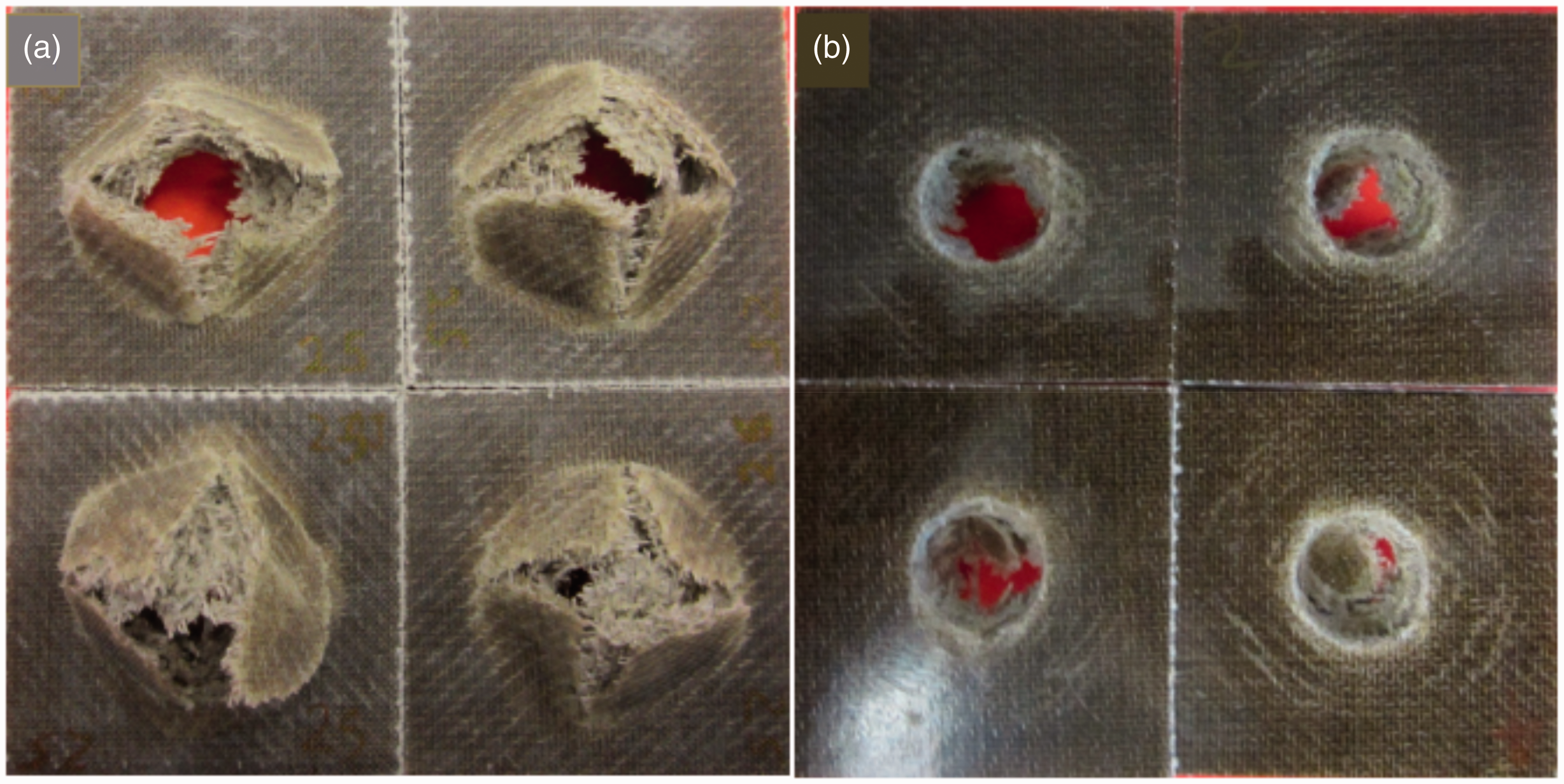


It is noticeable from the post-impacted damage images (Figures 10 to 12) that the extent of damage at the rear faces of all samples is greater than that of front faces as evidenced by matrix cracking and fibres fractures as a result of projectile fully penetrating the composite laminates. Damage incurred on these composites appears to be more local around the impacted site.
Impact response and failure modes of composite specimens were further characterised using SEM. As discussed, the energy used was up to the penetration, the damage mechanisms involved comprise of matrix cracking (Figure 13(a)), matrix cracking and delamination (Figure 13(b)) and fibre breakage and fibre pull out (Figure 13(c)). In this experimental study, the composites were impacted up to penetration and as a result, the damage was clearly visible. But in low velocity impact testing, the specimens were not fully penetrated and specimen failed and delamination occurred. Consequently, the situation can be very dangerous, because they are not easily detected visually and can lead to severe structural failure (Arumugam et al., 2011).
SEM images showing failure modes. (a) Matrix cracking, (b) delamination and (c) fibre breakage.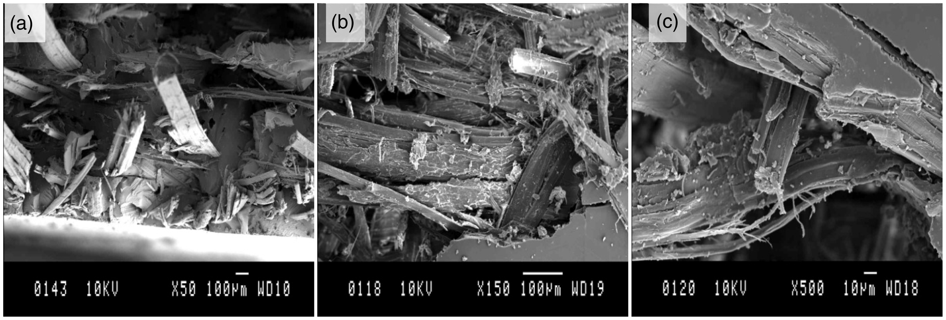
Conclusions
In this study, the effect of post-impact damage on the structural integrity and the damage modes of flax/UP composites were investigated. A comparison between the experimental data and the numerical modelling has been made to measure the post-impact performance. It is evident to conclude that post-impact damage caused a significant load reduction. The peak load and energy absorption for the 29 Joules impacted samples were 5221 N and 26 Joules, respectively. Whereas, at the similar energy level, for the post-impacted samples, the results were 2530 N and 17 Joules, which was decreased by approximately 52% and 21%, respectively. The results showed that post-impact resistance behaviour of flax composites were significantly influenced by the employed incident energy value. For all samples, the damage area increased as the incident energy level increased. The numerical studies in LSDYNA were successfully validated using the experimental data and good agreement was found between experimental and numerical results. This numerical model is capable to predict the impact and post-impact behaviour of composite panels with variable thickness and layups.
Footnotes
Declaration of conflicting interests
The author(s) declared no potential conflicts of interest with respect to the research, authorship, and/or publication of this article.
Funding
The author(s) received no financial support for the research, authorship, and/or publication of this article.