
Abstract
In the creep tests, stress is no longer a constant and increases gradually under the influence of damage occurring during accelerating creep, which is a slow-loading process rather than a conventional creep. With the accumulation of the damage over time, the actual stress increases greatly. The increased actual stress not only generates loading strain but also causes the steady creep rate to rise. This coupling possibly explains why salt rock presents nonlinear accelerating characteristics at the accelerating creep stage. In this work, the constraint of the present creep concept was overcome by assuming that the acceleration creep phase is a coupling process of loading and creeping. Furthermore, we demonstrate that the total strain in this phase is equal to the sum of loading strain and creeping strain. A new nonlinear constitutive equation for creep was then derived, and the mechanisms underlying the nonlinear accelerating characteristics emerging at the stage of accelerating creep are further explained. A step-loading experiment on salt rock was performed for a period of six months. The characteristics of accelerating creep appeared in the last step of loading. This new nonlinear creep damage constitutive model was used to fit and analyze the test data. Obtained results show that this model fits well to these test data and also favorably represents the nonlinear characteristics of accelerating creep, thus supporting the model’s validity.
Introduction
Rheological and time-dependent characteristics are intrinsic mechanical properties of rock (Jiang et al., 2016). With the advancement in technologies applied in underground rock engineering and increasing depth of resource exploitation, many recent studies have focused on the rheological properties of rocks (Vervoort and Declercq, 2018; Zhao et al., 2017; Zou et al., 2015; Zou and Lin, 2018). In particular, soft rocks have prominent rheological properties, which are closely related to numerous engineering problems (Mauricio, 2014; Yang et al., 2017). Salt rock is one of the typical soft rocks and has been recognized as an ideal medium for underground strategic energy storage and high-level radioactive waste disposal. Because of its strong rheological characteristics, investigating the rheological properties of salt rock for the long-term stability and safe operation of underground energy storage is of great theoretical significance and practical value (Xie et al., 2011; Yang et al., 1999).
Rocks, especially deep rocks, constantly experience the effects of external load and gravity. Consequently, all or most rocks may gradually accumulate damage deformation or creep deformation characteristics in the long term, which eventually leads to the damage of various rock structure, causing severe plastic deformation or even progressive failure (Gao et al., 2018; Kim et al., 2016; Mark, 2018; Ren et al., 2017). Although determining the initiation of the creep process of rocks remains a challenging problem, it is essential to investigate rock engineering to ensure safety of production and workers (Wang et al., 2014a; Yang et al., 1999). The creep property of rock is crucial to the long-term stability of geotechnical structures. The time-dependent mechanical behaviors of rocks subjected to a complex geological condition can be described by the creep model, which is the key for stability analysis and safety evaluation. As a result, much effort has been dedicated to the study of creep behaviors of rock, most of which were devoted to modeling the rock creep. Consequentially, various creep constitutive models of rock have been proposed. Based on the Lubby2 rheological model, Lux and Hou (2000) presented a new creep model considering ductile deformation, dislocation, deformation hardening, as well as the mechanism of deformation restoration, damage, and damage recovery by continuum damage mechanics. They successfully applied this model in underground caverns for the storage of toxic and radioactive waste. Shao et al. (2003) established a rheological model for rock behavior by considering the deterioration of elastic modulus and strength resulting from microstructural evolution, which can describe the plastic deformation, damage, volumetric dilatation, and creep phenomena. Shao et al. (2006) studied the anisotropic damage of brittle rock, and introduced a second-order damage tensor model for explaining bonding creep deformation. They suggested that the time-dependent deformation was caused by stress degradation due to continuous propagation of microcracks. Based on the continuum damage mechanics, Wang (2004) proposed a new constitutive creep damage model for rock salt. The internal variable-damage factor and its corresponding rheological deformation were used to analyze the creep damage continuum macro-characteristics of rock salt. Yang et al. (2014) investigated the time-dependent behavior of diabase using a nonlinear creep model by integrating an instantaneous elastic Hooke body, a viscoelastoplastic Schiffman body, and a nonlinear viscoplastic body in series mode. Based on the generalized Hoek–Brown criterion, Ma et al. (2013) described a three-dimensional creep damage constitutive model, which allows to calculate both the three creep phases and the deformation induced by vicious damage and plastic flow. Considering the rheological element, Yang et al. (2010) established a statistical damage creep constitutive model with nine model parameters, all of which were based on the Nishihara model, to analyze the creep deformation of warm ice-rich frozen sand. Based on the internal variable theory, Zhang et al. (2014) developed a creep model with damage, which can preferably describe creep law and thermodynamic properties. A rheological model, accounting for viscoelastic and viscoplastic contributions to rock creep, was established by Sterpi and Gioda (2009). The model also considered the effects of tertiary creep by including gradual mechanical damage dominated by the cumulated viscoplastic strains. To describe the time-dependent mechanical property of rock in the creep course, Wu et al. (2015) proposed a new method for establishing creep model based on variable-order fractional derivatives. The order of the fractional derivative is regarded as a function of time, rather than a constant of arbitrary order. Wang et al. (2014b) studied the creep properties of salt rock subjected to low-frequency cyclic loading and built a creep damage model for salt rock based on the Burgers model. Taking into account the damage and time-dependent characteristics of the rock’s yield strength, Chen et al. (2014) put forward a time-dependent damage constitutive model of marble based on fractional calculus theory and damage variables.
At the stage of accelerating creep, the aforementioned studies demonstrated that damages occurring in internal rocks had been unanimously accepted. Overall, studies on rheological models of rocks have made great progress and have presented many interesting findings. Furthermore, these studies greatly promote the nonlinear rheological theory of rocks by introducing the concept of damage mechanics. However, several problems need to be addressed while applying their results. For example, due to the damages occurring inside rocks, actual stress at the accelerating stage increases gradually; however, in reality, in a creep, strain augments but stress remains constant over time. Therefore, the accelerating creep does not precisely describe the creep defined conventionally. As another example, while nonlinear accelerating characteristics appeared during the accelerating creep phase, the intrinsic reason for such a situation remains unclear? Therefore, to resolve these unanswered questions, the nonlinear creep model remains important for investigating the rheology of rock at present as well as in future studies. In this work, the constraint of the present creep concept was overcome by assuming that the acceleration creep phase is a coupling process of loading and creeping. Furthermore, we demonstrate that the total strain in this phase is equal to the sum of loading strain and creeping strain. A new nonlinear constitutive equation for creep was then derived, and the mechanisms underlying the nonlinear accelerating characteristics emerging at the stage of accelerating creep are further explained.
A new theoretical nonlinear creep damage model
Yang et al. (2002) suggested that a nonlinear hardening phenomenon existed in the stage of rock decay and steady-state creep, with little or no damage inside the rock, which can be neglected. As rocks are continually loaded to the accelerating creep stage, damages increase and display distinct nonlinear characteristics (Nezhad et al., 2016; Pensee et al., 2016). Therefore, we assumed that rocks would not experience damage until entering the accelerating creep stage.
Assuming the damage can be expressed by time, we obtain the following equation

Thus
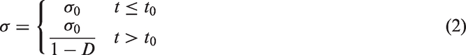
According to equation (2), the actual stress of the creep is depicted in Figure 1.
The actual stress in the creep tests.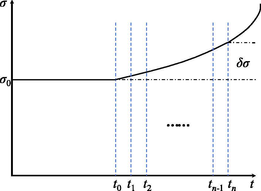
Suppose strain ɛ1 is induced by the loading stress from time t0 to tn

Here the stable creep rate is regarded as a function of the actual stress, that is

Let ti − ti − 1 = δti (i = 1,2,…, n). When δti is small enough, stress approximates a constant from time ti − 1 to ti, corresponding to the stable creep rate of
Note that λ = max {δt1, δt2,…, δtn}, while λ → 0. If ti − ti − 1 = δti (i = 1, 2,…, n), ɛ2 tends to a decided limit, which is also the integral of function

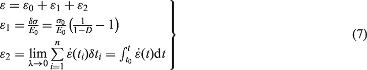
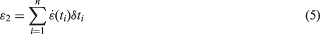
In this work, the accelerating creep stage is considered a coupling process of loading and creep, so it no longer represents the conventional creep process. Equation (7) is the proposed nonlinear creep damage model, where strain ɛ1 is caused by loading stress, and ɛ2 is creep strain.
Experiment of creep
Preparation of specimens
All salt rock samples in this experiment were collected by drilling the surface of Wangchu 1# mine of Jianghan Oilfield in China. These salt rocks are primarily composed of NaCl and some impurities. According to the specific requirements of “Rock Test Code for Water Conservancy and Hydropower Engineering” and “Test Standard for Engineering Rocks,” standard cylindrical specimens of diameter 75 mm and height 150 mm were machined from these drilled samples. Furthermore, the cylindrical surfaces and ends of these specimens were further grinded using a lathe under dry condition, to meet the experimental requirements of flatness and parallelism of two ends, as well as the verticality of specimen axis. Figure 2 shows the preparation process of the samples.
Specimen processing.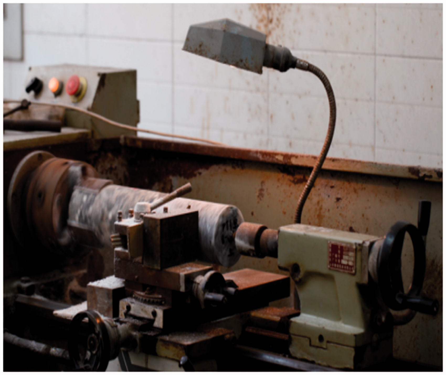
Experimental system
The creep experiment was conducted using a large-scale SPC (namely Stored Program Control) triaxial rheological test system (Figure 3). This experimental system can realize creep under adjustable axial loads from 0 kN to 600 kN, confining pressure from 0 MPa to 30 MPa, and temperature from room temperature to 200℃. With regard to the measurement of axial displacement, two recording methods were applied to guarantee its accuracy. One is the build-in displacement sensor of rheometer, through which data can be automatically transmitted to a computer. The other one is a manually installed dial indicator. Moreover, to reduce the impact of temperature on the creep of the salt rock, two conditioners were installed, which controlled the temperature in room around 20 ± 2℃. Therefore, creep test could be conducted without too much influence of temperature and with reliability.
Experimental system for creep test of rock.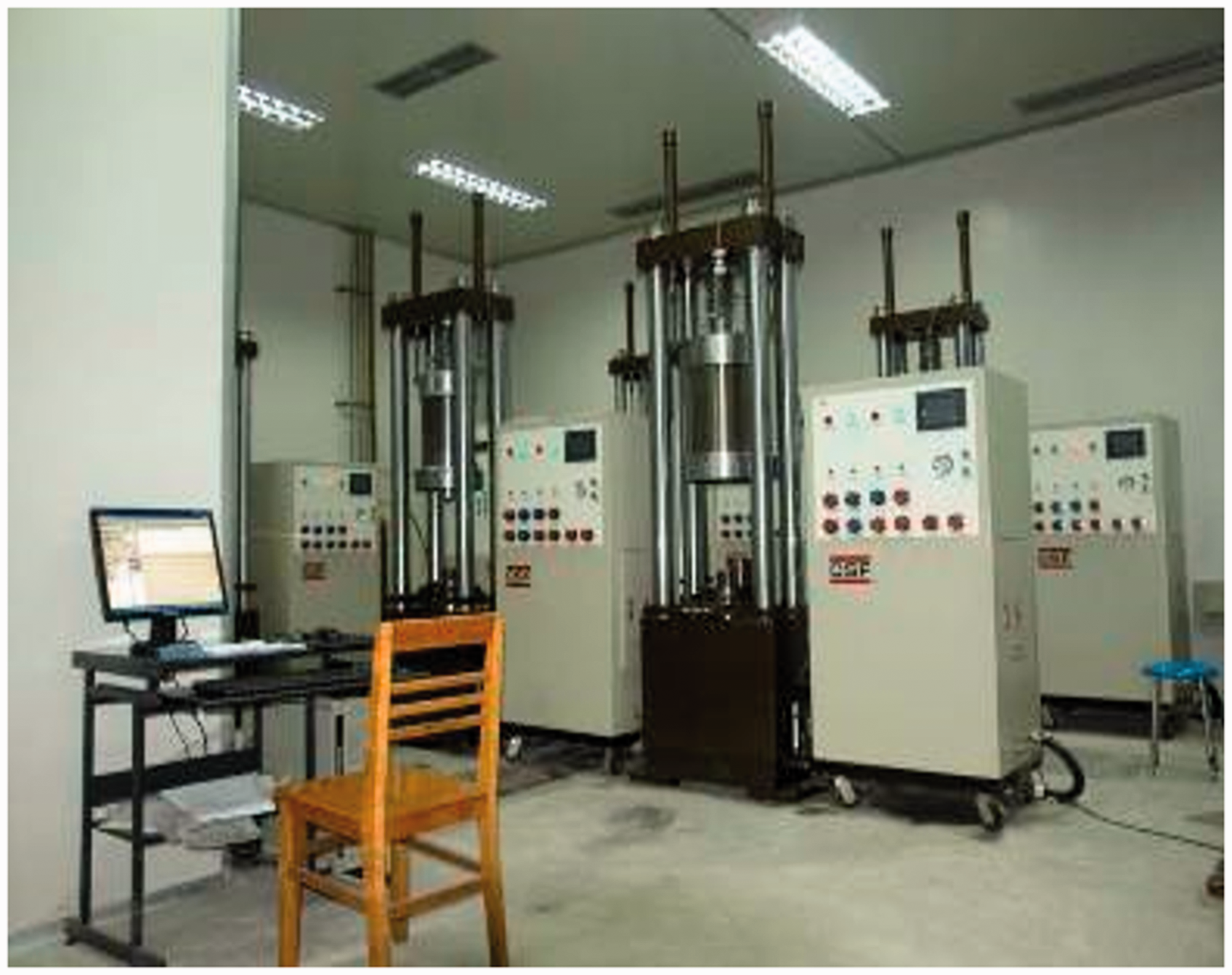
Test approach and procedures
The test steps are as follows: (1) To prevent salt rocks from corroding the pressure head and test machine, all specimens were well wrapped in plastic wraps. (2) These wrapped salt rock specimens were stably placed into the rheological test machine. (3) After placing the specimens appropriately, the axial displacement meter and dial indicator (shown in Figure 4) were respectively installed to record the present axial displacement. (4) The load on the specimen was adjusted to the first predetermined stress of 4 MPa. (5) The computer was started automatically to record data. Meanwhile, data from the dial indicator were also read. At the initial loading stage, the frequency of data recording should be higher, and all data were recorded two times per day during stable deformation. (6) The loading stress was increased by 2 MPa every 15 days until the specimen collapsed, as shown in Figure 4.
Rock sample in creep test and the rock sample after failure.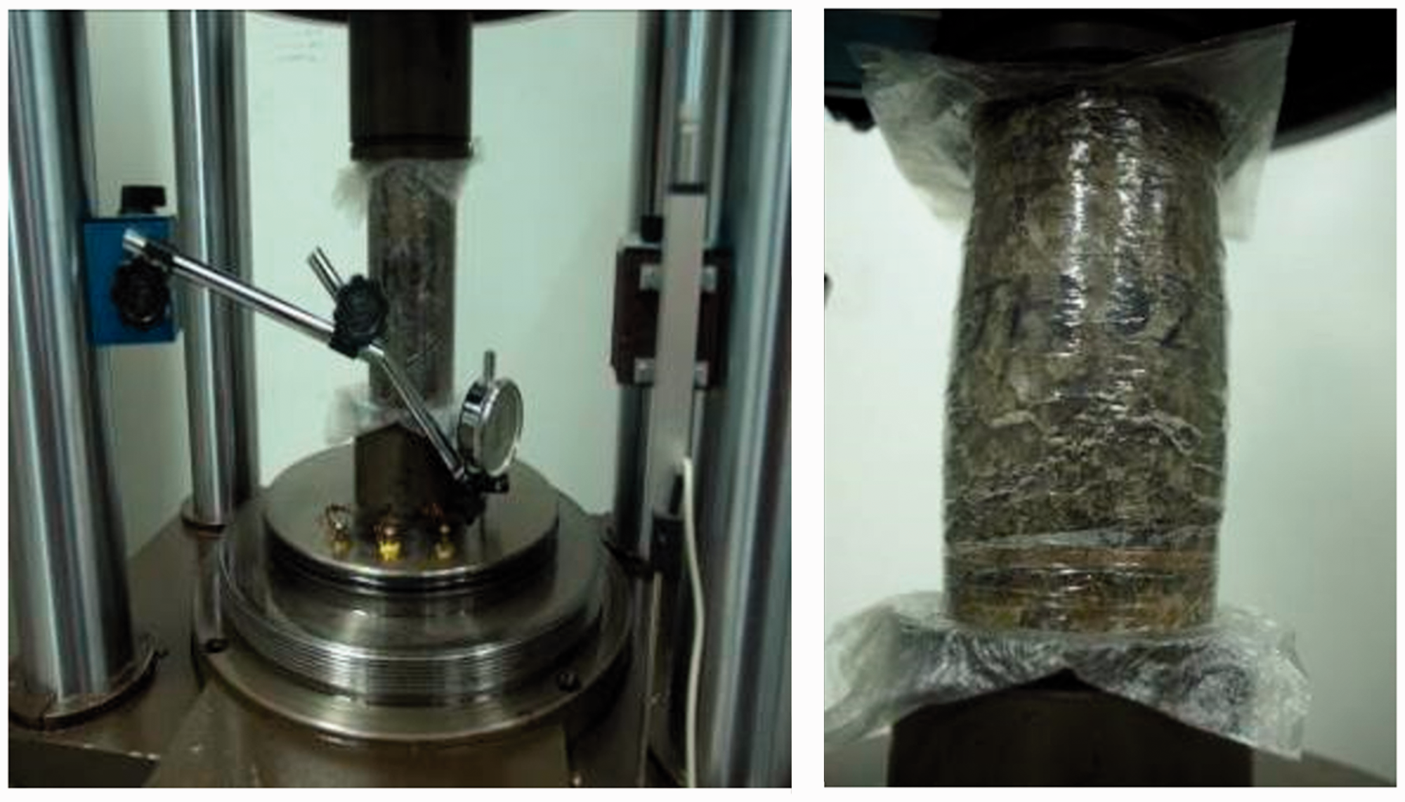
Experimental results
This creep test was divided into 10 stages subjected to increasing loadings, lasting about half a year. Figure 5 shows creep curves under step loading. It can be seen that creep deformations in the first seven stages are not significant, and stabilized as time continued. However, in the last stage, the creep shows accelerating phenomenon with obvious nonlinear characteristics.
Creep curves under step loading.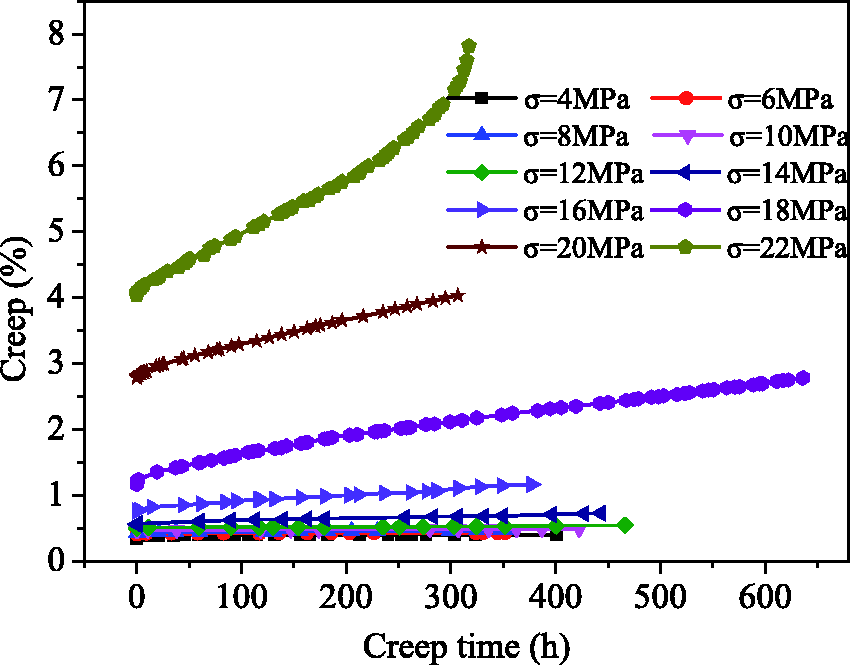
Model verification
Equation (7) presents the constitutive equation of the nonlinear creep damage model; however, the damage evolution equation and steady-state creep rate function are not presented. Therefore, to verify the accuracy of this model, a set of damage evolution equations and steady-state creep rate functions are presented in the following equations. Zhou et al. (2013) and Kang et al. (2015) assumed the damage evolution of salt rock in the rheological process as a negative exponential function. The same assumption has been applied here as well.

Substituting equation (8) into equation (2), one can get

The Norton power law is commonly used to model the creep behavior of salt rocks. The standard form of this law is

Under uniaxial compression, equation (10) could be simplified as

Replacing equation (9) by equation (11), one can find

Substituting equation (9) into equation (3), we obtain

Substituting equation (12) into equation (6), we get

Several constitutive models describing the characteristics of decelerating creep and steady creep have already been proposed, and so these would not be discussed in depth in this paper. The fractional Maxwell model is employed herein (Wu et al., 2015).

Substituting equations (13) and (14) into equation (7), one can obtain

Correlating equations (15) and (16), we have
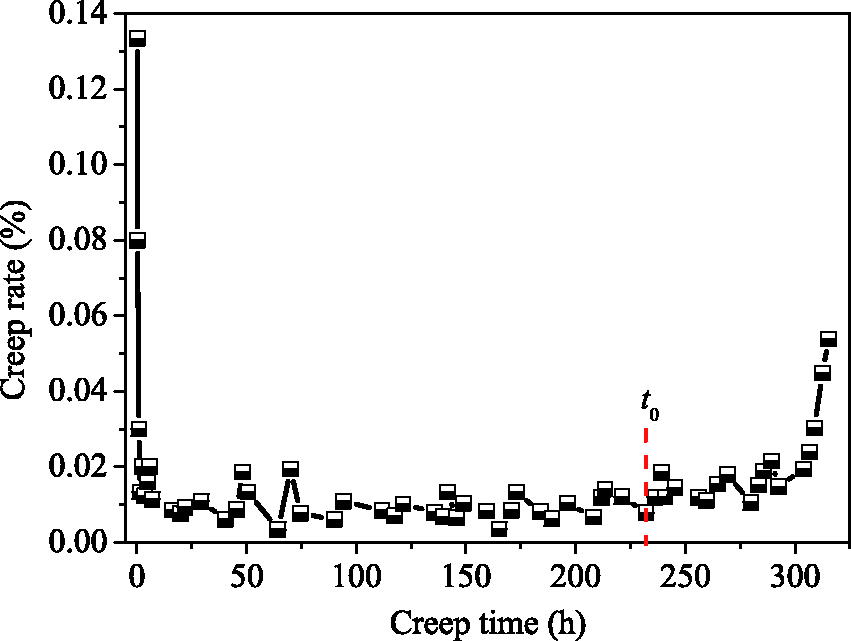
The present creep test results show that the accelerating creep phenomenon emerges in 10th stage of creep. The accelerating creep curve is shown in Figure 6. Beyond the steady creep stage, it can be seen from Figure 6 that the creep curve begins to rise rapidly at time t0, which is defined as the initial point of accelerating creep stage. Based on Figure 6, the creep rate curve is plotted (Figure 7), which shows that the creep rate gradually augments from time t0, thus confirming that time t0 is the initial point of accelerating creep.
Creep curve (σ = 22 MPa). Curve of creep rate (σ = 22 MPa).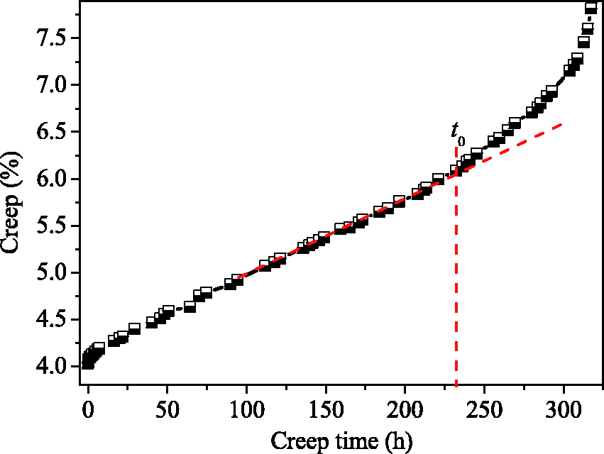
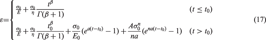
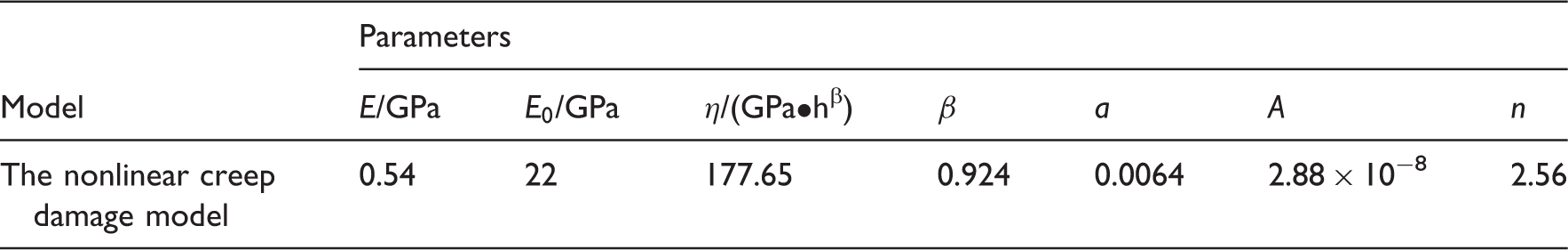
Concerning creep test results in the 10th stage, a nonlinear creep damage model was used to fit them, where σ0 = 22 MPa. According to equation (17), the nonlinear least square method is applied to analyze these test data. A comparison of fitting results and test data is shown in Figure 8, with Table 1 listing the parameters determined by fitting analysis.
Creep curves of salt rock and the model proposed. Parameters determined by fitting analysis based on creep tests of salt rock.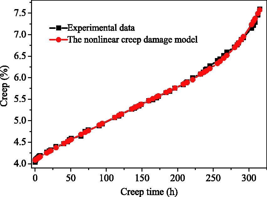
The fractional Maxwell model could favorably describe the initial and steady creep stages (see Figure 8); moreover, it better reflects the nonlinear gradual deformation of the initial creep stage. The proposed nonlinear creep damage model fits well to these test data from the accelerating creep stage while also represents the characteristics of nonlinear accelerating creep. Therefore, in this work, the accelerating creep stage is assumed to be a coupling process of loading and creep. The total strain equaling the sum of loading strain and creep rate is thus correct; besides, this confirms that the proposed nonlinear creep damage constitutive model is reasonable. Damages appearing in the accelerating creep stage of salt rock would increase stress. This stress increase not only generates loading strain but also becomes steady as the creep rate rises. This coupling explains why salt rocks present nonlinear accelerating characteristics during the accelerating creep stage. To some extent, in addition to considering the actual creep process, the proposed nonlinear creep damage model also can satisfactorily predict test data.
Discussion
In this work, model parameters were determined based on the nonlinear least square method, which are not unique, but reasonable. These parameters are explained in depth in the following sections.
In the aforementioned parameter estimation method, minimizing the quadratic sum of the errors is used as the judgment criterion to estimate the nonlinear static model parameters. Therefore, the parameters determined using this method, in theory, are not unique. Thus, the rationality of the parameters should be verified. In this model, E0 is the elastic modulus of the samples in traditional tests, which is obtained through traditional uniaxial compression test; E is the equivalent elastic modulus of rock in the creep tests. The equation Comparison of the theoretical results and experimental results.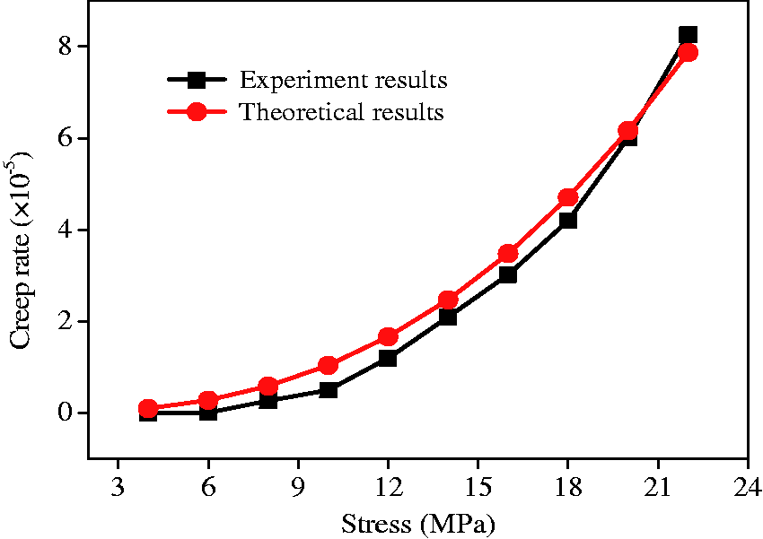
In the proposed creep model, η is the viscosity coefficient and β is the fractional order. In general, β is below 1 and approximates 1 for the creep curves at the accelerating stage. Therefore, β = 0.924 is proper. Let 
It can be seen from Figure 9 that when
In the proposed creep model, a is the damage index. The damage evolution curves (Figure 10) can be plotted according to equation (8).
Damage evolution curves at the accelerating creep stage.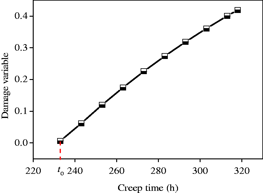
The damage at the creep failure is about 0.4 (see Figure 10). Because the increase in damage leads to not only the increase in the creep rate but also the increase in the effective stress, the damage at the creep failure is not too big (generally below 0.5). Therefore, “a” is reasonable.
Thus, all the parameters determined by the nonlinear least square method are reasonable.
Besides, because the accelerating creep stage is assumed to be a coupling process of loading and creep, we propose that the total strain equals the sum of loading strain and creep rate, and derive a new nonlinear creep damage model. Nevertheless, the damage evolution equation and steady creep rate function are not presented in equation (7). To verify the model, a set of damage evolution equations and steady creep rate function are given. It is generally accepted that the steady creep rate is described by exponential function, but the damage evolution equation remains to be solved. Thus, we suggest using advanced testing equipment to monitor the damage evolution of internal rock; if necessary, damage can be even redefined to arrive at a more accurate damage evolution equation, to verify the proposed nonlinear creep damage model.
Conclusion
In this paper, a new nonlinear creep damage model for salt rock was established and verified. The primary conclusions of the study are as follows:
Because of damages generated inside rocks in the accelerating creep stage, the stress increases gradually. However, creep is defined by assuming constant stress with strain increasing over time. Thus, the accelerating creep no longer represents the conventional creep process.
The total strain is proposed to be equal to the sum of loading strain and creep rate based on the understanding that the accelerating creep stage is a coupling process of loading and creep. A new nonlinear creep damage equation is derived according to this assumption.
Damages occurring in the accelerating creep stage for salt rock increase the stress. This not only generates loading strain but also causes the steady creep rate to increase. This coupling explains why salt rocks present nonlinear accelerating characteristics in the accelerating creep stage.
The proposed nonlinear creep damage model is used to fit salt rock test data. Obtained results show that this model fits well to these test data, and also favorably represents the nonlinear characteristics of accelerating creep, thus validating our model.
Footnotes
Acknowledgements
The authors are grateful to the anonymous reviewers for their helpful comments which have improved the presentation of this paper significantly.
Declaration of conflicting interests
The author(s) declared no potential conflicts of interest with respect to the research, authorship, and/or publication of this article.
Funding
The author(s) disclosed receipt of the following financial support for the research, authorship, and/or publication of this article: This work is supported by National Natural Science Foundation of China (no. 51704044, 51604044), General Projects of Basic Science and Frontier Technology Research Projects of Chongqing Science and Technology Planning Project (no. cstc2017jcyjAX0264), Fundamental Research Funds for the Central Universities (106112017CDJXY240001), and Open Fund of State Key Laboratory of Water Resource Protection and Utilization in Coal Mining (no. SHJT-16-30.4).