
Abstract
Precast concrete frame structures are widely adopted around the world due to their various advantages, so it is important to study their seismic performance. The development of damage mechanics has enabled us to accurately investigate the typical failure mechanisms of precast structures. This paper presents three of the most commonly used modeling approaches based on damage mechanics for analysis of precast reinforced concrete structures under cyclic loading and compares the performance of the three models. Particularly, the shear behavior of the joint panel and the bond-slip behavior of the beam–column interfaces are especially considered, which are the key issues for precast concrete structures. First, the fundamental assumptions, formulations, and modeling strategies are given in detail for each approach. Then, the unified damage mechanics for concrete is introduced, and the model for reinforcement bars and the consideration of the bond-slip effect are also presented. Several benchmark cyclic tests of precast beam-to-column connections are chosen to evaluate the accuracy and efficiency of the modeling approaches. The numerical results, e.g. the capacities, deformations, and energy dissipation of the connections, are compared to the experimental results to show the ability of each approach. With this study, we can gain a further understanding of the characteristics and applicability of each modeling approach, helping us make a better decision in choosing which modeling approach is appropriate.
Keywords
Introduction
Precast concrete structures are widely used around the world, as these structures provide various advantages over the traditional cast-in-situ concrete structures, such as fast construction, less manual labor, and low pollution. However, there are also concerns that their seismic resistance is not as good as that of the cast-in-situ structures due to the weak integrity, especially at the beam-to-column connections that connect different precast components. Consequently, it is of great importance to study the mechanical behavior of the connections since they are the most different part between precast and traditional concrete structures.
To this end, experimental investigations were first performed, as they are the most physically meaningful method. The designed precast beam-to-column connections were tested by subjecting them to lateral cyclic loading to determine whether the specimens had similar capacity, ductility, and energy dissipation as their monolithic counterparts or to find failure mechanisms and the weakest part of the connections (see Alcocer et al., 2002; Bull and Park, 1986; Chen et al., 2012; Guan et al., 2016; Im et al., 2013; Xue and Yang, 2010). There also exist a few tests on entire precast building structures to study the global behaviors (see Brunesi et al., 2015a; Dal Lago et al., 2018). Although these experiments can obtain realistic results, they are usually both cost and time consuming. Moreover, the influencing parameters can hardly be fully investigated since we have very limited resources in terms of testing facilities.
To overcome the abovementioned drawbacks arising from the experimental studies, several numerical models were also developed for analysis of precast structures. In general, there are three major families of models, i.e. the 3D solid element-based models (Bahrami et al., 2017; Hawileh et al., 2010; Kaya and Arslan, 2009; Kulkarni et al., 2008), the 1D beam element-based models (Brunesi and Nascimbene, 2014; Feng et al., 2016, 2019b; Li et al., 2011; Valipour and Foster, 2010), and the macro-level joint element-based models (Altoontash, 2004; Bao et al., 2008; Feng et al., 2018c; Yu and Tan, 2014). The first one among the three is the most elaborate family, in which the models capture both global and local responses of the connection, such as concrete crushing and reinforcement fracturing. Especially, some typical features in precast system can also be reflected, e.g. surface-to-surface contact between the beam and column faces, etc. (see previous works by Hawileh et al., 2010; Kaya and Arslan, 2009). However, the computational burden is very high since the total number of degrees of freedom is very large. Meanwhile, one may also face the problems of convergence (implicit solver) or stability (explicit solver) while using such an approach. In contrast, the second family, i.e. the 1D beam element-based models, adopts fiber beam elements to simulate the beam/column components, thus greatly reducing the total degrees of freedom. Nevertheless, only structural and section level responses can be obtained, while the responses of more detailed regions cannot be attained. Moreover, two typical effects for the connection of precast structures, i.e. shear of the panel and bond-slip of the interfaces, are ignored since an Euler–Bernoulli type beam element is usually employed. The third family of models is established on the basis of the second one, while adding additional macro-level joint elements to represent the shear and bond-slip behaviors of the connection. With this modification, the accurate behavior of the connection can be well captured, but these models are still restricted to the structural and section levels. The problem lies in the calibration of the parameters, which usually have no physical sense and need to be determined by experience.
One common problem with the abovementioned modeling approaches is the choice of material models, especially for concrete, as its mechanical properties are rather complex. Currently, several options can be followed to model concrete behavior, e.g. smeared-crack models and damage mechanics-based models. Smeared-crack models (Bentz et al., 2006; Hsu, 1988; Hsu and Zhu, 2002; Lotfi and Shing, 1991; Maekawa et al., 2003; Rots and Blaauwendraad, 1989; Vecchio and Collins, 1986) assume that the cracks are smeared over the whole element and adopt two empirical stress–strain relations for concrete behavior in the two principal directions. The advantage is the simplicity, but the phenomenological nature limits the application of these models in large scale problems since they involve several empirical parameters and the definition of the loading paths is rather complicated. On the other hand, damage mechanics-based models (Faria et al., 1998; Ju, 1989; Lee and Fenves, 1998; Ren and Li, 2013; Ren et al., 2015; Tesser et al., 2011; Wu et al., 2006) use a general variable, say, damage, to represent the degradation of the material behavior and then adopt the thermodynamics to establish the constitutive model, damage evolution, and plasticity evolution. With this solid theoretical foundation, damage and plasticity are combined in one system, making damage models a standard tool for finite element simulation of concrete structures.
Obviously, integrating damage models and finite element methods enables us to perform comprehensive numerical simulations of precast concrete structures. However, it is also well recognized that different modeling approaches (i.e. 3D solid element-based, 1D beam element-based, and macro-level element-based) have different assumptions and simplifications, and thus, the numerical responses are strongly model-dependent. Although there are several comparative studies that have been done to demonstrate the applicability of these approaches, they focus more on traditional concrete structures, which were cast-in-place. Precast concrete structures, on the other hand, have their own characteristics. The postcast region of the connections is the critical region, as the performance shown by postcast concrete is very hard to guarantee. As a consequence, the shear behavior of these critical regions and rebar slippages will be very significant, which are usually ignored for cast-in-situ concrete structures. In this regard, this paper presents three new numerical models for precast concrete structures to resolve the above issues and compare the applicability of these models by simulating two typical precast concrete structures. This work may offer a better understanding of the features of different modeling approaches and guidelines for seismic analysis of precast concrete structures.
Proposed modeling approaches for precast concrete structures
As discussed before, precast concrete beam-to-column connections have significant shear behavior and bond-slip effects, and thus, three new approaches are proposed. The fundamentals, assumptions, and modeling strategies are introduced herein.
Three-dimensional solid element-based approach
The first modeling approach is based on a continuum 3D solid element, which is performed on the platform of the famous finite element package ABAQUS. Note that there are also several works using ANASYS to perform the cyclic analysis of RC structures, e.g. Hawileh et al. (2011) and Sakar et al. (2014), which can obtain excellent results as well. We use ABAQUS since it provides user-subroutines for us to implement our own models. The concrete components, i.e. the precast beam or column units as well as the postcast regions, are modeled with the eight-node solid element C3D8R. Meanwhile, the two-node truss element T2D2 is chosen to simulate the reinforcement bars. The reinforcement bars are embedded into the concrete matrix to ensure a perfect connection between them. The bond-slip effect at the critical region is implicitly considered by modifying the stress–strain relations of the reinforcement according to the derived slippage of the bars. The mesh size for the finite element model is set as 50 mm × 50 mm × 50 mm after a fracture energy-based mesh convergence study considering both the numerical accuracy and the computational efficiency. Moreover, to reflect the properties of the interface between the pre- and postcast concrete, a thick layer is placed between the pre- and postcast components. According to our previous engineering practice (we used to measure the thickness in some precast specimens), the thickness of the layer is set as 10 mm. Figure 1 shows the modeling strategy (Feng et al., 2018b). Note that in this study, we did not consider pre-stressed precast concrete specimens, which requires modeling of pre-tensioning of the steel tendons. This can be achieved by using initial stress condition method as done by Wu et al. (2018) in software ABAQUS or by using the pre-tension element method as done by Hawileh et al. (2010) in software ANASYS.
The 3D solid element-based model for the precast beam-to-column connection.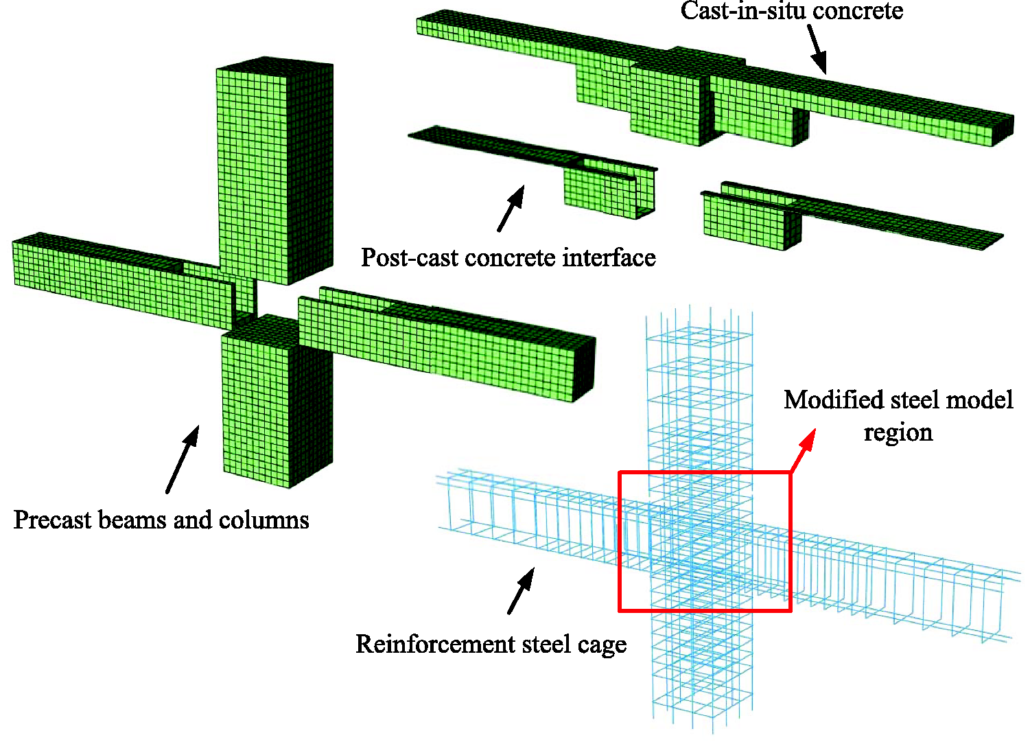
The damage-plasticity model is used for concrete, and the strength of the concrete for the interface layer is reduced to
Enhanced fiber beam element-based approach
The second modeling approach is based on an enhanced displacement-based fiber beam element and falls under the Timoshenko beam theory that directly takes the shear deformation into consideration (Feng et al., 2017; Feng and Xu, 2018). The element is developed by the author and is implemented in ABAQUS. The fiber model divides the section into concrete fibers and reinforcement steel fibers and assumes that shear deformation is resisted only by the concrete fibers and is uniformly distributed across the whole section. Consequently, when the steel fibers are in a uniaxial stress state, the concrete fibers are in a multiaxial stress state. In this regard, the normal shear interaction can be directly reflected at the material level by using a multiaxial damage plastic model for the concrete fibers. It should be noted that a condensation procedure is also required to satisfy the transverse equilibrium of the concrete fibers, see Figure 2 (Feng and Xu, 2018). Meanwhile, similar to the first approach, for elements at the critical regions, the bond-slip effect is considered by using the modified M–P model for reinforcement fibers.
Fiber section representation for the Timoshenko element.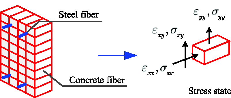
A schematic representation of this modeling strategy is given in Figure 3, in which the rigid link element is adopted to represent the joint panel region. The elements in red use the modified M–P model to reflect the bond-slip effect, while the other elements use the general M–P model. The element mesh size is determined by the plastic hinge length Lp to overcome the localization issues, which is calculated according to the following empirical formula (Bae and Bayrak, 2008)
Enhanced fiber beam element-based model for the precast beam-to-column connection. M–P: Menegotto–Pinto.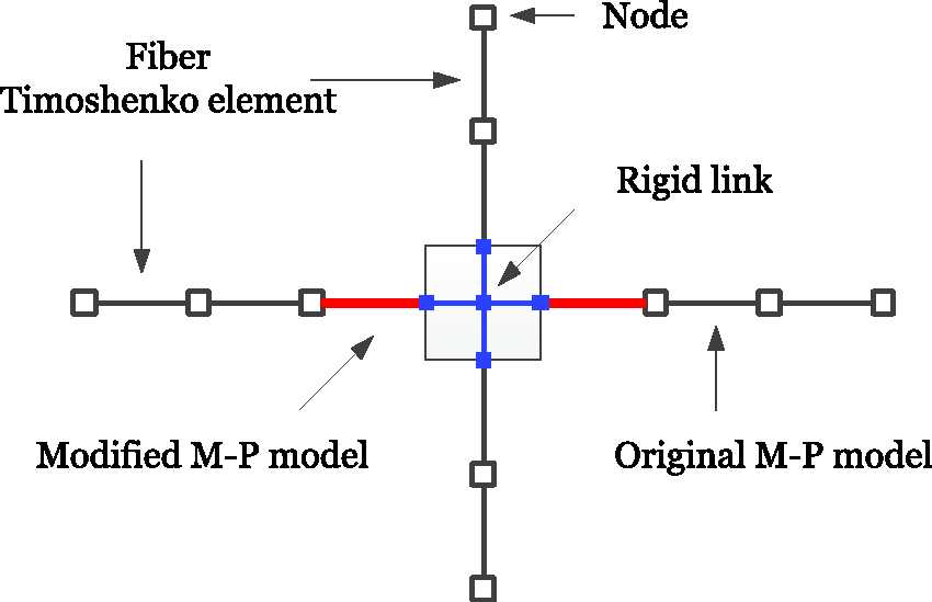

Macro-level joint element-based approach
The third modeling approach is based on a macro-level joint element. The beam/column members are modeled with the regular fiber beam element, i.e. an Euler–Bernoulli type, while the beam-to-column joint is modeled with the Joint2D element developed by Altoontash (2004). This approach is performed using the finite element software OpenSEES, and the schematic diagram is shown in Figure 4.
Macro-level joint element-based model for the precast beam-to-column connection.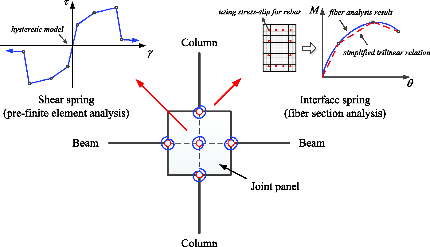
For regular fiber beam elements, concrete fibers are simulated with the uniaxial version of the damage model, while steel fibers are simulated with the M–P model. For the Joint2D element, as can be seen, the element has five components, i.e. one shear spring representing the panel’s shear behavior and four interface springs representing the moment-rotation behavior considering the bond-slip effect. Parameter calibration of the spring properties is the main concern of this approach. For the shear spring, we need to perform a pre-finite element analysis of the joint panel to obtain the skeleton of the shear stress–strain curve, and the cyclic behaviors are then defined by the hysteretic model in OpenSEES. For the interface springs, we also need to use a unit-length fiber sectional analysis of the section at the beam ends to get the moment-rotation behavior of the section, in which the stress–strain relation is replaced by the stress–slip relation (will be given in the following sections) for reflecting bond-slip. Then we use a tri-linear model (hysteretic model) to approximate the moment-rotation behavior and assign this simplified model to the springs.
Damage mechanics-based concrete model
Damage model
To accurately reflect the behavior of concrete, the damage mechanics-based model is adopted. Numerical problems are avoided by the use of the model, which is established in the effective stress space. Therefore, starting from the strain equivalent principle (Lemaitre, 1971), the effective stress

The properties of concrete under tension and compression are not the same, and thus, the effective stress can be further divided into a tensile (positive) part and a compressive (negative) part, i.e. (Faria et al., 1998; Ju, 1989; Wu et al., 2006)


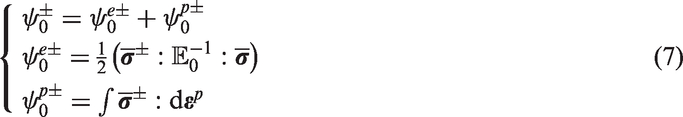
Based on the above effective stress decomposition, we introduce two damage variables reflecting tensile and compressive damages and further employ the Helmholtz free energy (HFE) ψ as follows (Wu et al., 2006)

Calling on the Clausius–Duhem inequality


Obviously, we now need the plasticity and damage evolution to complete the model. For the first one, i.e. the definition of the plastic strain, the evolution is based on an empirical plastic model (Faria et al., 1998; Tesser et al., 2011)


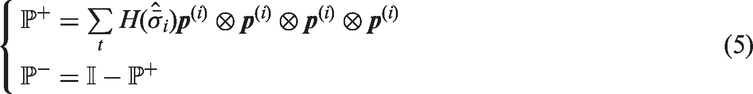
For the second one, i.e. the damage evolution, it can be found that the damage tensor includes a negative part D– and a positive part D+, showing the tensile and compressive damages of concrete, respectively. That is

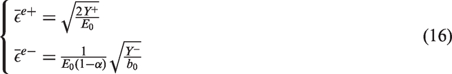
The evolution of the damage variables is restricted by the damage energy release rates

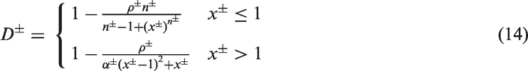
The detailed damage evolution function is achieved through an empirical expression fitted to experimental data, i.e. (Feng and Li, 2015)

The typical stress–strain curve obtained from the above model can be seen in Figure 5.
Typical stress–strain curve obtained from the model.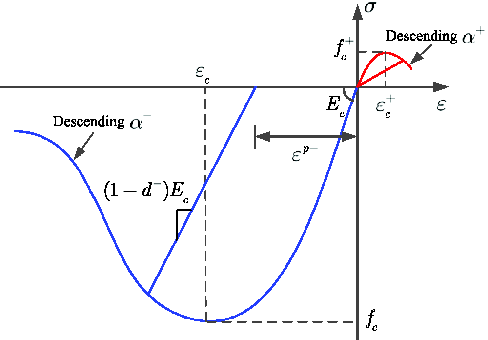
Concrete–reinforcement interaction
Moreover, to enhance the shear behavior of the model to analyze the reinforced concrete (RC) structures, we need to further modify the damage evolution of the model. When RC is subjected to a shear force, it is in the compression-tension stress state. Thus, two features should be accounted for to accurately reflect the shear behavior, i.e. tension stiffening (TS) and compression softening (CS), as shown in Figure 6. TS can be included in the model by changing the positive damage function to
TS and CS of RC.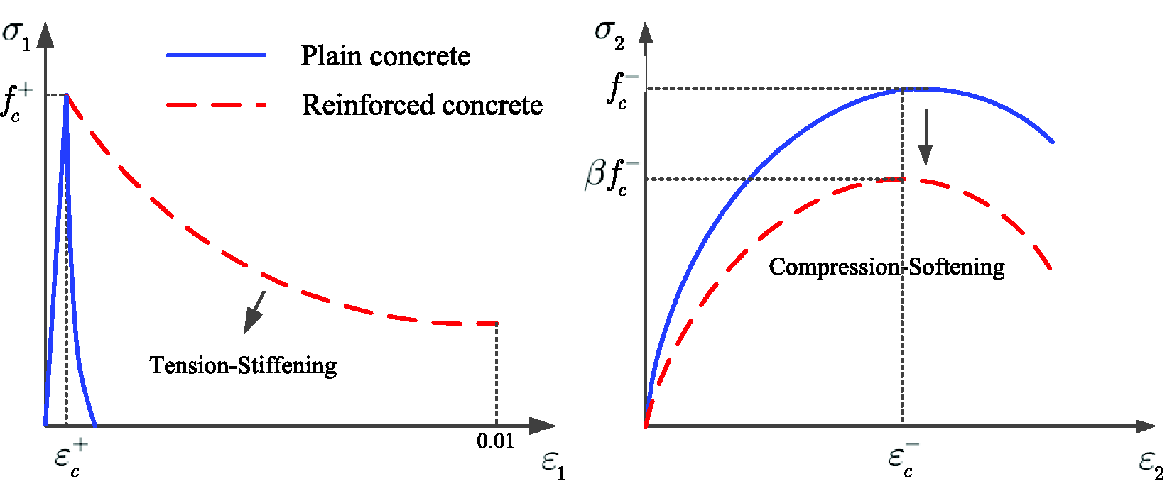

For the compression-softening effect, the principal compressive behaviors are coupled with the principal tensile behaviors. Thus, the negative damage variable is reconstructed as (Feng et al., 2018a)

Reinforcement model and bond-slip effect
Reinforcement
The reinforcement material adopts the famous M–P model (Menegotto, 1973), which defines the uniaxial stress–strain relation shown in Figure 7. The monotonic behavior is described by a bilinear relation
M–P model for reinforcement steel.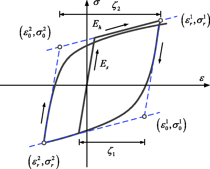


Bond-slip effect
The bond-slip effect is a key factor for the simulation of precast concrete structures (Feng et al., 2019a). It can be considered in two different ways for the abovementioned three modeling approaches. The first way is to include the slippage in the stress–stress model (Feng et al., 2018b; Feng and Xu, 2018), which is an implicit method and is used in both the 3D solid element-based approach and the enhanced fiber beam element-based approach. The reinforcement total strain
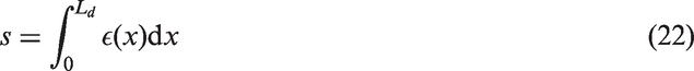
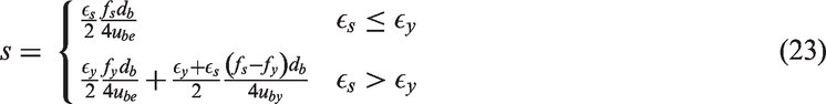
It is easy to find that both methods require the stress–slip relation of the bars, which can be obtained by either experiments or analytical derivations. In this paper, an analytical model is adopted. The slip s is derived based on a stepped bond stress field assumption, as shown in Figure 8, where the bond stresses in the elastic and plastic regions of the reinforcement are considered as constant, and thus, the total slip can be expressed by the following equation according to the equilibrium condition (Feng et al., 2018b)
Stepped bond stress field assumption for bars at the critical region.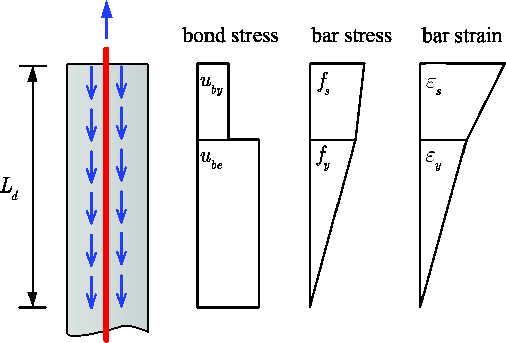
Selected cyclic tests of precast beam-to-column connections
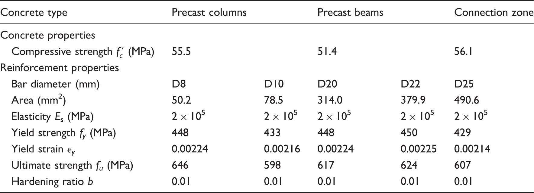
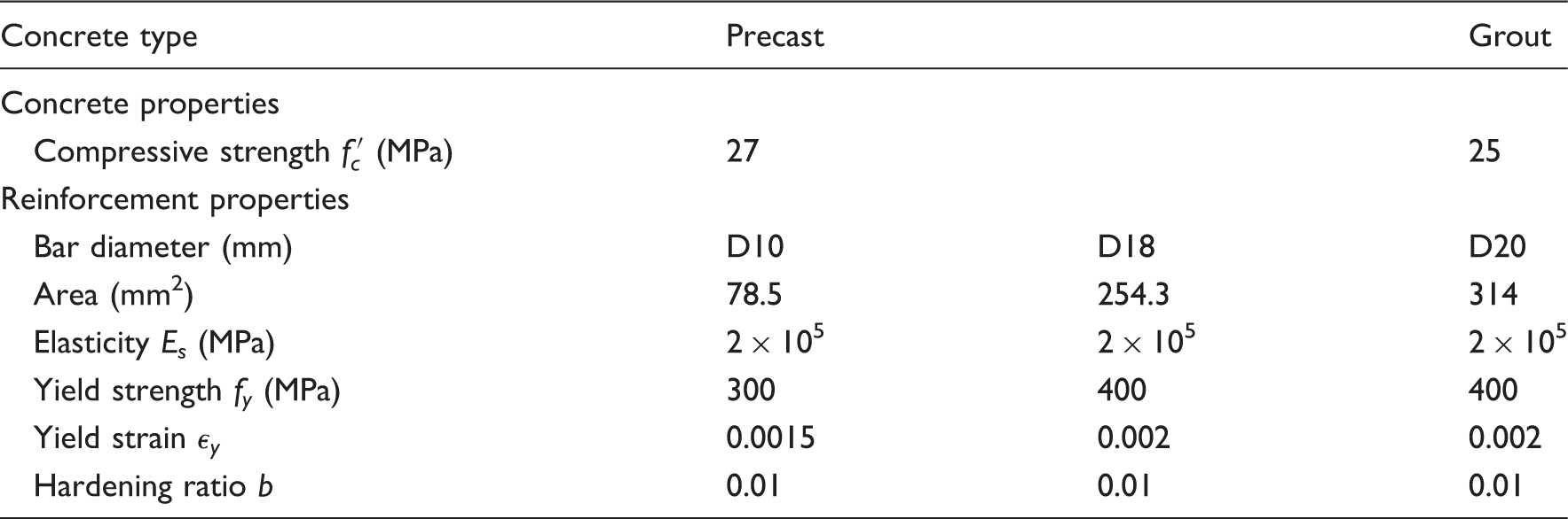
Two typical precast beam-to-column connections, which were tested under cyclic loading, are chosen as examples to study the reliability and applicability of the different modeling approaches. One of the specimens is an interior connection (specimen S2), while the other one is an exterior connection (specimen BCT3). The configuration of the connections is shown in Figure 9. The specimen dimensions and reinforcing details are all given in the figure. Tables 1 and 2 show the material properties of the concrete and reinforcement bars used in the specimens. More details about the specimen information and experimental setup are shown in Guan et al. (2016) and Parastesh et al. (2014). Two stages are applied in the loading scheme, i.e. first, an axial load is applied on the top of the column through force control, and then, a lateral cyclic load is imposed at the same position via displacement control.
Configuration of the beam-to-column connections. (a) Interior connection and (b) exterior connection. Material properties of the interior beam-to-column connection specimen. Material properties of the exterior beam-to-column connection specimen.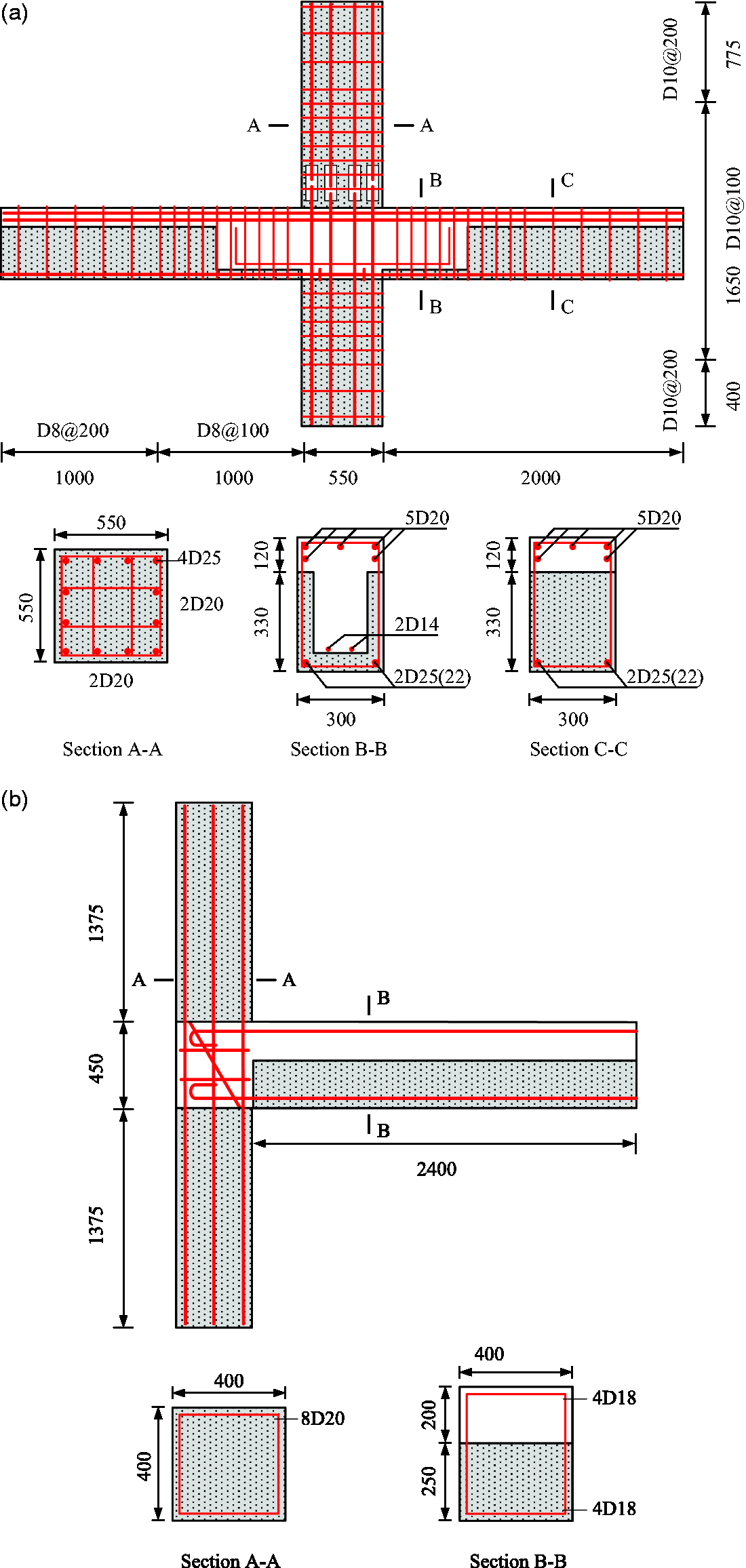
Analysis results and discussion
Interior beam-to-column connection
First, the numerical results of the interior beam-to-column connection obtained using the three modeling approaches and their comparisons with experimental data are discussed here. Note that all the parameters are set according to the test values given in Table 1. The modified strength and stiffness for reinforcement incorporating bond-slip are 360 and 160,000 MPa, respectively; the parameters (shear strain–stress) for the shear spring are
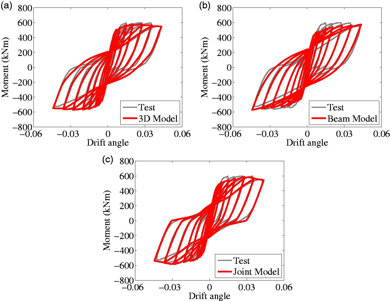
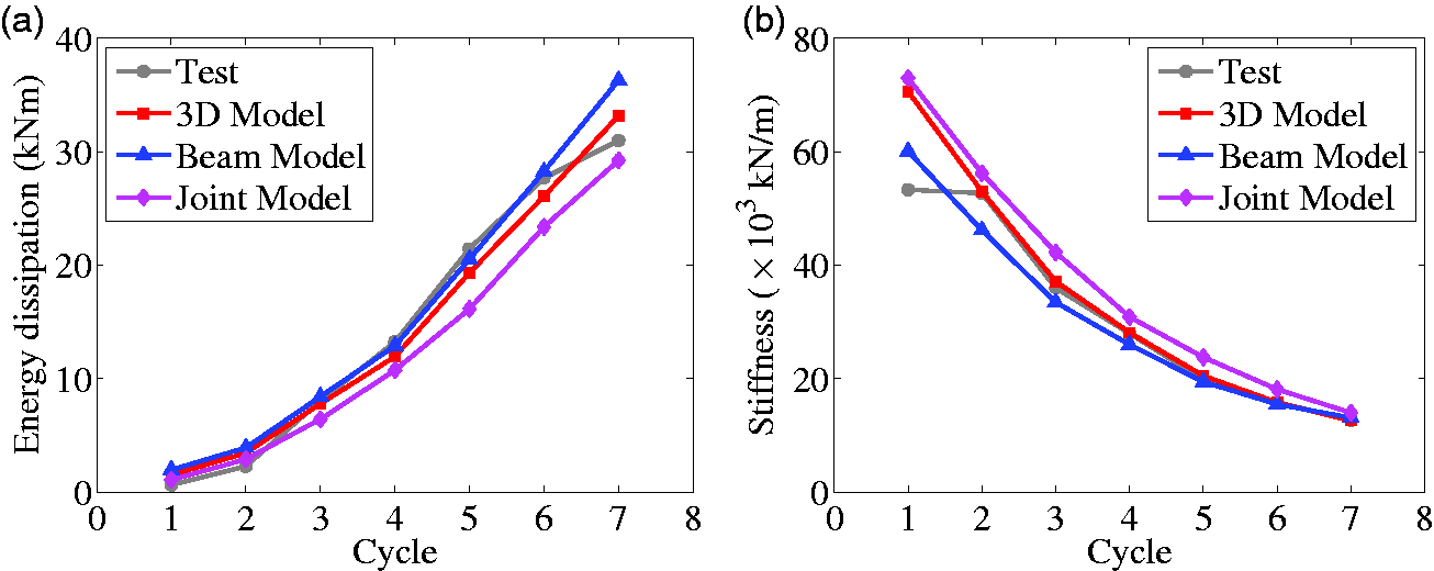
The deformed shapes of the specimen from the three modeling approaches are shown in Figure 10, which have the same trend, indicating that the three approaches have similar capacities in capturing the final deformation of the specimen. Meanwhile, the cyclic bending moment-drift angle curves obtained by the three models are shown in Figure 11. It can be seen from the figure that, in general, the three approaches can all obtain reasonable results for the connection. The force capacity, stiffness degradation, and energy dissipation are all well reproduced. The peak capacity obtained by the experiment is 588 kNm, while those obtained by numerical models are 577 kNm (3D element-based), 576 kNm (beam element-based), and 586 kNm (joint element-based), differing by 1.8, 2, and 0.3%, respectively. Meanwhile, the numerical results match the experimental results very well in terms of the energy dissipation and stiffness degradation, as Figure 12 shows. Here Figure 12(a) shows the cumulative energy dissipation of each cycle and Figure 12(b) shows the stiffness degradation of each cycle. Note that original tests imposed three cycles for each drift angle level, but we only modeled the first cycle of each drift angle level as the low-cycle fatigue cannot be considered in the material models. Obviously, there also exist several differences between the three models. The capacity at the yielding stage is slightly underestimated by the beam element-based and joint element-based models, as the concrete stress state is greatly simplified in these two approaches. The pinching effect is reflected by the joint element-based model much better than the other two approaches. This result may be caused by the shear behavior of the panel being separately represented by a shear spring in the joint model, and thus, the behavior can be controlled much better by choosing the appropriate spring parameters.
Deformed shape of the interior connection (amplitude factor: 5). (a) 3D model, (b) beam model, and (c) joint model. Cyclic behavior of the interior beam-to-column connection. (a) 3D model, (b) beam model, and (c) joint model. Features of the cyclic curves for the interior connection. (a) Cumulative energy dissipation and (b) stiffness degradation.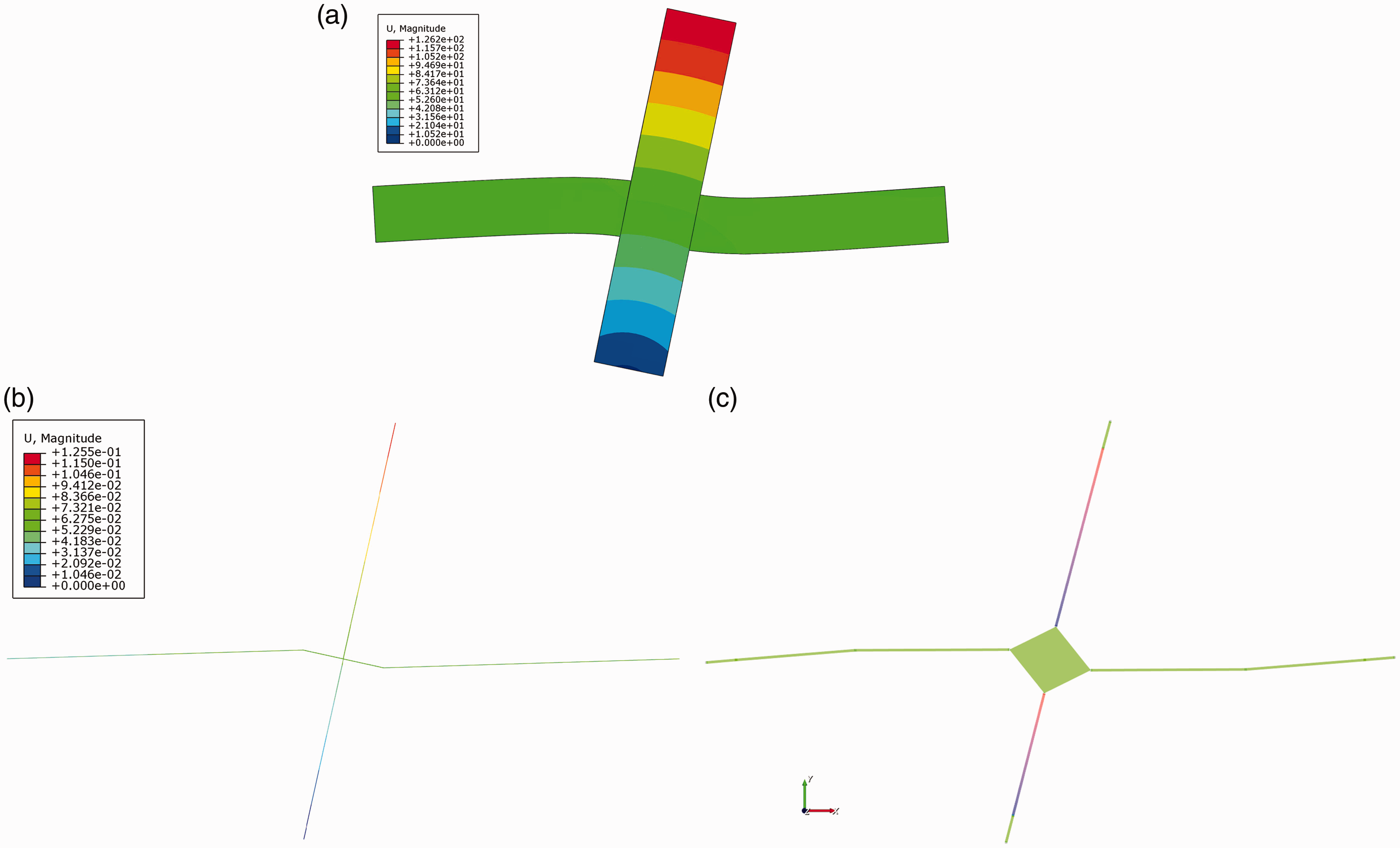
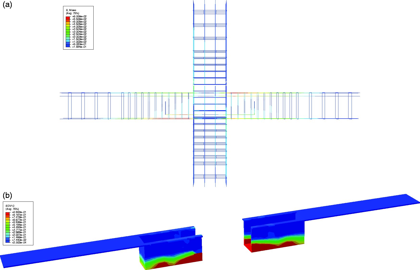
On the other hand, the 3D model can also obtain the detailed damage distribution of the specimen, as shown in Figure 13. The obtained concrete crushing regions (failure mode) are very similar to that observed in the experiment. Meanwhile, some further detailed local responses can also be attained, as shown in Figure 14, which gives the stress state of the reinforcement cage and the damage pattern of the pre- and postcast concrete layer, helping us further understand the force transfer mechanism of the beam-to-column connection. Unfortunately, this failure mode and detailed responses cannot be achieved by the other two models. However, the computation efficiencies of the beam element-based and joint element-based models are much greater than that of the 3D element-based model. On a computer with 8 GB of RAM and an i7-2.40 GHz CPU, the computational time is 98 s for the beam element-based model and 55 s for the joint element-based model, while that for the 3D element-based model is more than 4 h.
Experimental and numerical failure modes of the interior beam-to-column connection. (a) Experimental and (b) numerical. Detailed response of the interior connection. (a) Reinforcement stresses and (b) damage of the interface layer.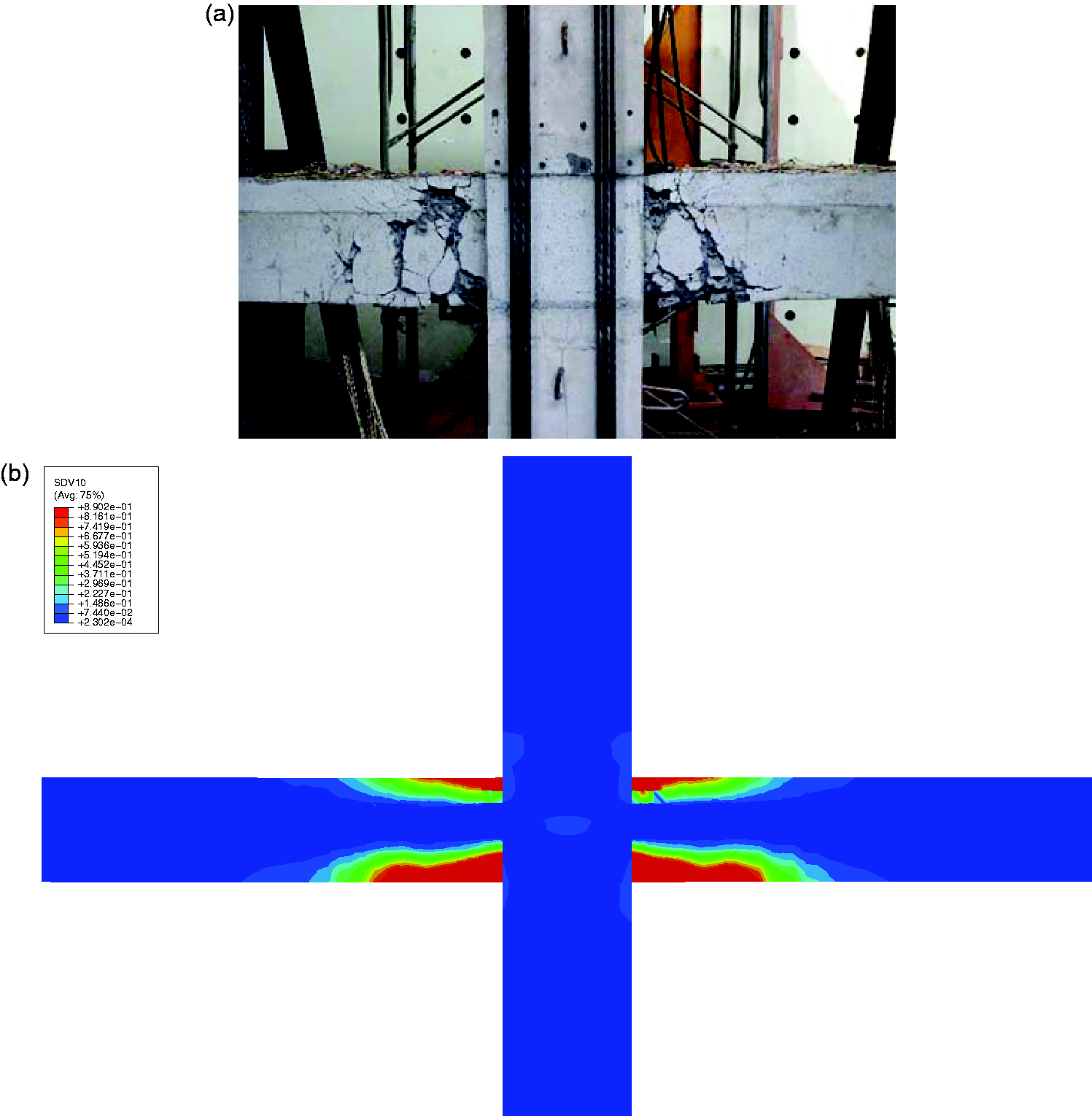
Exterior beam-to-column connection
The numerical results for the exterior beam-to-column connection are discussed in this part. Similarly, the parameters are set according to the test values given in Table 2. The modified strength and stiffness for reinforcement incorporating bond-slip are 300 and 176,000 MPa, respectively; the parameters (shear strain–stress) for the shear spring are
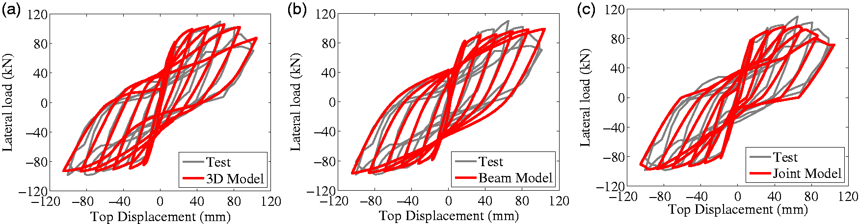
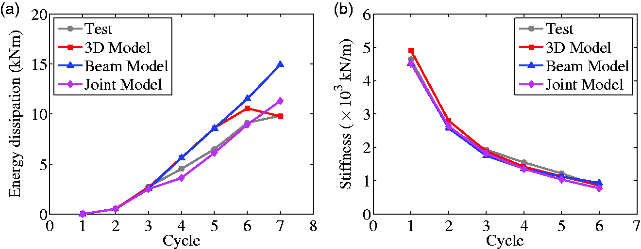
First, the deformed shapes from the three models are demonstrated in Figure 15. Evidently, they are very close to each other, indicating that the three modeling approaches are all accurate in the deformation prediction. Then, the cyclic lateral load–top displacement curves are shown in Figure 16. Again, good agreement is achieved for all the three modeling approaches. Similar to the interior connection, the pinching effect is better reproduced by the 3D element-based model and joint element-based model since they focus more on the joint panel region. The simulated peak capacities are 106, 98, and 97 kN for the 3D element-based model, beam element-based model, and joint element-based model, respectively, while the experimental result is 109 kN. The energy dissipation and stiffness degradation are also well captured, as shown in Figure 17.
Deformed shape of the exterior connection (amplitude factor: 5). (a) 3D model, (b) beam model, and (c) joint model. Cyclic behavior of the exterior beam-to-column connection. (a) 3D model, (b) beam model, and (c) joint model. Features of the cyclic curves for the exterior connection. (a) Cumulative energy dissipation and (b) stiffness degradation.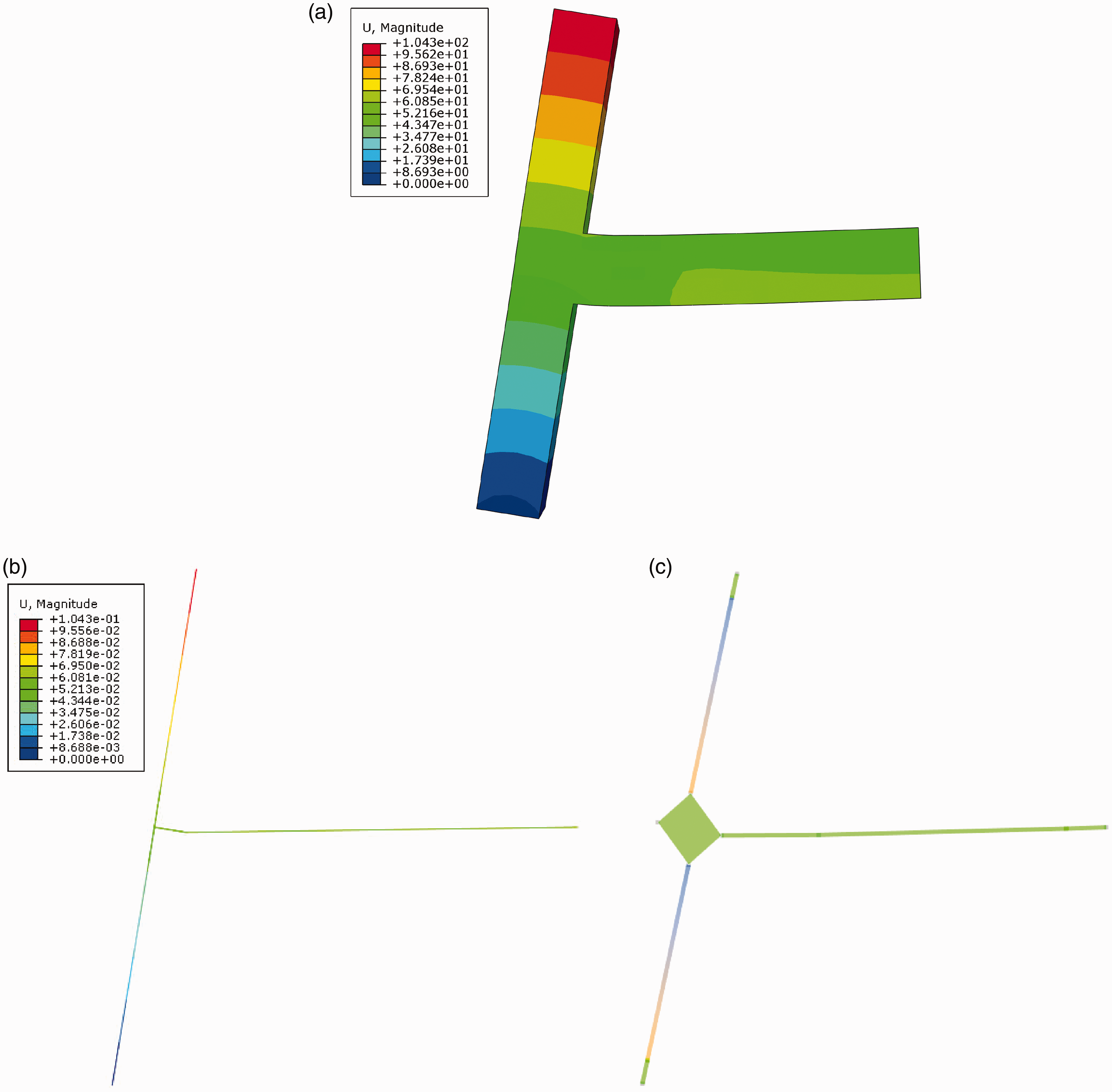
In addition, the failure mode obtained by the 3D element-based model is shown in Figure 18, representing plastic hinge occurring at the beam end, which is in accordance with the experimental findings. However, once again, the computational time for the 3D element-based model is approximately 3 h, much more than those of the beam element-based and joint element-based models, which are both less than 1 min.
Experimental and numerical failure modes of the exterior beam-to-column connection. (a) Experimental and (b) numerical.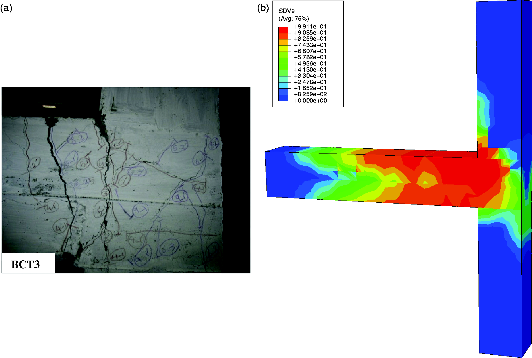
Summary and conclusions
In this paper, a comprehensive comparative study is conducted to investigate the applicability of different modeling approaches for seismic analysis of precast concrete structures. The models all adopt a damage model to simulate the behavior of the concrete material, and the modeling assumptions and strategies are all presented in detail. Two benchmark tests of precast beam-to-column connections with cyclic loading are selected as examples to indicate the advantages and disadvantages of the different approaches. Based on the comparisons of the numerical results and experimental results, the following conclusions can be drawn:
The major difference between the precast and monolithic concrete structures lies in the beam-to-column connection region, which is also the key force transfer part of the system. The shear behavior and the bond-slip effect will be especially important for precast structures because of the difficulty in ensuring the quality of postcast concrete. Therefore, numerical modeling should place emphasis on these two factors. Three new damage mechanics-based modeling approaches are proposed for seismic analysis of precast concrete structures, i.e. the 3D solid element-based model, fiber beam element-based model, and macro-level joint element-based model. All of the three models can reasonably capture the results. The deformation of the specimens and the cyclic load–displacement curves are in good agreement with the experimental results. The bearing force at the yielding stage will be a little underestimated by the beam element-based and joint element-based models, as the stress states are simplified in these two approaches. The pinching effect is represented much better by the 3D element-based model and joint element-based model since the consideration of the shear behavior at the joint panel region is more elaborate. The 3D element-based model can also obtain the detailed local responses of the connections, e.g. the stress state of the reinforcement cage and the damage patterns of the concrete components, while the other two approaches can only obtain some macro-level responses of the specimen. However, the computational time for the 3D element-based model is much greater than those of the other two approaches. It will take 3–4 h to complete the simulation of the 3D element-based model, while it will only take approximately 1 min for the beam element-based and joint element-based models.
Supplemental Material
IJD900783 Supplemental Material - Supplemental material for Damage mechanics-based modeling approaches for cyclic analysis of precast concrete structures: A comparative study
Supplemental material, IJD900783 Supplemental Material for Damage mechanics-based modeling approaches for cyclic analysis of precast concrete structures: A comparative study by De-Cheng Feng, Zhun Wang, Xu-Yang Cao and Gang Wu in International Journal of Damage Mechanics
Footnotes
Declaration of conflicting interests
The author(s) declared no potential conflicts of interest with respect to the research, authorship, and/or publication of this article.
Funding
The author(s) disclosed receipt of the following financial support for the research, authorship, and/or publication of this article: The authors wish to express their sincere appreciation to the Natural Science Foundation of Jiangsu Province (Grant No. BK20170680) and the National Natural Science Foundation of China (Grant Nos. 51708106, 51838004) for their financial support.
References
Supplementary Material
Please find the following supplemental material available below.
For Open Access articles published under a Creative Commons License, all supplemental material carries the same license as the article it is associated with.
For non-Open Access articles published, all supplemental material carries a non-exclusive license, and permission requests for re-use of supplemental material or any part of supplemental material shall be sent directly to the copyright owner as specified in the copyright notice associated with the article.