
Abstract
The present paper proposes a new analytical model for predicting the effective stiffness of composite laminates with fiber breaks and transverse cracks. The model is based on continuum damage mechanics and the classical laminate theory. We derived damage variables describing stiffness reduction due to fiber breaks and its maximum value during ultimate tensile failure from the global load-sharing model. Furthermore, a simplified analytical model is presented for obtaining two damage variables for a cracked ply subjected to transverse tensile loading or in-plane shear loading. This model was developed assuming that the displacement field of the longitudinal direction can be expressed in the form of a quadric function by loosening the boundary condition for the governing differential equation. For verifying the developed model, the elastic constants of damaged composite laminates were predicted for cross-ply and angle-ply laminates and compared with the finite element analysis results. As for the appropriate expression of the effective elastic stiffness matrix of the damaged ply, we verified four types of effective compliance/stiffness matrices including the Murakami, Yoshimura, Li, and Maimí models. We found the Maimí model to be the most appropriate among these four models. Moreover, we successfully simplified the expressions for damage variables in the complicated infinite series obtained in our previous study. We also proved that this could contribute toward improving the accuracy of our analysis. After verifying the present model, the stress–strain response and failure strength of carbon- or glass-fiber-reinforced plastic cross-ply laminates were predicted using Maimí’s compliance model and the simplified damage variables.
Keywords
Introduction
The application scope of advanced composite materials is increasing due to their superior mechanical properties like high specific modulus and strength. The specific modulus plays an important role in real structures, but the specific strength of these materials has not been effectively utilized in real applications owing to the incapability of failure analysis. The reason why effective designs considering the high specific strength are not yet developed is that structural designs are developed using the strain criterion based on initial ply failure. When load is applied to composite structures, matrix cracks are generated in the transverse ply. However, if the applied strain level is low, these cracks do not cause secondary damage and affect the reduction of stiffness. Furthermore, if the applied strain reaches a certain level, the damage migrates from the ply cracks, leading to catastrophic damage phenomena like delamination and fiber breakage. Thus, similar to metals, if designers consider the initial damage and users can predict the progress of the damage, the structural weight can be reduced. Therefore, damage tolerance designing is the next step for expanding the application scope of composite structures.
Designers need to analyze the stiffness reduction in composite structures owing to transverse cracks accurately. Transverse cracks occurring in cross-ply laminates have been studied since the 1970s (Bailey and Parvizi, 1981; Garrett and Bailey, 1977a, 1977b; Manders et al., 1983; Parvizi and Bailey, 1978; Parvizi et al., 1978). Initially, there were many stress analysis studies performed using the shear-lag model, which was developed to analyze the stress profile around discontinuous fibers (Cox, 1952). Using the shear-lag model, the damage progress could be predicted using the stress criterion and/or energy criterion. Specifically, the onset of transverse cracks from the viewpoint of micromechanics was analyzed. In the 1980s, the shear-lag model was improved (Han et al., 1988; Lee and Daniel, 1990). Finite element analysis (FEA) (Wang et al., 1984) and the minimum energy principle model (Hashin, 1986, 1987; Lee et al., 1989) utilizing variation methods were proposed to analyze the stress field around the transverse cracks. These models enable us to calculate the stress field around the transverse cracks in cross-ply laminates very accurately.
In addition to the above approaches, continuous damage mechanics (CDM) models (Allen et al., 1987a, 1987b; Talreja, 1985) were developed simultaneously. CDM models are divided into the following two types: the first one involves the effective elastic stiffness or compliance matrix utilizing the damage tensor derived from the thermomechanical relationship, while the other one calculates the inelastic strain with internal state variables so that the average stress of the laminate can be estimated. Both models are fitted with the classical laminate theory (CLT) because the detailed stress distribution in the laminate is unnecessary, and the damaged ply is homogenized. Therefore, arbitrary laminates other than cross-ply laminates can be analyzed easily. On the contrary, problems regarding the objective determination of damage tensor and internal state variables must be addressed.
In 1992, McCartney presented an accurate anisotropic elastic solution for cross-ply laminates, satisfying both the equilibrium and compatible equation. Pagano et al. (1998) proposed an accurate solution based on cylindrical bending. Moreover, several researchers analyzed the delamination migrating from the matrix crack from the view point of energy balance (Nairn and Hu, 1992; Noda et al., 2004). Xia et al. (1993) used the McCartney model to analyze damage progress in ceramic–matrix cross-ply laminates. Furthermore, using CDM, Gudmundson and Zang (1993) extended the two-dimensional model of Dvorak et al. (1985, 1987) which is applicable to an isotropic body to obtain a three-dimensional model with the generalized laminate theory for analyzing three-dimensional laminates. As stated above, CDM can be applied to angle-ply laminates. Gudmundson and Zang (1993) applied the model to study stiffness reduction in angle-ply laminates. Kobayashi et al. (2000) used the Gudmundson and Zang (1993) model to predict the damage progress in quasi-isotropic carbon-fiber-reinforced plastic (CFRP) laminates. After the 2000s, several researchers (Hajikazemi and McCartney, 2018; McCartney, 2017; Vinogradov and Hashin, 2010) continued to develop models for analyzing arbitrary laminates other than cross-ply laminates. However, the derived formulations are extremely complicated for ordinary people to use them easily.
Recently, we derived the analytical form of the damage tensor with transverse crack density by solving the Laplace equation for the displacement fields under the generalized plane strain condition (Okabe et al., 2018). The laminate stiffness can be estimated with the obtained damage tensor through the CLT and CDM model proposed by Murakami and his colleagues (2012) and Kanagawa et al. (1996). We have also proved that the estimated stiffness agrees with the finite element calculations and experimental results (Talreja, 1985). This approach is extended to a three-dimensional model (Onodera and Okabe, 2019) using a sophisticated model proposed by Li et al. (2019). However, the effective compliance matrix proposed by Murakami and his colleagues (2012) is asymmetric. This asymmetry of the compliance matrix was also observed in the study done by Lee et al. (1989). Furthermore, because the damage tensor is derived by solving the Laplace equation, it is written as a complicated infinite series (Okabe et al., 2018).
The fiber breakage generally causes nonlinearity in the stress–strain curves when the applied strain is large. It is well known that Rosen (1994) originally studied the stress transfer length around fiber breaks as well as the unidirectional composite failure strength and applied to glass-epoxy monolayer specimens. Analytical models considering fiber breakage have been mainly developed in the field of ceramic matrix composites (CMCs) since the late-1980s. This is because a stress concentration due to a fiber break can almost be neglected, so that the global load sharing model (GLS), wherein the load shed by a broken fiber is shared by all intact fibers, can be directly applied to the experiments. Curtin (1991) presents a famous theory to predict the ultimate tensile strength of the unidirectional composites assuming the GLS model. Neumeister (1993) developed an approximate solution of the stress–strain curve and strength of the composite and compared to a numerical result based on the fiber fragmentation theory formulated by Curtin (1991). Hui et al. (1995) derived an explicit closed-form solution of the evolution of fiber fragments and applied to estimate the strength of unidirectional composite materials. In general, the GLS models give a larger strength than the local load-sharing (LLS) model that considers local stress concentrations caused by fiber breaks (Ibnabdeljalil and Curtin, 1997). However, the GLS models are theoretically easy to handle. Therefore, it is suitable to utilize the GLS models to analytically formulate the damage tensor.
This study developed an appropriate expression for the effective stiffness matrix of damaged composite laminates and derived simplified expressions for the damage tensor with the fiber breakage and transverse crack density. Damage variable for fiber breakage was formulated using the GLS model for unidirectional fiber-reinforced composites. An approximate simplified expression for the damage tensor with transverse crack density was obtained from the Laplace equation, assuming the quadratic function. For validating the present model, the obtained damage tensor was substituted into CDM and CLT models, and the elastic constants of damaged composite laminates were then predicted for cross-ply and angle-ply laminates. As for the appropriate expression for the effective compliance/stiffness matrix of a damaged ply, we verified four types of damage matrices including the Murakami (2012) (Kanagawa et al., 1996), Yoshimura (2011), Li et al. (2019) and Maimí models (Maimí et al., 2007). We determined that the Maimí model was the most appropriate among these four models. Moreover, we succeeded in simplifying the expression for damage variables with complicated infinite series obtained in our previous study. We also proved that this could contribute toward the improving the analysis accuracy. Further, we determined the nonlinear stress–strain response and ultimate tensile strength of CFRP and glass-fiber-reinforced-plastic (GFRP) cross-ply laminates. We employed the Maimí model and simplified damage variables proposed in this study when calculating the stress–strain response. The ultimate tensile strength of CFRP cross-ply laminates was predicted based on a strain-based fiber failure criterion (McCartney, 2005) because fiber fracture in CFRP laminates often occurs at the point of laminate failure. For GFRP laminates, the stiffness reduction due to multiple-fiber fragmentation in 0° plies and the subsequent final laminate failure were determined using the GLS model.
Model formulation
Effective elastic compliance/stiffness matrix of damaged ply
Four models for the elastic compliance matrix of a damaged composite ply under the plane stress condition are introduced here, and their characteristics are explained.
Model 1: Murakami model
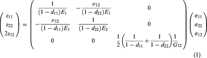
Murakami published a sophisticated book (Murakami, 2012) introducing CDM and proposed a compliance matrix for damaged composite plies with his colleagues (Kanagawa et al., 1996). They used the strain equivalent principle to obtain the following stress–strain relationship
Model 2: Yoshimura model
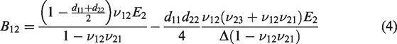
Yoshimura et al. (2011) proposed the concept of the stress equivalent principle to overcome the difficulty of the asymmetry of the compliance matrix. The stress–strain relation can be written as
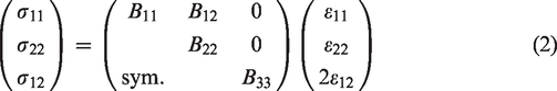


In this case, the stiffness matrix is obviously symmetric. This effective stiffness matrix has already been inserted into the ABAQUS user subroutine to simulate the high-velocity impact problem. The simulation results roughly reproduced the damage progress observed experimentally, but the simulation underestimated the extent of damage compared to the experiments. Moreover, the degradation coefficient of shear modulus does not have any physical meaning. These points are discussed later when comparing the four models explained in this section.
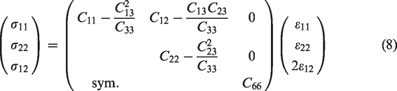
Model 3: Li model
Li et al. (2019) formulated the three-dimensional effective stiffness matrix for a ply with transverse cracking assuming a small damage. The two-dimensional effective stiffness matrix can be written as


Here, ω is the damage parameter related to tensile damage, and ξ is the constant damage parameter related to shear damage. ω and ξ can be expressed as follows (Onodera and Okabe, 2019)
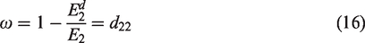
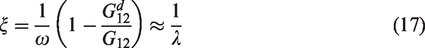
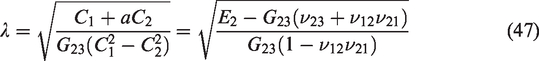
Here, superscript d denotes the property of the damaged ply and λ is the material constant described later. Onodera and Okabe (2019) utilized this effective stiffness for predicting the stiffness reduction and steady-state cracking of laminates with ply cracking. The proposed CDM model agrees with the experimental and numerical results (Onodera and Okabe, 2019). However, the damage parameter ω and transverse crack density have upper limits because a small damage was assumed.
Model 4: Maimí model
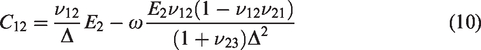
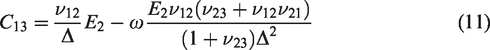
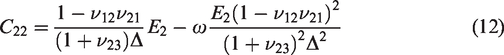
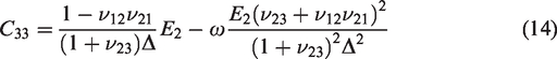
Maimí et al. (2007) proposed the complementary free energy function and thermodynamically derived the effective compliance matrix as follows
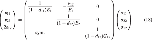
The effective compliance matrix in this case is also explicitly symmetric. However, this case needs an additional damage variable d12 for evaluating the shear stiffness reduction due to transverse cracks or fiber breaks. For the ply with transverse cracks, this parameter is derived from the displacement field of the damaged ply in this study. For the ply with fiber breaks, d12 can be approximated as follows (Murakami, 2012)
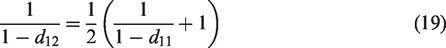
The approximate relation of equation (19) was used when considering the ply with fiber breaks.
Damage variables
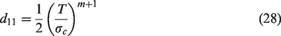
Damage variable d11 for multi-fiber fragmentation
An analytical expression for d11 was developed by employing Curtin’s GLS model (1991) considering the ultimate tensile strength of unidirectional fiber-reinforced composites. Now, we consider the mechanical equilibrium on an arbitrary cross-section in a unidirectional fiber-reinforced composite with broken fibers. Utilizing the shear-lag model, the slip length lf can be described as
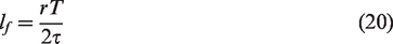

Here, the first term on the right-hand side represents the load carried by the unbroken fiber with the fraction

In the selected cross section, the following mechanical equilibrium condition must be satisfied

σ1 is the stress applied on the unidirectional composite along the fiber direction and f is the fiber volume fraction. Using the Voigt model for representing the Young’s modulus of composite, the unidirectional axial composite stress σ1, axial fiber stress T, and unidirectional Yong’s modulus E1 are expressed as


Here,
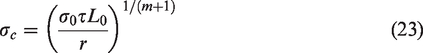
The remaining unknown variable is the far-field fiber axial stress T. Substituting equations (21) and (22) into equation (24), the following nonlinear equation for T was obtained
Stress T at applied load σ1 was numerically obtained by solving the above nonlinear equation. When a cross-ply laminate having

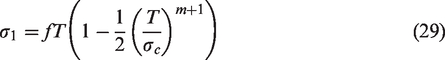
σ1 is the
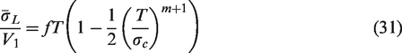
The ultimate tensile strength of cross-ply laminates can be derived using equation (31). The ultimate failure condition of composite laminates is described by the following equation
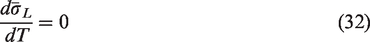
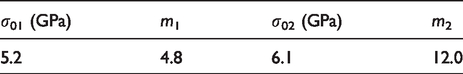
The maximum far-field fiber stress
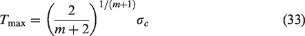
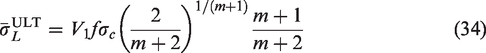
The maximum value of damage variable d11 was obtained using equation (33) in equation (28)
Damage variable d22 associated with transverse cracking
In any of the effective stiffness/compliance models stated above, d22 is necessary to evaluate the compliance/stiffness matrix of the damaged ply. The governing equation (i.e. Laplace equation) of the corresponding problem was derived. The simplified solution of the equation obtained assuming that the displacement field in the longitudinal direction can be expressed as a quadric function. Further, the boundary condition for the governing equation was loosened.
As shown in Figure 1, the solved problem is the displacement field for the damaged transverse ply including periodic matrix cracks having an interval of 2l. These matrix cracks fully propagate in the z-direction and reach the interface. The longitudinal strain of the neighboring ply is assumed to be uniform and unaffected by these cracks. Considering the symmetry of the problem, only the first quadrant in the xy plane was addressed. The plane strain condition was assumed, and the constitutive relations are given by


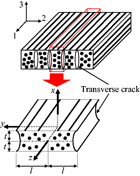
Representative volume element in a cracked ply with transverse crack spacing 2l and ply thickness 2t. (1, 2, 3) is the material coordinate system, and (x, y, z) is the representative volume element coordinate system.
Here, u and v are the displacements along the x and y directions, respectively. C1 and C2 are given by

We assumed that

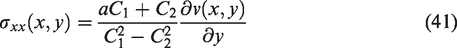
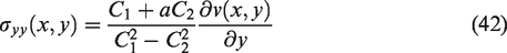
These stresses satisfy the following two-dimensional equilibrium equations
Substituting equations (38) and (41) into equation (43) and removing the trivial case (i.e.
Furthermore, substituting equations (38) and (42) into equation (44), the following governing equation of the displacement field was obtained
The boundary condition of the governing equation is written as


To obtain the simplified solution, the displacement form of the following type was assumed

Using the displacement in equation (52) in equations (48) and (49) yielded


Thus, equation (52) can be written as

Next, our main task was to explicitly determine A(y). The boundary condition of equation (50) gives

However, it is impossible to satisfy the boundary condition of equation (51) exactly as it is. Thus, according to McCartney (1992), the following averaged boundary condition was used
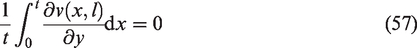
Hence, using equation (55) into equation (57) results in
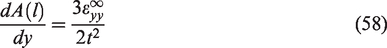
Similar to equation (51), the government equation, i.e. equation (46), cannot be solved directly. Instead of equation (46), the following averaged government equation was here solved
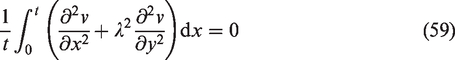
Using equation (55) in equation (59) yielded the following ordinary differential equation
The solution of equation (60) with the boundary conditions in equations (56) and (58) is
Thus, it can be shown that

As stated in our previous paper (Okabe et al., 2018), the damage variable is the ratio of the inelastic strain due to crack opening to the total strain and is finally given by
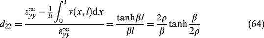

Equation (64) is obviously simpler than equation (65), and loosening the boundary condition equation (51) increases crack opening so that equation (64) gives better predictions than equation (65) in some cases. We will describe this section later through verifications and validations.
Damage variable d12 associated with transverse cracking
When the effective compliance matrix shown in equation (18) is used, the analytical form for damage variable d12 is required. The schematic shown in Figure 1 is also considered here. The neighboring ply deforms under a constant shear strain


Thus, these equations give


The stresses should satisfy the following three-dimensional equilibrium equations
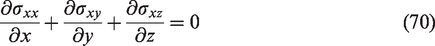
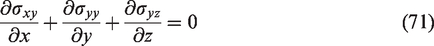
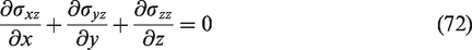
These stresses given in equations (68) and (69) automatically satisfy equations (70) and (71) and lead to the following governing equation derived from equation (72)
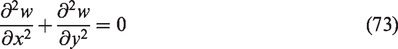
As mentioned in the previous section, the following boundary conditions should be satisfied:


This boundary problem defined by equations (73) to (77) is almost the same as the one defined by equations (46) to (51); therefore, the same derivation procedure can be adopted for this boundary problem. Thus, the displacement field is given by

The shear damage variable d12 can be defined as

Substituting equations (81) and (82) into equation (80), d12 can be rewritten as
The average shear strain is defined by
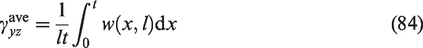
We obtained d12 from equations (78), (83), and (84)
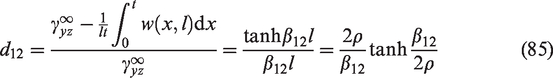
The reduction in shear modulus was initially determined by Hashin (1986), by using the variation approach. Recently, Onodera and Okabe (2019) also obtained the shear damage variable with an infinite series

However, equation (85) is obviously simpler than the infinite series of equation (86).
Effective elastic constants for the damaged composite laminates
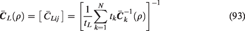
The substitution of damage variables d22 and d12 into equations (1), (2), (8), and (18) gives the effective compliance/stiffness matrix of a ply with transverse cracks as a function of crack density ρ, and fiber breaks can be considered by substituting d11 into equations (1), (2), and (18). The effective stiffness of composite laminates with transverse cracks can be estimated through the CLT using the effective compliance matrix of a damaged ply.
Let us consider the coordinate systems shown in Figure 2. The effective compliance matrix and thermal expansion coefficient of the kth ply having transverse crack density ρ in material coordinate system (1, 2, 3) are defined as


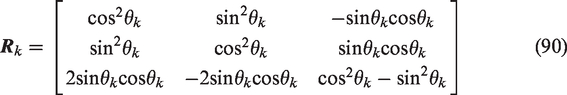
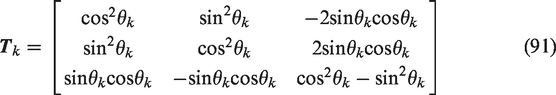

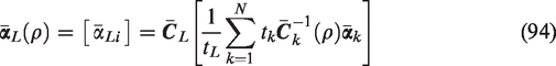
Relationship between the laminate coordinate system (X, Y, Z) and material coordinate system (1, 2, 3).


We can derive the effective elastic constants analytically with the crack density and fiber breaks through the CLT. The stress–strain relationship of damaged laminates can be obtained using equation (92).
Results and discussion
Verification of damage models
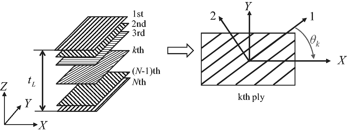
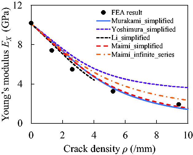
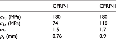
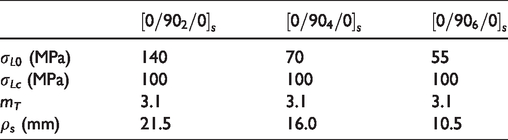
The stiffness reduction in laminates with transverse cracking was studied using five approaches for verifying the effective compliance/stiffness matrices and proposed damage variables d22 and d12. Murakami_simplified shows the Murakami model using d22 expressed in a simplified form in equation (64). Yoshimura_simplified is the Yoshimura model with d22 expressed in a simplified form, identical to Murakami_simplified. Li_simplified is the Li model including the damage parameter ω in equations (16) and (64) and constant damage parameter ξ in equations (17) and (47). Maimí_simplified gives the Maimí model with simplified forms of d22 in equation (64) and d12 in equation (85). Maimí_infinite_series describes the result of the Maimí model with infinite forms of d22 in equation (65) and d12 in equation (86). In Li_simplified, the upper limit of the transverse crack density resulting from the assumption of a small damage postulated in Li’s effective stiffness matrix was determined in the same manner as in our previous study (Li et al., 2019). Table 1 presents the upper limit of the transverse crack density in GFRP laminates used in Li_simplified.
Upper limit of transverse crack density used in Li_simplified.
For verification, comparisons to results obtained using FEA are presented for 


Material constants and thickness of GFRP ply used in stiffness reduction calculation Gudmundson and Zhang (1993).

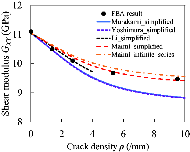
The comparison results are shown in Figures 3 and 4. As for Young’s modulus, all approaches reproduce the tendency of the results observed in FEA. When comparing Maimí_simplified and Maimí_infinite_series, it is shown that the simple forms of equations (64) and (85) yielded results closer to the FEA results than the infinite series forms of equations (65) and (86). Thus, equations (65) and (86) gave smaller crack openings than the FEA results, and loosening the boundary condition may improve the tendency of the crack opening displacement to match with those obtained using FEA. Murakami_simplified, Li_simplified, Maimí_simplified, and Maimí_infinite_series captured the degradation tendency of the Poisson’s ratio; however, Yoshimura_simplified obviously underestimated the degradation. This causes the significant errors in the case of angle-ply laminates because the non-diagonal component directly affects the Young’s modulus of the laminate.
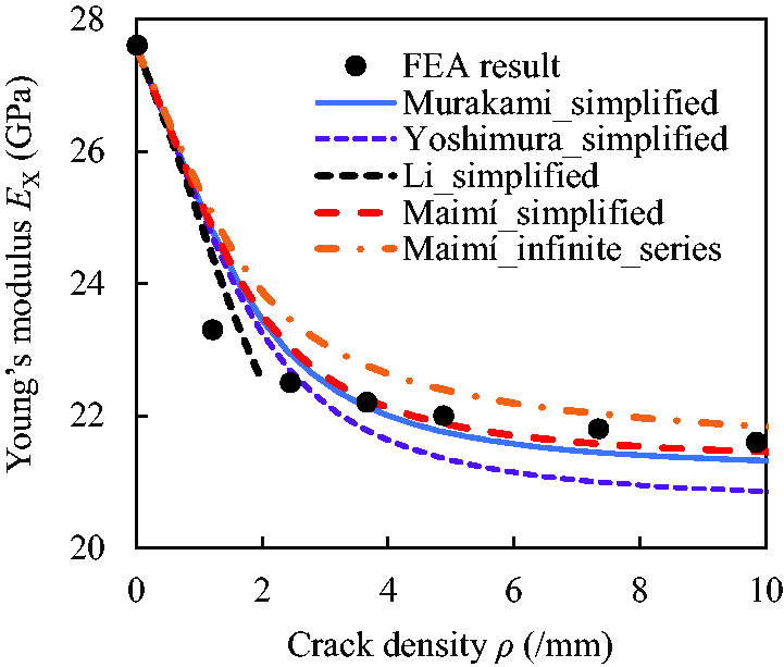
Comparison of Young’s modulus reduction in GFRP
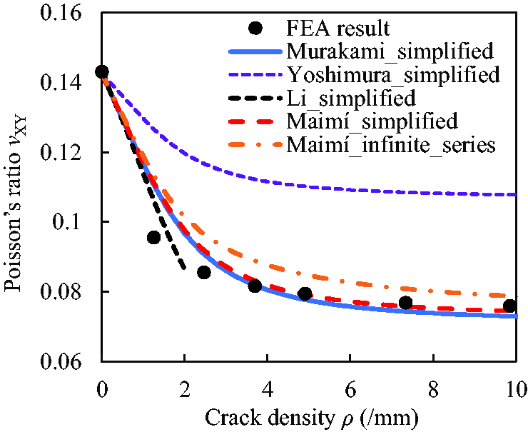
Comparison of Poisson’s ratio reduction in GFRP
Comparison of Young’s moduli of GFRP
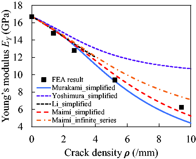
Comparison of Young’s moduli reduction in GFRP
Figuer 7. Comparison of shear modulus reduction in GFRP
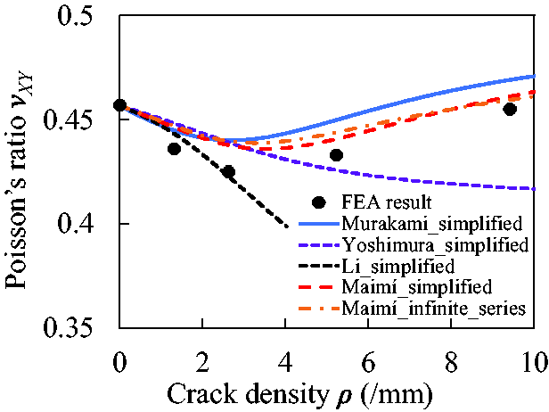
Comparison of Poisson’s ratio change in GFRP
Gudmundson and Zhang (1993) also calculated the stiffness reduction in several types of angle-ply laminates using FEA. The present model was verified by comparison with the results for
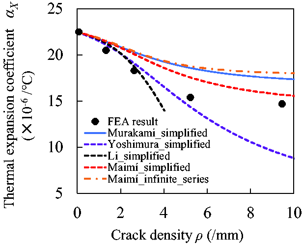
Comparison of axial laminate thermal expansion coefficient reduction in GFRP
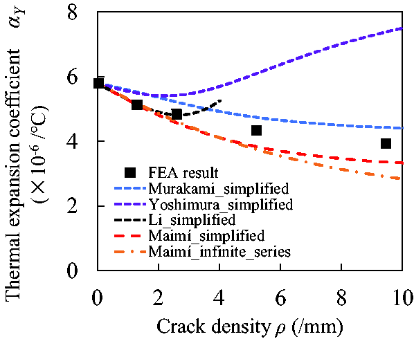
Comparison of transverse laminate thermal expansion coefficient reduction in GFRP
Although the results obtained using all the models agree well with the FEA results, Maimí_simplified shows the best agreement. In fact, we proved that Maimí_simplified is the most appropriate approach among five approaches considering in this study.
Nonlinear stress–strain response of CFRP cross-ply laminates
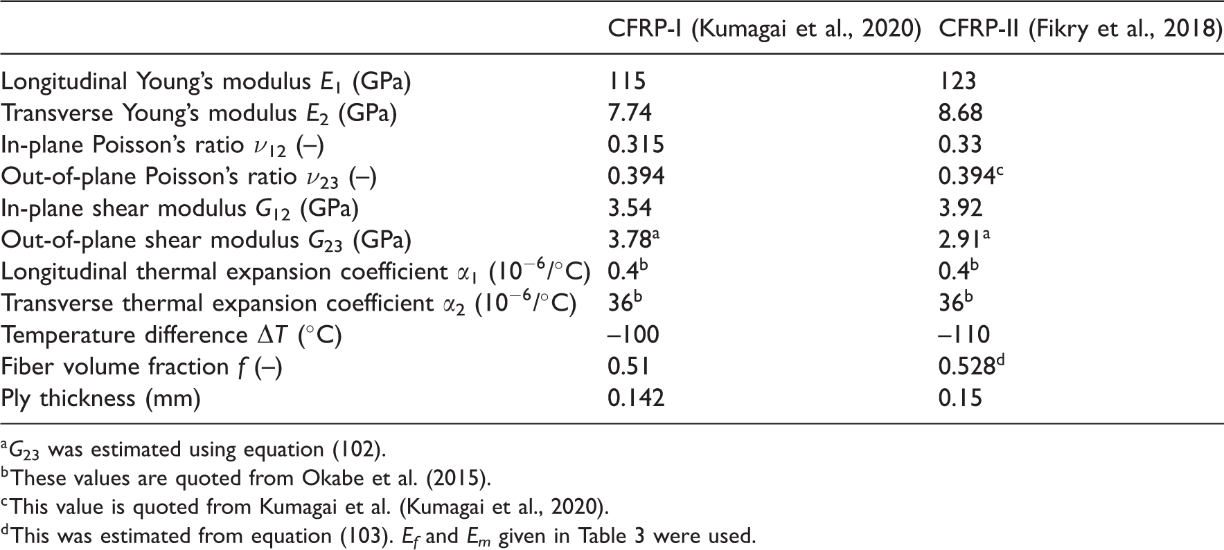
The nonlinear stress–strain response of CFRP cross-ply laminates resulting from transverse cracking was calculated using the present model and compared to the experimental results obtained in this study. We also applied our model to the results reported by Fikry et al. (2018). The stress–strain response of cross-ply laminates with transverse cracking was calculated using equations (92) to (94). From the verification result described in the previous section, the effective stiffness model of Maimí_simplified composed of the Maimí model with simplified forms of d22 in equation (64) and d12 in equation (85) was utilized to predict the stiffness reduction due to transverse cracks in 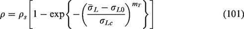
Properties of T700S fiber and resin used in SEM simulations (Okabe et al., 2015).
Bimodal Weibull parameters of the T700S fiber used in SEM simulations ( Yamamoto et al., 2019).
We performed the experiments by ourselves to validate our model presented in this study. Here, we briefly explain the experimental procedures followed to determine the stiffness reduction, transverse crack density, and stress–strain curves of the cross-ply laminates. Loading and unloading tests were conducted to obtain the nonlinear stress–strain response of cross-ply laminates, transverse crack density in
The stress–strain relationship for the T700S/2592 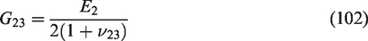
Mechanical properties of plies used in the calculation of stress-strain behavior of cross-ply laminates.
Simulation results of ultimate fiber failure strain at stress concentration factor of 1.9.
Parameters of transverse crack evolution in CFRP laminate used in equation (102).
Parameters of transverse crack density evolution were determined by fitting the calculated results of the present model with the experimental data as shown in Figure 11(a). Figure 11(b) presents a comparison of the predicted results for stiffness reduction as a function of transverse crack density determined by using the present model with experimental results. The results predicted using the present model agree quantitatively with the experimental results obtained through loading/unloading tests. The predicted stress–strain responses of the T700S/2592
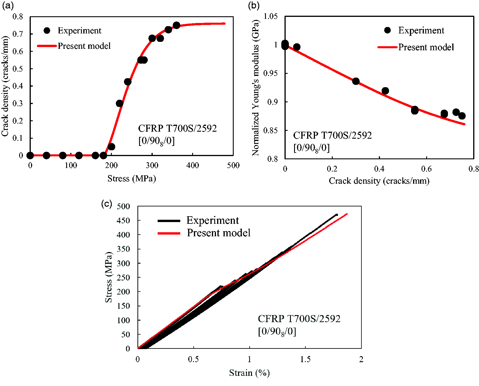
Comparison of results predicted using present model for (a) transverse crack density evolution, (b) stiffness reduction, and (c) stress–strain response of T700S/2592
The nonlinear stress–strain behavior of the T700SC/2592 
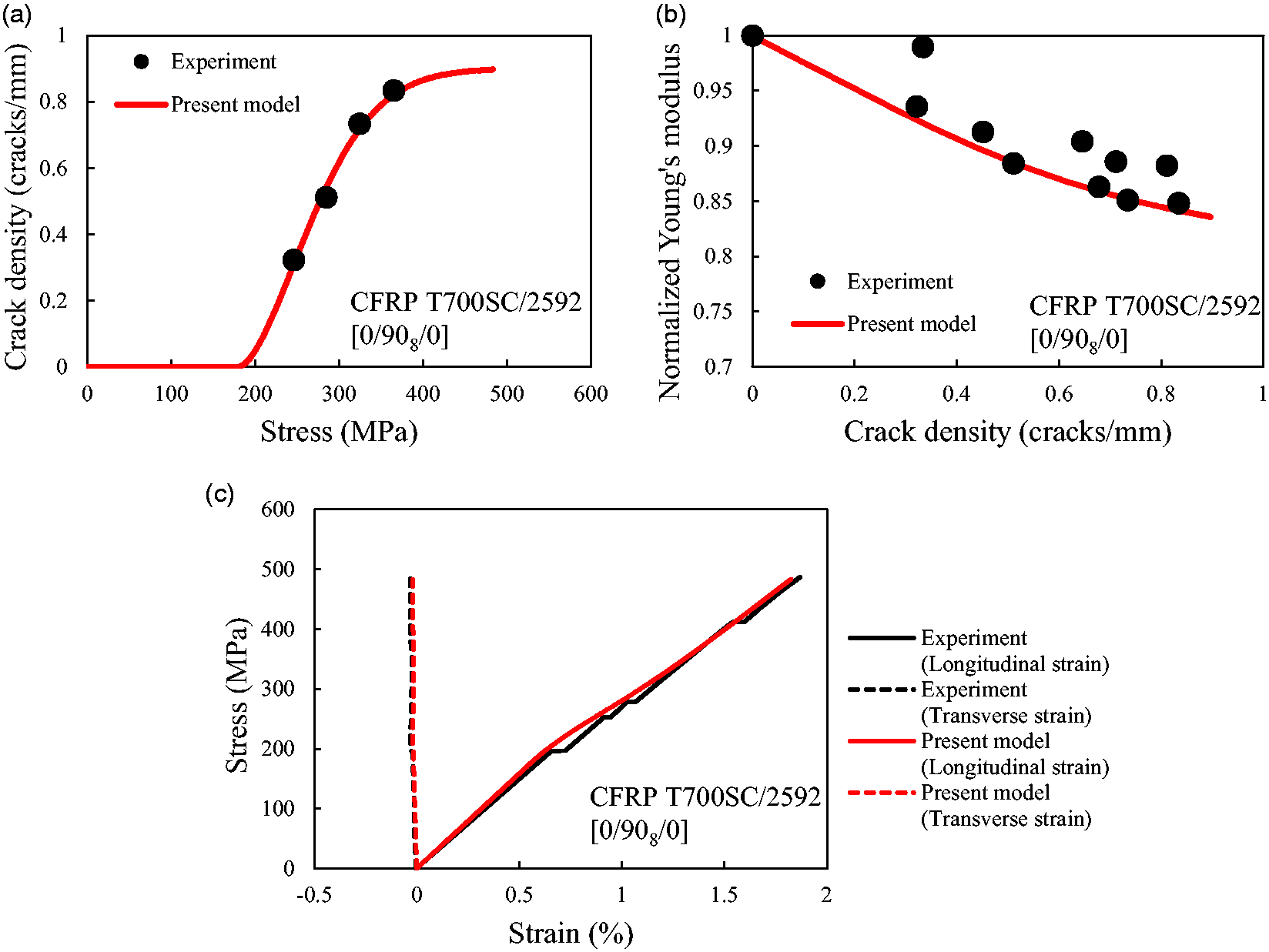
Comparison of (a) transverse crack density, (b) stiffness reduction, and (c) stress-strain response of T700SC/2592
Nonlinear stress–strain response of GFRP cross-ply laminates
The nonlinear stress–strain behavior of E-glass/TX24235 GFRP
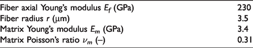
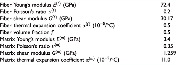
The GFRP ply properties were estimated using the analytical model developed by Kravchenko et al. (2017). According to them, the properties of unidirectional-fiber-reinforced ply composed of the transversely isotropic fibers and the isotropic matrix are determined as follows
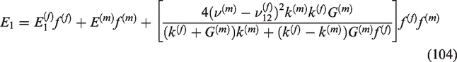
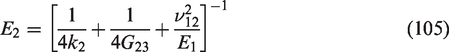
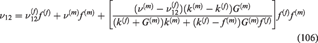
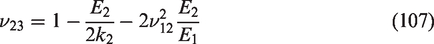
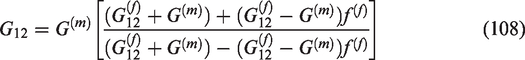
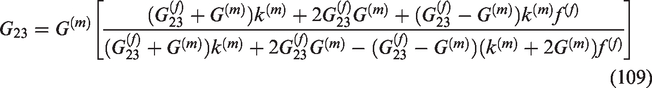
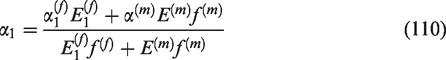

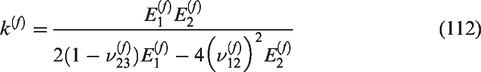
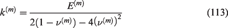

Here, superscripts (f) and (m) denote the fiber and matrix property, respectively. Subscripts 1, 2, and 3 represent the material coordinate axis of the ply shown in Figure 1. E, G, ν, α, k, and f are the Young’s modulus, shear modulus, Poisson’s ratio, thermal expansion coefficient, bulk modulus, and volume fraction, respectively. k2 is the transverse plane bulk modulus.
Material properties of E-glass fiber and resin (Malik, 2011).
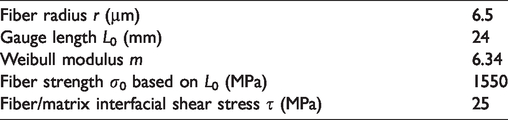
Material properties used for calculating d11 (Zhao et al., 1974).
Parameters of transverse crack evolution in E-glass/TX24235 GFRP
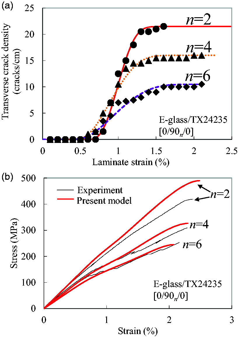
Comparison of (a) transverse cracking progression and (b) stress-strain responses of E-glass/TX24235 GFRP
Figure 13(b) shows the comparison of the stress–strain responses of E-glass/TX24235 GFRP
Conclusions
This study involved deriving a new analytical model for predicting the effective compliance of composite laminates and simplified expressions for the damage tensor. We evaluated four models that yielded asymmetric/symmetric compliance matrices of damaged composite plies. Damage variable d11 describing stiffness reduction due to fiber breaks and its upper bound
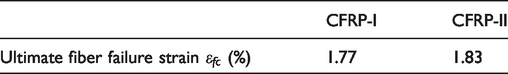
The nonlinear stress–strain behaviors of CFRP cross-ply laminates resulting from transverse cracking were predicted using the present model, and the predicted results are compared with the experimental results. The effective compliance model with simplified damage variable d22 and d12 was utilized to calculate the stiffness reduction of the CFRP laminates. The ultimate tensile strength of CFRP cross-ply laminates was predicted based on a strain-based fiber failure criterion because fiber fracture in CFRP laminate occurs at the ultimate laminate failure stress. We assumed that the laminate failed when the effective axial laminate strain became equal to the ultimate fiber axial failure strain in
We predicted the nonlinear stress–strain behavior of
Footnotes
Acknowledgements
We would like to thank S Date (Tohoku University) for his support in conducting the SEM simulations. We would also like to express our appreciation to S Kochii (Tohoku University) for his assistance while performing experiments. The authors would like to thank Editage (![]() ) for English language editing.
) for English language editing.
Declaration of conflicting interests
The author(s) declared no potential conflicts of interest with respect to the research, authorship, and/or publication of this article.
Funding
The author(s) disclosed receipt of the following financial support for the research, authorship, and/or publication of this article: The authors disclosed receipt of the following financial support for the research, authorship, and/or publication: Council for Science, Technology and Innovation (CSTI), Cross-ministerial Strategic Innovation Promotion Program (SIP), “Materials Integration” for revolutionary design system of structural materials (Funding agency: JST); University of Washington-Tohoku University: Academic Open Space (UW-TU: AOS); Toray Industries, Inc.; JSPS KAKENHI Grant No. JP 18J20899.