
Abstract
Microbially induced calcite precipitation (MICP), a sustainable approach for sand biocementation, was investigated in previous studies based on metabolic activity of individual microorganisms. The individual bacteria, specifically Sporosarcina pasteurii (SP), Bacillus subtilis (BS), and Lysinibacillus sphaericus (LS), were found capable enough for sand biocementation. However, present study investigates synergistic effects of using bacterial-hybrids on cementation and consequent improvement in sand properties. The SP, BS, and LS strains were used in different combinations to create bacterial-hybrids and applied under simulated non-sterile field conditions. Initially, sand biotreatment was carried out in plastic tubes up to 14 days, using bacterial mixtures and 0.5 M cementation solution. Biocemented specimens were tested for calcite precipitation, XRD, FTIR, and SEM. The SP and LS combination (SPLS hybrid) showed maximum calcite precipitation, which is further used for biotreatment to create cylindrical sand samples for testing improved engineering properties. These samples were prepared using 0.5 M cementation solution in three pore volumes (1, 0.75, and 0.5 PV) and treatment cycles (12, 24, and 48 hrs TC) up to 18 days. Biocemented samples were tested for permeability (6th, 12th, and 18th days of biotreatment), unconfined compressive strength (UCS), split tensile strength (STS), ultrasonic pulse velocity (UPV), and consolidated undrained stress-strain response. Durability of biocementation was also investigated by determining reduction in strength and UPV subjected to freeze-thaw (FT) cycles (5, 10, 15, and 20). The results showed maximum UCS of 1902 kPa, STS of 356 kPa, UPV of 2408 m/s, and coefficient of permeability reduction up to 91%. The higher results were achieved with 11.11% calcite content in 1PV-12TC treated samples. The 1PV-12TC treated samples resulted in 4.2%, 8.3%, 17%, and 35% reduction of strength after 5, 10, 15, and 20 FT cycles, respectively. Overall, biocementation using hybrid bacteria is shown significant to improve sand's engineering properties, including potential to mitigate liquefaction.
Keywords
Introduction
The earthquake-induced liquefaction in sandy soils causes extensive damage to the substructures and superstructures. There are various conventional methods, such as soil replacement, solidification and grain bonding through grouting, in-situ densification of soil, reduction in the degree of saturation, and use of drains (Sharma et al., 2021a). However, each of these conventional methods has certain limitations related to its adverse effect on the environment, energy intensive, and time consuming. The replacement of soil is not feasible for large field applications. The soil must be available in close proximity for replacing the liquefiable soil; otherwise, the transportation costs might become excessive. The grouting and deep soil mixing using cement and chemicals are carbon-intensive and non-environment friendly. The chemical grouts may pollute groundwater and create poisoning effects; hence they are banned in many countries (Karol, 2003). The in-situ densification methods are limited to shallow depths, and they also pose stability concerns to surrounding structures. The degree of saturation reduction using dewatering is difficult and expensive, which requires to maintain continuous pumping. The use of drains does not mitigate the settlements due to cyclic loading. Recently, conventional methods are replaced by advanced emerging techniques for improving the properties of granular soils. The use of supplementary cementitious materials, nanomaterials, synthetic fibers, industrial waste products, and biopolymers are found effective for strength enhancement (Huang and Wang 2016; Tiwari and Satyam, 2019, 2020; Tiwari et al., 2020a, 2020b, 2020c). However, the high cost of treatment and field application of these methods are the major challenges.
Microbiologists, geologists, geotechnical and chemical engineers have recently investigated the potential of microorganisms to cement the soil grains. The technique is based on nature’s biology conception, which can overcome the disadvantages of conventional soil improvement methods, including liquefaction mitigation (DeJong et al., 2006). The bacteria present in soil reacts with available urea and calcium sources to produce calcite precipitation. The bacteria excrete the ureases enzyme, which expedites the urea hydrolysis process and produces ammonia and carbonate ions (equation (1)). The Ca2+ ions generated through the calcium source get attached to bacteria cells and create a cell-Ca bond (equation (2)). The cell-Ca bond further reacts with carbonate ions and produces cell-attached calcite precipitation (equation (3); Cardoso et al., 2020; Mitchell and Santamarina, 2005). The calcite precipitation takes place on the surface of sand particles and between the voids of sand grains. Thus, the calcite precipitation, also known as microbially induced carbonate precipitation (MICP), improves the engineering properties of sand. Several studies support the potential of MICP for liquefaction mitigation, as the method increases shear strength and reduces the permeability of sand (Burbank et al., 2011; DeJong et al., 2006, 2013; Feng and Montoya, 2017; Riveros and Sadrekarimi, 2020; Xiao et al., 2019; Zamani and Montoya, 2019). The cyclic triaxial and cyclic simple shear tests on biocemented sands showed a significant increase in liquefaction resistance. The number of cycles to trigger the liquefaction hazard increases more than 10-folds in biocemented sands as compared to untreated sands (Lee et al., 2020; Sharma et al., 2021a; Xiao et al., 2018, 2019). However, the biotreatment requires careful optimization of process controls (presence of different bacteria, cementing solution, application method, non-sterile conditions, and temperature), which are not yet fully explored. Moreover, the durability of biocemented sands also needs to be assessed.


The biocementation can be targeted either by biostimulation or bioaugmentation (Ferris et al., 2004). In general, the urease enzyme is commonly found in various plants and microbes. Bacteria are the most abundant microbe in soils. The risk of any environmental hazard is reduced as the bacteria are native to earth. The ample bacteria strains are competent enough to produce urease enzyme and generally used in the MICP technique. Sporosarcina pasteurii is a widely used gram-positive, non-pathogenic, alkalophilic, and highly active urease producing soil bacterium (Bang et al., 2001; DeJong et al., 2006). Various other bacterial species, such as Bacillus/Lysinibacillus sphaericus (De Muynck et al., 2010; Moravej et al. 2018), Bacillus subtilis (Gat et al., 2014), Bacillus lichenformis (Helmi et al., 2016; Saricicek et al., 2019), Bacillus megaterium (Jiang et al., 2017), and Proteus vulgaris (Whiffin, 2004), were used in recent studies for the comparison and capability of MICP (Sharma et al., 2021b). However, the effect of the presence of multiple ureases producing bacteria as a hybrid metabolic activity is not explored yet.
The frost action is considered as an influential cause of deterioration of concrete and porous materials exposed to the environment in cold regions (Litvan, 1980). The concrete and soils in cold regions are exposed to freezing and thawing cycle at least once every year. The concrete is heterogeneous and quasi-brittle material, which shows surface scaling and internal damage after repeated freeze-thaw cycles (Dong et al., 2018; Luo et al., 2018). On the other hand, the freeze-thaw cycles significantly change the geotechnical properties of soil (Eigenbrod et al., 1996; Viklander, 1998). The destruction of porous materials because of freeze-thaw cycles has been a major interest to geotechnical engineers for more than 200 years. Thus, considering the biocemented sand as a porous material, it is necessary to explore the effect of freeze-thaw cycles in detail. The retention of permeability is one of the major advantages of MICP technique, which allows immediate mass-transfer of water throughout the biocemented sand. However, consecutive freeze-thaw cycles may lead to the generation of microcracks due to tensile stresses during frost action (Cheng et al., 2017; Liu et al., 2019). Hence, the microcracks generation, strength reduction, and damage of biocemented sand due to freeze-thaw cycles are required to be investigated.
The present study aims to achieve calcite precipitation in the presence of multiple ureases producing bacteria through their hybridized activity. Experiments were conducted with the augmentation of bacteria cultures (SP, BS, and LS) in mixed combinations in poorly graded sand using a plastic tube setup. The biotreatment was carried out up to 14 days using 0.5 M cementation solution and 12 hrs of the treatment cycle. The biocemented specimens were tested for calcite precipitation, and the morphology of calcite crystals was analyzed using microcharacterization methods (SEM, XRD, and FTIR). The SPLS combination of hybridized activity was found effective for the MICP process. Additional testing was conducted using SPLS mixture in sand columns using cementation solution (urea and calcium chloride dihydrate), different treatment cycles, and different pore volumes, with treatment duration up to 18 days. The effectiveness of biotreatment was assessed by testing calcite content, UCS, STS, UPV, stress-strain response, and durability (with freeze-thaw cycles). The results helped to identify the optimal conditions for biotreatment to be effective, efficient, and cost-effective for the calcite formation and strength enhancement of sand for large scale applications.
Materials and methods
Sand
Locally available river sand, collected from an excavation site near Indore city (India), was used for this study. The collected sand was oven-dried at 105°C for 24 h. The particle size analysis was conducted as per the IS: 2720 (Part IV)-1985. The grain size distribution of sand shows that it lies between the boundaries of potentially and most liquefiable soils, which signify that the untreated sand is susceptible to liquefaction under seismic conditions (Figure 1) (Tsuchida, 1970). The curvature coefficient (Cc) and uniformity coefficient (Cu) of sand were calculated as 0.72 and 2.60, respectively. The mean grain size (D50) was 0.32 mm. According to the IS classification system (IS:1498-1970 2002), the sand was classified as poorly graded sand. The relative density of sand was determined according to IS: 2720 (Part XIV)-1983 and calculated in the range of 35–40%. The specific gravity of sand was 2.65, which was analyzed as per the IS:2720 (Part III/Sec 1)-1980.
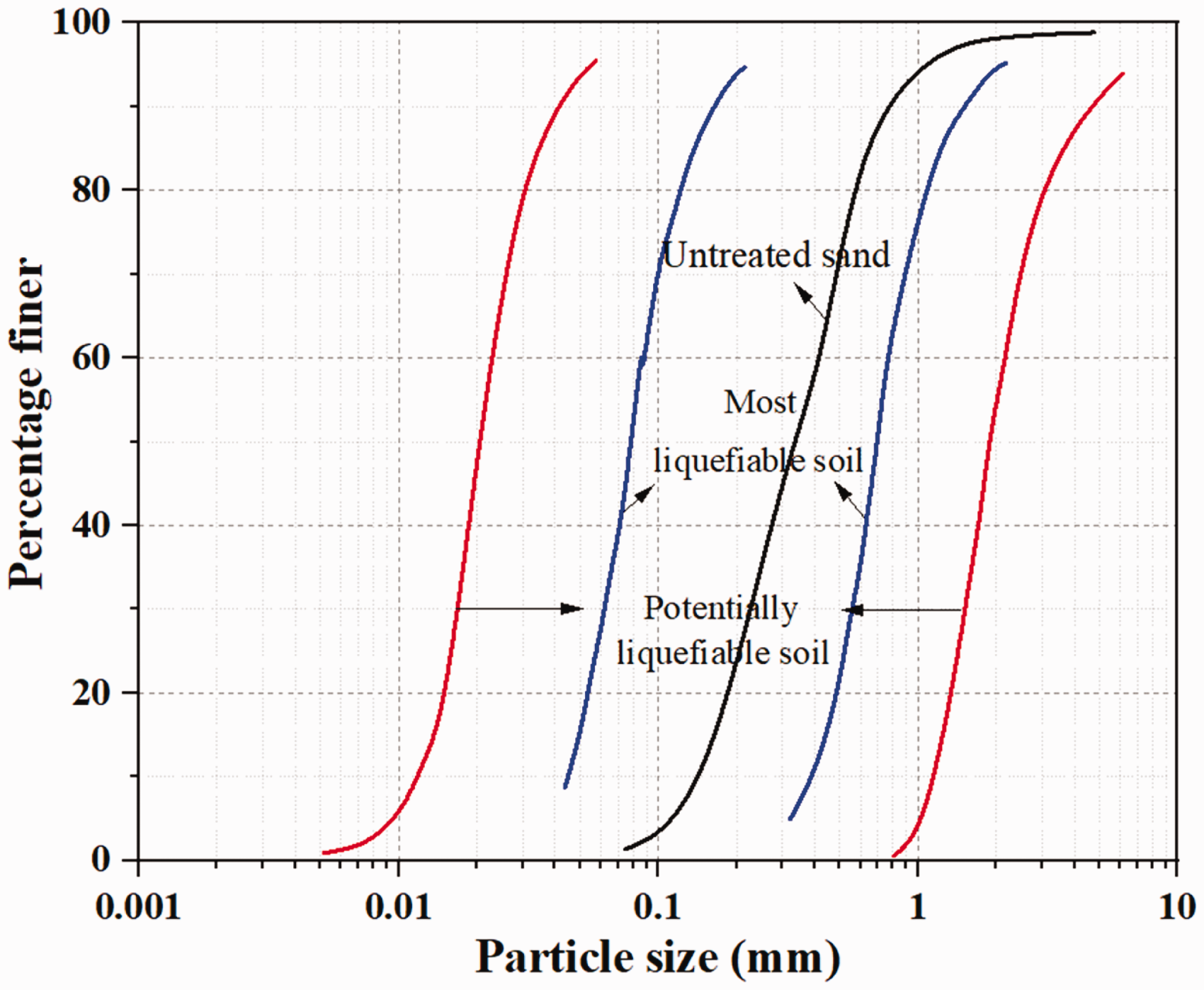
Particle size distribution of sand superimposed with liquefiable soil boundaries.
MICP is considered to be an option to increase mechanical properties and liquefaction resistance of the sand. The geometric compatibility of soil particles is one of the primary considerations to apply the MICP method. The pore throats of soil strata must include significant spaces so that the bacteria (size of 0.5–3 µm) simulation or augmentation can be carried out effectively (Madigan and Martinko, 2003). Moreover, the soil should possess relatively higher permeability to inject bacterial and cementing solutions. Based on the constant head method of hydraulic conductivity testing as per IS 2720 (Part 17): 1986, the hydraulic conductivity of sand was determined as 2.74 × 10⁻⁶ m/s, and the porosity was calculated as 40.3%. Thus, the bacterial size, sand particle size, along with hydraulic conductivity, and porosity of sand are all found to be conducive for implementing the MICP method.
Bacteria cultivation procedure
The bacteria species of Sporosarcina pasteurii (SP) (ATCC 11,859), Bacillus subtilis (BS) (ATCC NCIB 8533), and Lysinibacillus sphaericus (LS) (ATCC 14,577) were procured from National Collection of Industrial Microorganisms (NCIM), India. The strains were preserved at –20°C. These bacteria strains are urease producing, gram-positive, soil-based, alkalophilic, and non-pathogenic. The soil-based bacteria strains were chosen to simulate indigenous field conditions. If any of these strains are present in soil individually or in combination, then the biostimulation approach can be carried out. The presence of a particular strain at a site can be investigated through DNA sequencing, PCR, and gram staining methods (Yargicoglu and Reddy, 2015). If these bacterial strains are not found in-situ in the sand, bioaugmentation will be required, which involves the injection of the selected cultivated bacterial strains.
The bioaugmentation method was used in this study, and Figure 2 shows the stepwise process of the bacteria cultivation (SP, BS, and LS) and harvesting them as pellets. The nutrient broth (NB), with composition as summarized in Table 1, was used in Step1 to prepare solution for bacteria inoculation. Initially, tube testing was carried out under sterile and environmentally controlled conditions. Thus, according to the steps mentioned in Figure 2, the bacteria cultivation was conducted for bioaugmentation in tube setup.
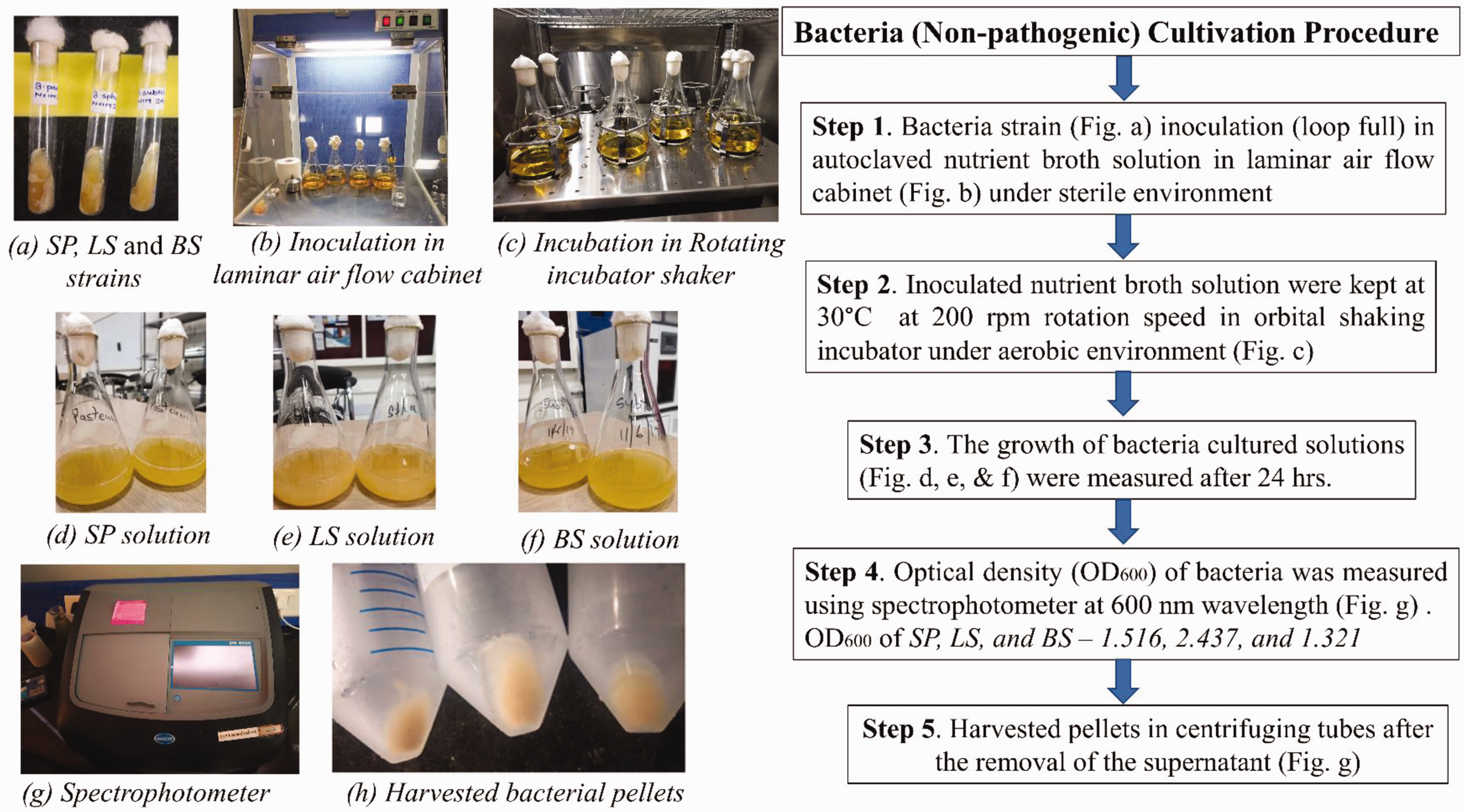
Detailed bacteria cultivation procedure used in this study.
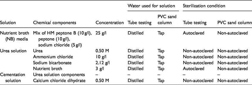
Components of chemical solutions with their concentrations, type of water used for solution preparation, and sterilization conditions used in this study.
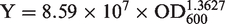
However, for the second part of study, which includes macroscale engineering properties investigation, the non-sterile conditions that represent typical field conditions, were adopted in bacterial cultivation. The nutrient broth solution was prepared using tap water as in step 1 (Figure 2). The autoclaving was also not conducted, as it will not be possible for large scale bacteria cultivation. The SP and LS strains were inoculated for augmenting in PVC sand column setup. The incubation (Step 2) was similar to the initial process. It was found in step 3 that the significant bacteria cell density was achieved. The optical density (OD600) of bacteria strains was measured through a spectrophotometer at a wavelength of 600 nm. Thus, OD600 of SP and LS strains were found as 1.114 and 2.145, respectively (Step 4). The number or concentration of bacteria cells can be calculated by OD600, which signifies the growth of living bacteria cells after the incubation process. The concentration of bacteria cells (Y) present in per ml of solution can be calculated using the following formula (Fredrickson and Fletcher, 2001; Ramachandran et al., 2001)
Step 5, for the centrifugation of bacterial solution, removing supernatant and replacement with a fresh nutrient solution was avoided to save the cost, energy, and time. In the case of large-scale application, centrifugation will be difficult; thus, step 5 was not used for application in the PVC pipe setup. The cultured bacteria solution was augmented directly without centrifugation.
Chemical solutions
Table 1 summarizes all the chemical solution with the components and concentrations used in this study. The 0.5 M concentrations of urea and CaCl2.2H2O were used to achieve a uniform and significant calcite precipitation (Wen et al., 2019). The type of water used for solution preparation and solution sterilization condition are also shown in Table 1 for both tube and PVC sand column treatments. The urea and cementation solution includes sodium bicarbonate and ammonium chloride to act as buffer (Bu et al., 2018). The urea was not autoclaved as it decomposes at higher temperatures because of the changes in chemical structure (Saricicek et al., 2019). Initially, for tube testing, only NB was autoclaved to avoid any other bacterial contamination (Mortensen et al., 2011). Later, the NB solution was also not autoclaved to simulate a practical approach to large-scale field applications.
Sample preparation and MICP treatment process
The testing program was divided into two parts:
The first part of testing was aimed to investigate the capability of the mixture of three different bacteria combinations for hybridized activity and MICP process. The second part investigated the augmentation of SPLS mixture (selected from the previous testing results) and analysis of macro-scale engineering properties along with the durability of biocemented sand.
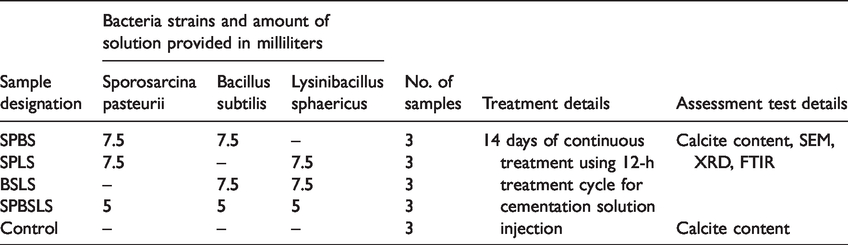
The first part of testing included performing the tube testing program, as summarized in Table 2. It can be seen that different combinations of three selected bacteria (hybrid bacteria) were selected to systematically assess the synergistic or antagonistic effects on biocementation. The step-by-step description of the biotreatment procedure is explained in Figure 3. The sand was oven-dried (at 105°C for 24 h) to minimize the effect of any other soil bacterium and chances of contamination. This has been conducted to ascertain the effects of augmented bacterial strains. The oven-dried sand was filled in the tubes at a target relative density of 40%. The control samples were also prepared to explore the effect of cementation solution injection in the absence of urease producing bacteria. Steps 1, 4, and 5, shown in Figure 3, were applied to prepare the control samples. The laboratory temperature was not controlled during biotreatment to simulate field conditions. After the predetermined treatment time, all of the tube samples were extruding from tube molds and oven-dried. The oven-drying was carried out to cease any bacterial activity.
Sample details for initial tube testing carried out to investigate different hybrid bacteria strain mixes.
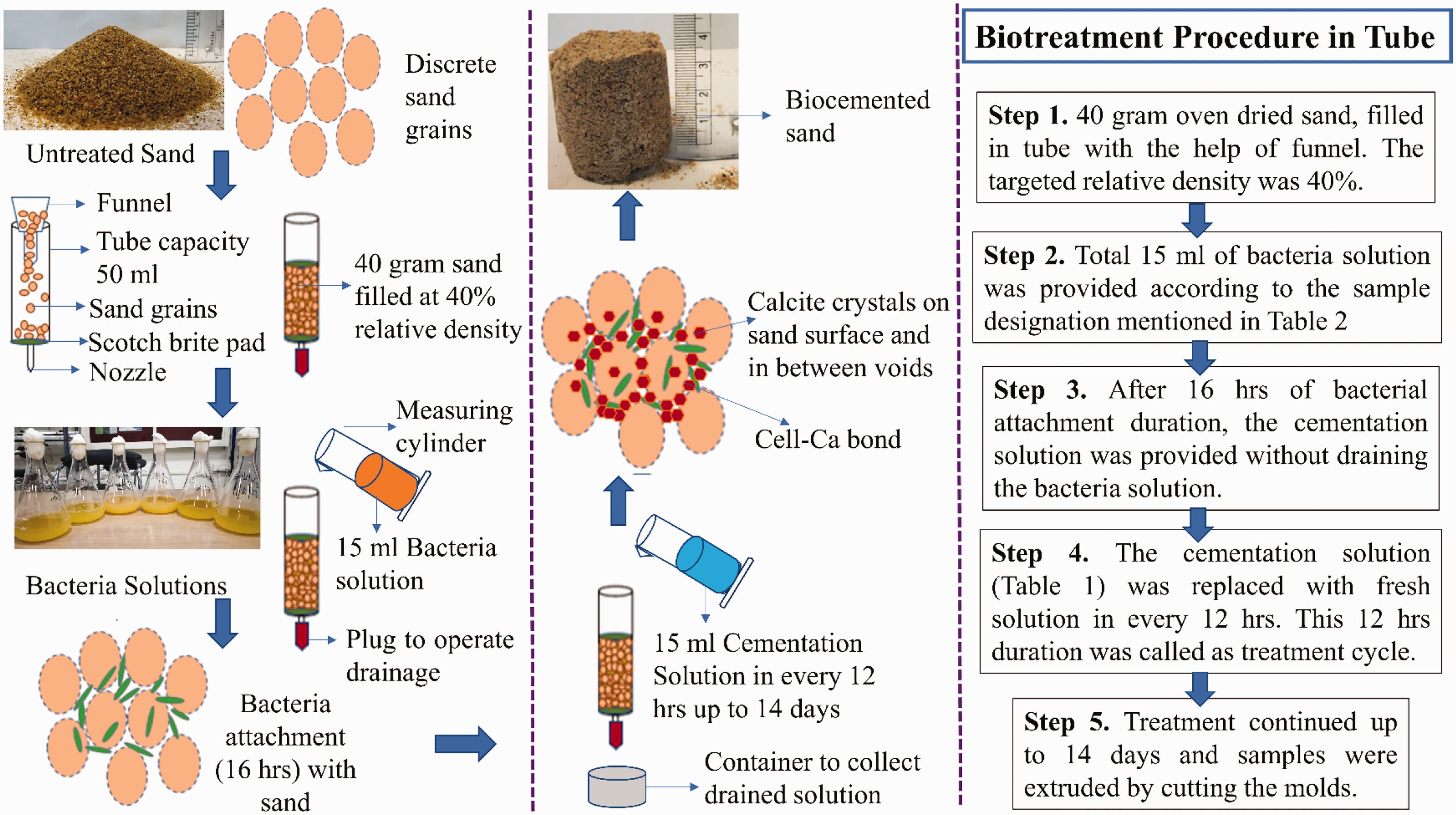
Biotreatment procedure for tube testing setup for hybridized activity analysis.
The details of the second part of the testing program, including the type of specimens and tests conducted, are summarized in Table 3. Based on part one testing, the hybrid bacteria of SP and LS was selected for this testing. The biocemented sample preparation, for destructive and non-destructive testing (for determining engineering properties) and FT analysis, is shown in Figure 4. The preparation of samples for biotreatment consisted of the following steps:
Details of PVC sand column samples treated with hybrid SP and LS strains.a
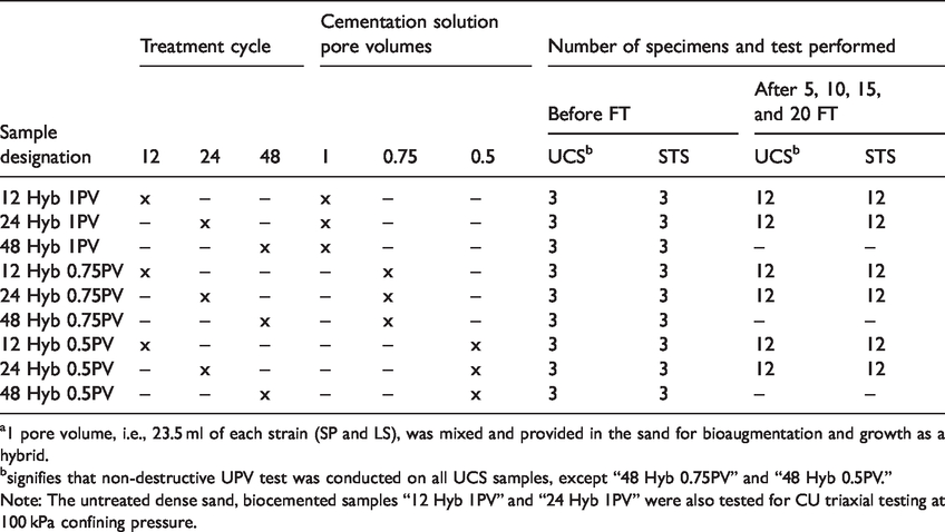
a1 pore volume, i.e., 23.5 ml of each strain (SP and LS), was mixed and provided in the sand for bioaugmentation and growth as a hybrid.
bsignifies that non-destructive UPV test was conducted on all UCS samples, except “48 Hyb 0.75PV” and “48 Hyb 0.5PV.”
Note: The untreated dense sand, biocemented samples “12 Hyb 1PV” and “24 Hyb 1PV” were also tested for CU triaxial testing at 100 kPa confining pressure.
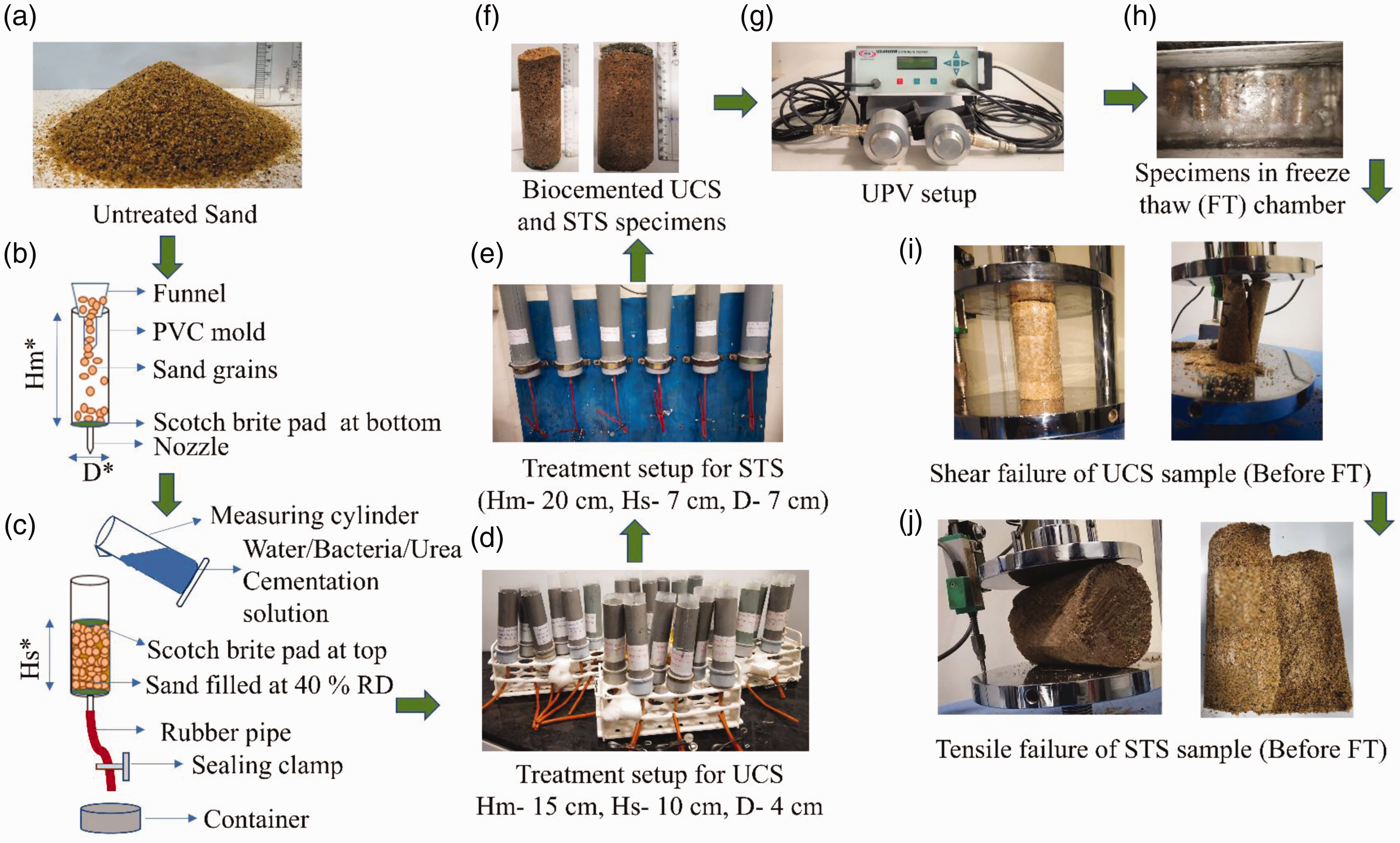
Procedures for biocemented sample preparation for UCS, STS, UPV, and durability (freeze-thaw cycles) testing.
The oven-dried sand was used to fill at a targeted relative density of 40% in PVC molds. The oven-dried sand is shown in Figure 4(a).
The PVC molds were open from the top, and a brass nozzle was provided at the bottom to operate drainage.
The PVC mold diameter was 4 cm and 7 cm for UCS and STS test sample preparation, respectively. A scotch brite was placed at the PVC mold bottom, which acted as a filter. The inner diameter of the mold was covered with the polythene to ensure the easy removal of biocemented sand after treatment. A funnel was used to fill the sand in all PVC molds at 40% relative density (RD). The mold height was higher than the sample height to create ponding of solutions during biotreatment. The described arrangement is shown in Figure 4(b).
The sand was filled up to the desired height, and the scotch brite was placed above it. The brass nozzle was connected with a rubber pipe to drain the solutions. A sealing clamp was used to close the rubber pipe. The solution injections at a particular time interval were carried out using graduated measuring cylinders. The pictorial representation of this procedure is shown in Figure 4(c).
The aspect ratio (length to diameter) of 2:1 and 1:1 was ensured for UCS and STS specimens, respectively. UCS specimens' height was kept slightly higher, as the biocemented sample ends need smoothening before UCS testing for uniform loading. The PVC sand column setups for biotreatment are shown in Figure 4(d) and (e).
According to the sample preparation steps mentioned above, the biotreatment was carried out after filling the sand into molds. The procedure for biotreatment was as following:
Two pore volumes of tap water were filled in all the molds to allow the air expulsion and create full saturation. The UCS and STS molds were filled with 94 ml and 202 ml of filtered tap water, respectively. The ponding was created above the top of the sample. When the air expulsion was stopped after some time, then the clamps were opened to allow the drainage of tap water (Mahawish et al., 2019). The sealing clamps were closed after draining the water. One pore volume of bacteria solutions was augmented in saturated sand. The SP and LS solutions of 23.5 ml each were mixed and poured into the sand. The bacterial mix solution was allowed to hold for 24 h for hybrid activity and cell-sand grain attachment. The time period was called attachment time. The attachment time was increased from 16 to 24 h in initial tube testing to sand sample treatment in PVC tubes. The bacteria attachment time was increased to ensure the uniformity in bacteria growth and attachment throughout the sand specimen. The uniform bacteria attachment leads to create uniform cell-Ca bonds and calcite precipitation (Sharma et al., 2020). The bacteria solutions were injected only at the starting of biotreatment. A portion of nutrient broth (3 g/l) was added in urea and cementation solutions (Table 1), which served as food for bacteria mix and ensured further hybrid growth. One pore volume of urea medium was provided in each specimen after the attachment period, but the bacteria solution was not drained. The urea medium was held in all specimens for the next 24 h. This step was termed as simulation time. In this duration, the urea hydrolyses occur in the presence of urease and forms the carbonate ions uniformly in the sand matrix. After the completion of simulation time, the solutions were drained, and cementation solutions were injected according to the details mentioned in Table 3. Here, a treatment cycle is a duration up to which the cementation solution was held in the mold. After every treatment cycle, the previously poured solution was drained, and a new cementation solution was injected. The temperature of the laboratory was not controlled during the biotreatment, similar to tube samples treatment. This treatment method of injection cementation solution at a particular interval is known as the stop-flow injection method. The stop-flow injection method was found more effective than the continuous-flow injection method to achieve uniform calcite precipitation (Barkouki et al., 2011). The treatment was repeated with different treatment cycles and different pore volumes of cementation solution up to 16 days of total treatment duration. The biocemented sand samples were extruded from molds by air pressure application from the nozzle. The placement of polythene at the inner diameter of mold ensured the easy removal of specimens. The typical biocemented specimens are shown in Figure 4(f). Similar to tube extruded biocemented specimens in part one, biotreated sand samples were extruded from PVC columns and oven-dried at 105°C for 24 h.
The consolidated undrained (CU) triaxial testing was conducted on untreated dense sand, “12 Hyb 1PV,” and “24 Hyb 1PV” samples to understand the typical stress-strain response. The untreated sand sample's targeted density was 1.75 g/cm3, which is the maximum dry density of sand. The dense sand sample of diameter 5 cm and height 10 cm was prepared using the moist tamping method. The biocemented samples were prepared in 5 cm diameter and 20 cm height cylinder setups. The similar sample preparation and treatment procedure was adopted for biocemented specimens for triaxial testing. The biocemented specimens of 5 cm diameter and 10 cm height were prepared from the samples extruded from molds after biotreatment.
Calcite content and microcharacterization of tube samples
The calcite content of biocemented specimen was determined using Fann calcimeter gauge. The sub-sample for calcite content measurement was collected from the center of each biocemented specimen and its replicates. The calcite precipitated sand was placed in the reaction cell of calcimeter and allowed to react with HCl. As a result of CaCO3 and HCl reaction, CO2 gas was generated. The carbon dioxide gas creates pressure in the reaction cell, which can be noted in the pressure gauge. The reading of pressure gauge was used to calculate the calcite percent in sample (Kalantary et al., 2019).
The microstructural changes in biotreated sand samples were analyzed using scanning electron microscopy (SEM), X-ray diffraction (XRD), and Fourier transform infrared spectroscopy (FTIR). The biocemented sand specimen was broken into small sizes so that the cementation between particles and on sand particle surface can be captured through SEM. The broken specimens were placed on carbon tape fixed stubs. The specimens were coated with gold sputter to make them conductive. The SEM imaging was conducted at 15 kV at similar magnification and scale. The presence of calcite mineral and calcite crystal structure were explored through XRD analysis with a scanning range of 10°–90°. The HighScore Plus software was used to perform peak analysis. The separate peaks of minerals can be identified through the software. The chemical bond formation in biocemented specimens was investigated through FTIR (Peak, 2013). The KBr pellet method was used for FTIR analysis using a wavenumber range of 4000–400 cm−1. The bonding mechanism of solids can be analyzed through this quantitative analytical method.
Calcite content, coefficient of permeability, UPV, UCS, STS, stress-strain, and durability (freeze-thaw cycle) testing on column (cylindrical) samples
The calcite content was determined similarly to the tube testing procedure. The spatial distribution of calcite content was determined at different depths of the cylindrical samples to assess the uniformity of calcite precipitation. Representative biocemented sand specimens were collected at different depths from the specimens that were subjected to UCS and STS testing. These specimens were collected from the top, middle, and bottom parts of the tested cylindrical specimens, and spatial distribution was compared.
The permeability (or hydraulic conductivity) tests were conducted using the samples prepared for UCS and STS within the molds after 6, 12, and 18 days of treatment. The coefficient of permeability was measured at different stages of treatment to explore the effect of sequential injections of cementation solutions. The constant head permeability testing method as per IS 2720 (Part 17): 1986 was followed.
The non-destructive ultrasonic pulse velocity (UPV) tests were conducted to measure the shear wave velocity, and the biocemented specimens prepared for UCS tests were used for this testing. The procedure as per the IS 13,311 (Part 1): 1992 was followed in this study. The ultrasonic pulse velocity equipment is shown in Figure 4(g).
The UCS test was performed according to the IS 2720 (Part 10): 1991. The edges of the biocemented specimens were smoothened using a concrete cutter while maintaining the l/d ratio equal to or greater than 2. The specimens were sheared at the constant deformation rate of 1.25 mm/min (Figure 4(i)). Similarly, the specimens prepared for STS testing, maintaining aspect ratio 1:1, were placed along the diameter in the UCS testing machine and tested (Figure 4(j)).
Limited CU triaxial testing was conducted on the biocemented sand samples under an initial effective confining pressure of 100 kPa. The 100 kPa initial effective confining pressure was selected to simulate typical overburden stresses at shallow depth zones that are prone to liquefaction. Some external structural loads due to above-ground structures and embankments that can induce higher vertical stresses than overburden soil at low depth (Hussain and Sachan, 2019). Few other studies are also reported CU triaxial tests at 100 kPa initial effective confining pressure to assess typical undrained stress-strain response (Cui et al., 2017; Montoya and DeJong, 2015). The shearing of the samples was carried out at 0.1 mm/min strain rate. These CU triaxial tests allowed preliminary assessment of typical stress-strain behavior, pore pressure response, secant modulus at 50% peak stress, failure pattern, and crack propagation, if any, of biocemented sand. For comparative purposes, CU test on dense untreated sand (simulating best compaction scenario) was also conducted similarly.
The durability of biocemented sand was investigated by subjecting the samples to freeze-thaw (FT) cycles and determining the changes in the engineering properties. The biotreated specimens were placed in FT chamber for continuous 5, 10, 15, and 20 FT cycles (Table 3 and Figure 4(h)). The samples were fully immersed in water and subjected to freezing at −14°C for 12 h, followed by thawing at 25°C for 12 h (Cheng et al., 2017). After FT cycles, the specimens were tested for UPV, UCS, and STS.
Results and discussion
The series of tube samples prepared under different controlled conditions helped to quantify the amount and distribution of calcite precipitation and also to discern the effects of different hybrid bacteria conditions on calcite precipitation. The series of large cylindrical samples prepared under selected conditions helped to assess calcite precipitation and its effect on engineering properties (coefficient of permeability, UCS, STS, and stress-strain response). These results are presented and discussed in this section.
Calcite precipitation analysis using XRD and total calcite content
XRD analysis of the tube samples prepared under biotreatment conditions helped to assess changes in the mineralogy of biocemented sands as compared to that of untreated sand. As shown in Figure 5(a), the XRD spectra of untreated sand show the presence of quartz mineral (Q). The hexagonal crystals of quartz were observed through HighScore software analysis of XRD pattern. Figure 5(b) to (e) shows the presence of calcite mineral in all biocemented samples. The rhombohedral crystal structure of calcite mineral was observed. This signifies the successful application of all bacterial mixtures, which effectively generated calcite precipitation due to hybrid metabolic activity. It can be interpreted from the XRD spectra that the sand is essentially silica sand, which is conducive for biocementation.
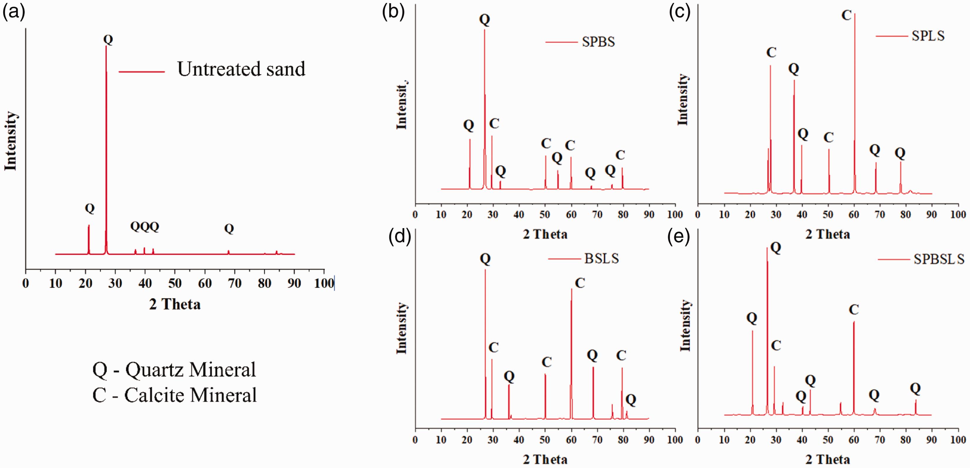
XRD spectra of untreated sand and biocemented sands through hybrid bacteria-induced calcite precipitation.
To quantify the extent of biocementation, the amount of calcite precipitation was determined in the biocemented sand samples using calcimeter, as shown in Figure 6. The results show an almost similar amount of calcite precipitation in all of the prepared biotreated samples. However, the shape and size of calcite crystals are different in all combinations which have been described in the following section. The similarity in calcite content was due to the presence of highly active strain, either SP or LS, in all combinations. The maximum calcite content was observed in SPLS mixture treated specimens in which both highly urease producing strains are augmented. The control samples (without bacteria) showed only 1% calcite in unbonded form, which may be due to the continuous injection of cementation solutions. These results demonstrate that the calcite precipitation occurred because of the presence of urease. The calcite content results showed the effective application of all bacterial mixtures tested in this study for hybridized activity.
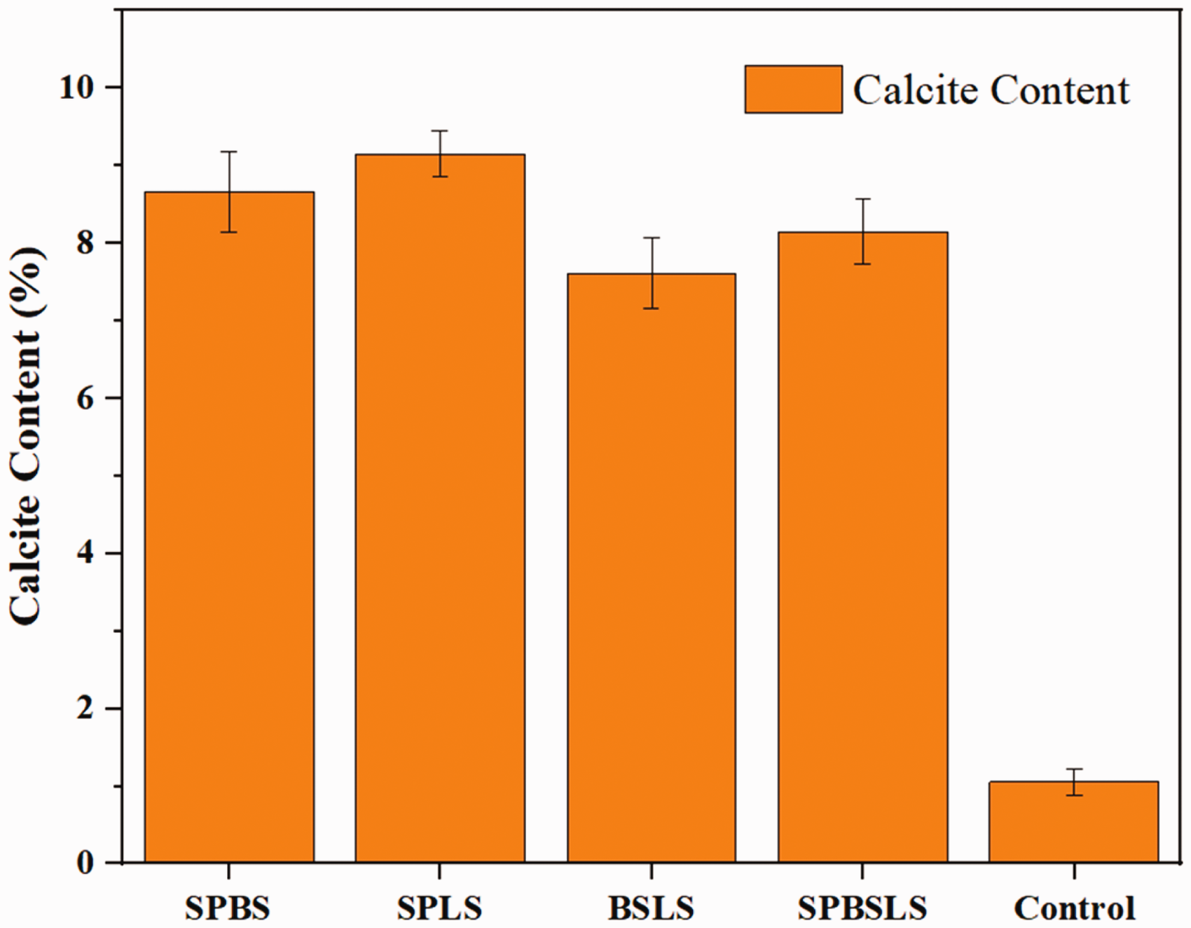
Calcite content of biocemented sands.
Effect of different hybrid bacteria activity on calcite crystals
SEM images were used to examine the calcite crystals present in the untreated and biotreated sands. Figure 7(a) shows the SEM image taken at 600 × magnification to capture the discrete grains of silica sand and reveals that the discrete particles of untreated sand do not contain any calcite crystals. Whereas, Figure 7(b) to (e) shows the presence of calcite crystals in biocemented sands. SEM images were taken at a similar magnification of 2500 × discern the calcite crystals under different biotreatment conditions. Interestingly, the presence of microbial beds can also be seen in Figure 7(b) and (c). These microbial beds were found in 1–5 µm size and appeared on the calcite crystal surfaces in the form of hollow cylindrical spaces. The large size of crystals was observed in Figure 7(c), which may be due to the presence of master bacterium SP for urease production and high spore-forming activity of LS strain. Thus, the hybrid activity of SPLS mixture resulted in the growth of large size crystals due to high urease production. The variations in the crystal sizes are related to the competition of growth of already formed crystals and new crystal formations. The generation of new crystal and the growth of old crystal depends on the interplay of bacteria and cementation solution (Gandhi et al., 1995).
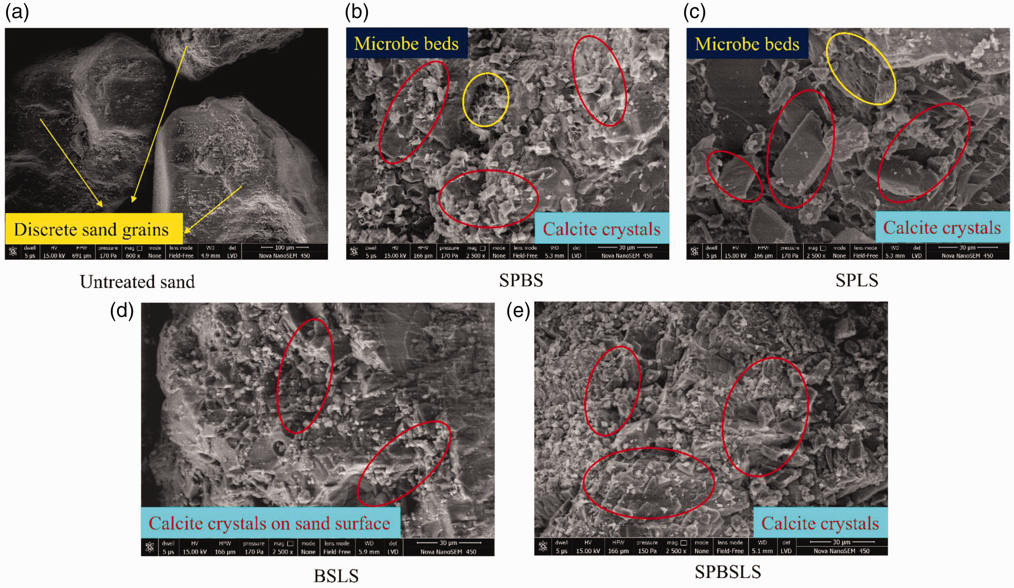
SEM images of untreated sand (magnification – 600×) and hybrid bacteria-induced calcite precipitated biocemented sand (magnification – 2500×).
The microstructural variation and morphology of crystals due to single strain bioaugmentation was analyzed in the previous study (Sharma et al., 2019). It was found that BS resulted in a lesser amount of calcite precipitation than SP and LS strains. The SP strain is widely known as a master bacterium for urease production and generates calcite precipitation for biocementation in sands. The LS strain showed higher calcite content due to its high spore-forming and urease producing activity. Hence, in the present study, it can be interpreted that the SPBS hybrid showed crystal formation and calcite precipitation due to the SP strain dominating properties. The SPLS hybrid resulted in a maximum amount of calcite precipitation as both the strains are highly active in calcite production. The SPLS hybrid also resulted in a large size of calcite crystals. The hybrid BSLS also resulted in lesser precipitation as only one, i.e., LS strain, is dominating. The SPBSLS hybrid relatively smaller size of crystals than the SPLS hybrid. This may be because of the presence of BS strain. The crystal formation majorly depends on the interplay of bacteria strains when the mixed combinations were inoculated. The common urease production affects the size of crystals, which directly influence the strength of biocemented sand. Thus, the SPLS hybrid was found effective in terms of large size crystal production, which can be used for strength enhancement of sand.
Chemical bond formations in calcite precipitated sand
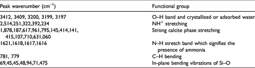
The FTIR was used to assess chemical bond formations under different tested hybrid bacteria conditions in this study, and the results are shown in Figure 8. The vibration bands indicate the presence of minerals of quartz (Si–O) and calcite (C–O). The existence of adsorbed water (O–H) and ammonia (N–H) stretches has been observed (Cardoso et al., 2018; Senvaitiene et al., 2007). As presented in Figure 8 and Table 4, the bands of O–H, N–H, C–O, C–H, and Si–O can be identified in all spectra. The existence of C–O and N–H stretches signifies the formation of calcite and generation of ammonium by-product as a result of the effective application of the MICP process.
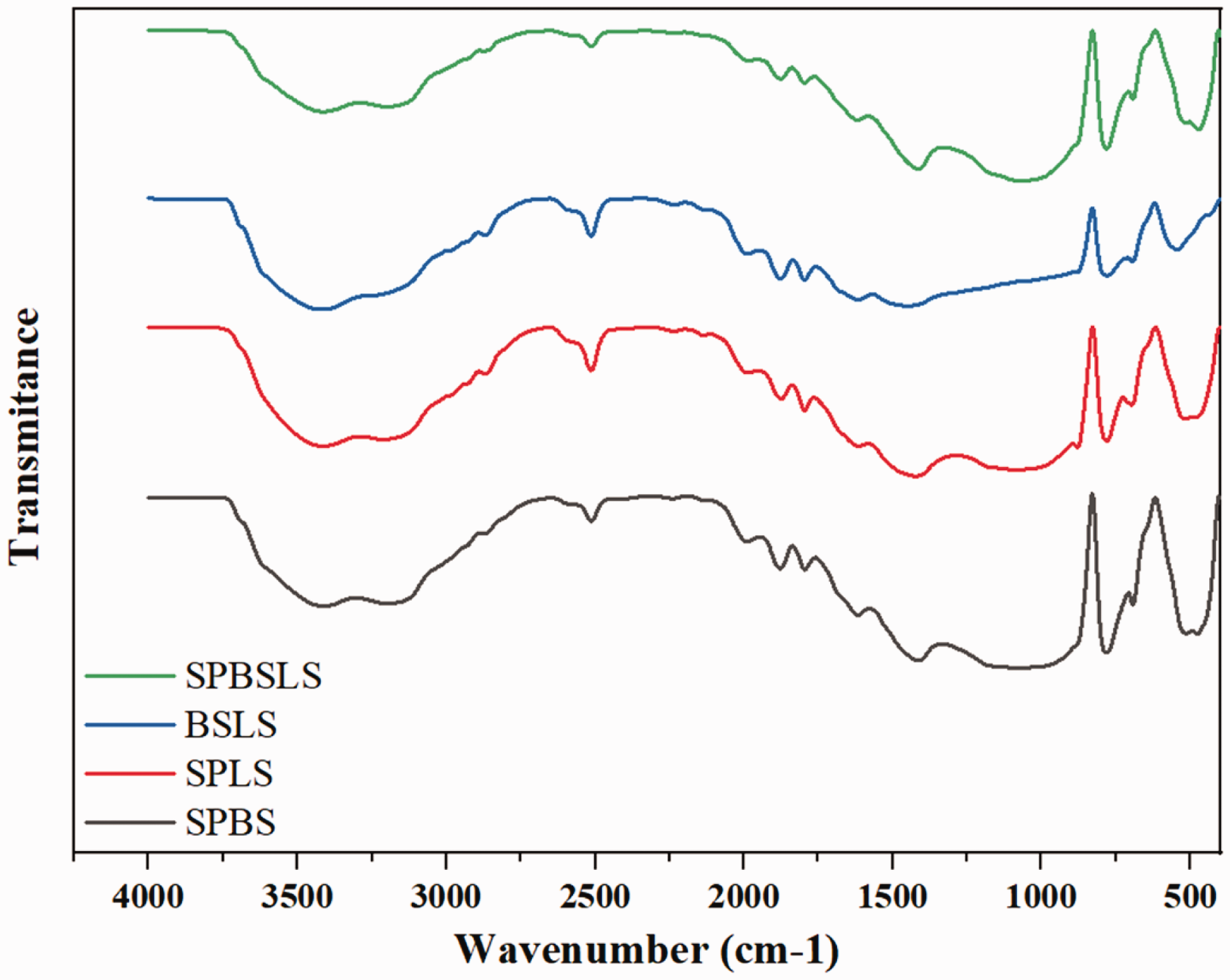
FTIR spectra of biocemented sand under different hybrid bacteria conditions after 14 days of treatment.
IR bands characterization of biocemented sand using FTIR.
Effect of different biotreatment conditions on calcite content, coefficient of permeability, UCS, and STS
The tube sample testing results revealed that the hybrid bacterial conditions induced calcite precipitation for different treatment durations up to 14 days. Thus, if any of the tested combinations present in sand, then the biostimulation alone can be resorted. It should be mentioned here that the non-pathogenicity of bacteria strains was explored extensively in the published studies. For example, Farrar (1963) demonstrated the Genus Bacillus group could be pathogenic, and Bacillus subtilis can cause serious infections in the human body, leading to death. Based on these considerations, the use of Bacillus subtilis was for biocementation applications may not be prudent. Hence, the hybrid bacteria conditions that are considered safe for practical applications were considered in the macro-scale treatment for preparing cylindrical samples for testing for engineering properties, specifically coefficient of permeability, UCS, STS, and stress-strain response.
The top, middle, and bottom layers of the biotreated cylindrical samples were tested to investigate the spatial distribution of calcite content and to ensure the uniformity in calcite precipitation throughout the depth. Figure 9 shows the calcite content variations in biocemented specimens treated with different treatment cycles and cementation solution pore volumes. These results indicate that calcite precipitation occurs uniformly throughout all biotreated specimens except “48 Hyb 0.75/0.5PV”. The longer duration of treatment cycle with lesser pore volume of cemented solution resulted in non-uniform precipitation. Due to this reason, the samples were not formed in cylindrical specimens. This is an important observation as the calcite content uniformity is the major challenge of the MICP technique. As shown in Figure 9, the calcite content of biocemented specimen was found almost similar in each layer with little variation from the top to the bottom layer. The calcite content uniformity shows effective growth of bacterial hybrid, the concentration of cementation solution, and injection (stop-flow) technique. The percentage of calcite content decreases with the increase in the duration of treatment cycle and PV reduction of cementation solution. The calcite content values were similar to those reported in published studies (Mahawish et al., 2018; Sharma et al., 2021b).
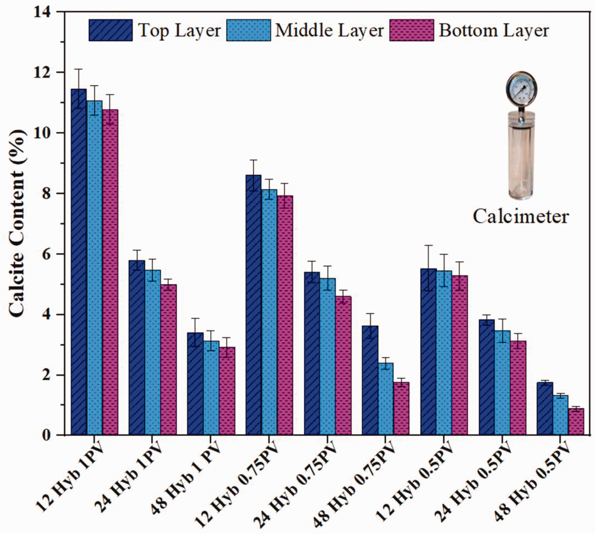
Three-layer calcite content variation with different biotreatment conditions.
The reduction in coefficient of permeability for different treatment periods and biotreatment conditions is shown in Figure 10. The percentage decrease in coefficient of permeability with respect to untreated sand is mentioned at the top of each bar signifying the duration and type of treatment combination. The permeability testing was performed within the UCS and STS molds after the 6th, 12th, and 18th of treatment. While performing the experiments, it has been observed that similar combination-treated UCS and STS specimens resulted in the same coefficient of permeability, demonstrating the reproducibility of the test results. Thus, the average coefficient of permeability values of these experiments was used for analysis. The decrease in coefficient of permeability with increasing treatment time was achieved due to higher amounts of calcite crystal formation between the sand particles. The continuous application of cementation solution resulted in reduction of coefficient of permeability and porosity. The calcite crystal generation on and between sand particles results in reduced pores and tortuous flow of cementation media (Cheng et al., 2014).
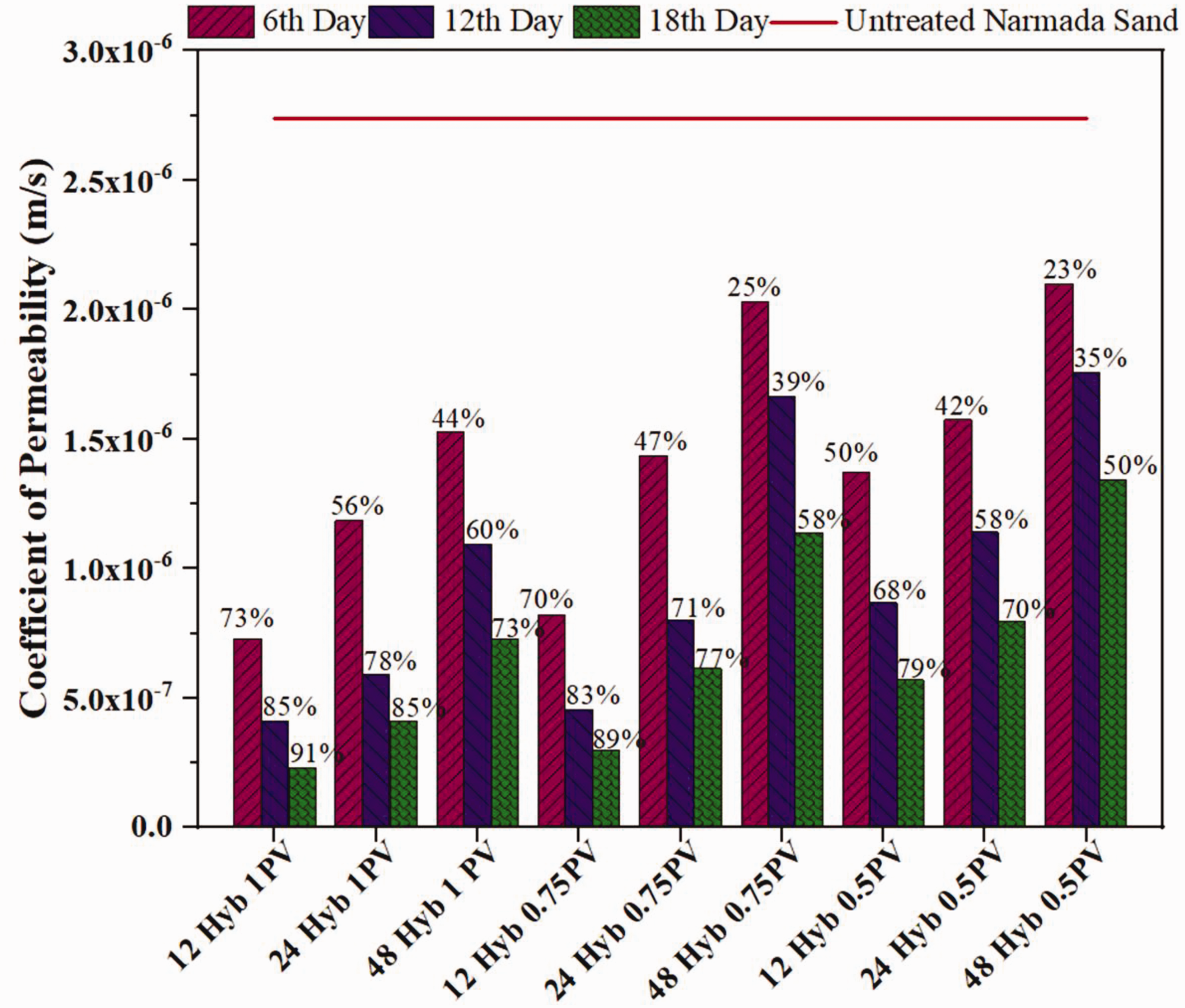
Comparison of coefficient of permeability of untreated and biocemented sands along with the percentage reduction in coefficient of permeability with respect to untreated sand.
The reduction of coefficient of permeability with the average calcite content after 18 days of biotreatment is shown in Figure 11. The decrease in coefficient of permeability was observed to increase with the increase in calcite content. It can be interpreted from Figures 10 and 11 that the minimum reduction in coefficient of permeability was observed in “48 Hyb 0.75/0.5 PV” specimens with the increase in treatment duration. The amount of average calcite content was less than 2.5% in these specimens. The major reason for lesser reduction in coefficient of permeability and minimum calcite content (after 18 days) was due to the longer treatment cycle and lesser amount of cementation solution pore volume. The maximum reduction in coefficient of permeability was observed in “12 Hyb 1PV” with the increase in number of days of treatment. The continuous cementation solution injection of 1 PV for 12-h treatment cycle resulted in 91% coefficient of permeability reduction with 11.11% calcite content after 18 days of treatment (Figure 11). This shows that the amount and frequency of cementation solution injection significantly affect the coefficient of permeability reduction. It is elucidated from Figure 10 that 12- and 24-h treatment cycles with all pore volumes combinations show significant reduction in coefficient of permeability. The specimen “24 Hyb 0.5PV” showed 42, 58, and 70% reduction in coefficient of permeability after 6th, 12th, and 18th day of treatment, respectively. This is an important observation that 42% coefficient of permeability reduction can be significant enough to mitigate liquefaction (a phenomenon that occurs during earthquakes). The 42% reduction in coefficient of permeability shows formation of calcite crystals between and on the surfaces of sand grains. The precipitated calcite reduces the void spaces at granular level which in turn decreases the excess pore pressure generation and results in improvement of liquefaction resistance (Montoya et al., 2012). Even only 1% calcite content in MICP treated sand can increase the liquefaction resistance up to twice than untreated sand (Simatupang and Okamura, 2017). Hence, for only liquefaction mitigation, six days of treatment with 24-h treatment cycle and 0.5 PV cementation solution was found sufficient. This combination can reduce the cost up to 12 times if the treatment is done for six days and four times if the treatment is continued up to 18 days. The decrease in coefficient of permeability was observed in line with the previous research studies (Ivanov et al., 2010; Proto et al., 2016). A reasonable coefficient of permeability retention is advantageous after biotreatment, which is useful in the case of additional treatment cycles for further improvement of engineering properties, including liquefaction resistance (Whiffin et al., 2007).
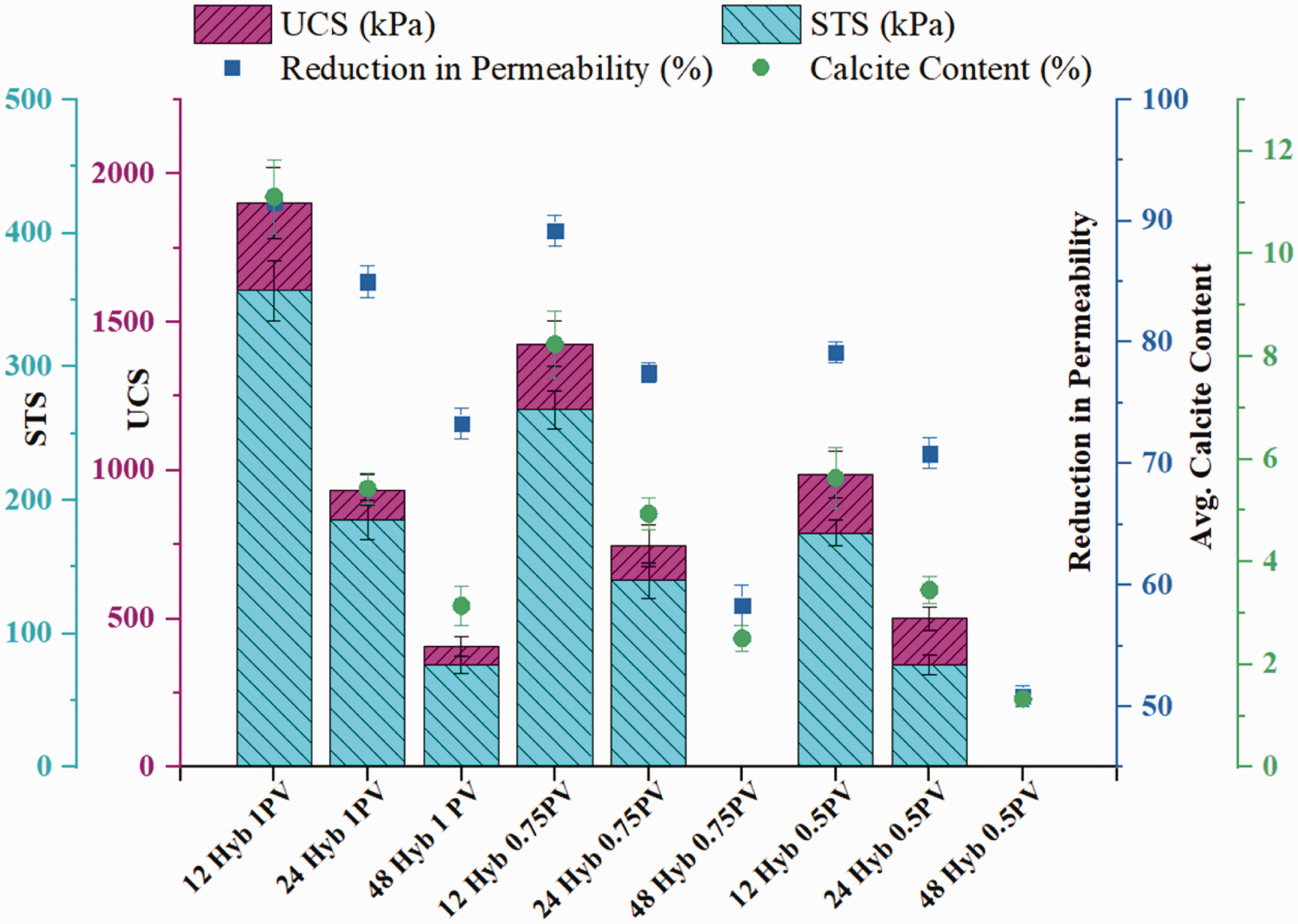
Effect of various biotreatment conditions on calcite content and engineering properties of sand after 18 days of treatment.
Recently, Sharma et al. (2021a) demonstrated that crystal formation and coefficient of permeability reduction depend on various biogeochemical factors. The type of soil, bacteria strain, cell density of bacteria, concentration of cementation solution, treatment cycle, duration of treatment, temperature, and pH affect the biocementation process. The pH of cementation solution was found between 8.5 and 9 in the present study, which lies in the active pH range of 8–9.5 (Van Paassen, 2009). Thus, the pH values signify the successful completion of biogeochemical reactions and precipitation of calcite. On the other hand, the average minimum and maximum temperature range varied from 8 to 40°C during both biotreatments. Hence, the formation of calcite crystals and successful application of MICP technique shows the robust nature of bacterial hybrids to survive in the varied temperature ranges. The calcite content affects the UCS and STS of biocemented sand. The UCS and STS variations with different biotreatment conditions and average calcite contents are shown in Figure 11. While measuring the calcite content for all UCS and STS specimens, the calcite content was found almost similar in identically treated samples, demonstrating repeatability of the test results. The results show that higher calcite content results in higher strength. The specimen “12 Hyb 1PV” showed maximum UCS and STS values of 1902.7 kPa and 356.7 kPa, respectively, with 11.11% calcite content. The specimens “48 Hyb 0.75/0.5PV” were not formed in cylindrical specimens due to less calcite content; therefore, the UCS and STS tests could not be performed on these specimens. Similar to permeability results, the 12- and 24-h treatment cycles resulted in significant increase in strength. In MICP method, the main factor which affects the economy of the whole treatment are cementation solution components. In case of “24 Hyb 0.5PV” combination, only one-fourth of cementation solution pore volume is provided in 18 days as compared to “12 Hyb 1PV”. Thus, the sample combination “24 Hyb 0.5PV” can be used for large-scale applications for cost reduction up to 4 times as compared to “12 Hyb 1PV” treatment combination. Though strength was lesser in “24 Hyb 0.5PV” than “12 Hyb 1PV”, but the strength and calcite precipitation were significant enough to mitigate liquefaction. The achieved strength in “24 Hyb 0.5PV” is higher at similar calcite content as compared to other studies (Rowshanbakht et al., 2016). It was observed that UCS and STS values at similar calcite content showed direct relation. The STS value was in the range of 0.176–0.219 times UCS value. A similar relationship was also observed by Liu et al. (2018, 2019). Overall, the strength enhancement and reduction in coefficient of permeability effectively substantiate the use of bacterial hybrids and treatment strategies for liquefaction mitigation in sands.
Ultrasonic particle velocity (UPV) or shear wave velocity
Figure 12 shows the UPV or shear wave velocity variations with different biotreatment conditions. Typically, the shear wave velocity of untreated, poorly graded sand lies in the range of 149–303 m/s under various confining pressures from 50 to 900 kPa (Riveros and Sadrekarimi, 2020). The results of UPV are in confirmation with calcite precipitation, UCS, and STS variation. The maximum UPV was observed in “12 Hyb 1PV” sample as 2408 m/s with 11.11% calcite precipitation. The minimum UPV, 953 m/s, was measured in “48 Hyb 1PV” with 3.14% calcite. Saxena et al. (1988) demonstrated that the soil with shear wave velocity more than 167 m/s is liquefaction resistant. Hence, even the minimum precipitated sample with uniformity in calcite content is resistant to liquefaction. The significant UPV of 1121 m/s was observed in “24 Hyb 0.5PV”, which is preferred for large scale applications for cost reduction. The shear wave velocities of biocemented sand are nearly similar to the shear wave velocities of sandstone (Zhao et al., 2018). The UPV measurements showed heavily cemented specimens with rock and hard rock categories of specimens as per the National Earthquake Hazards Reduction Program (NEHRP) (2003). The shear wave velocity range 760 < vs ≤ 1500 m/s signifies heavily cemented rock, NEHRP site class B. The shear wave velocity of more than 1500 m/s shows heavily cemented hard rock, NEHRP site class A. The site class of each specimen is shown in Figure 12. This shows the rock-type behavior of biocemented sand.
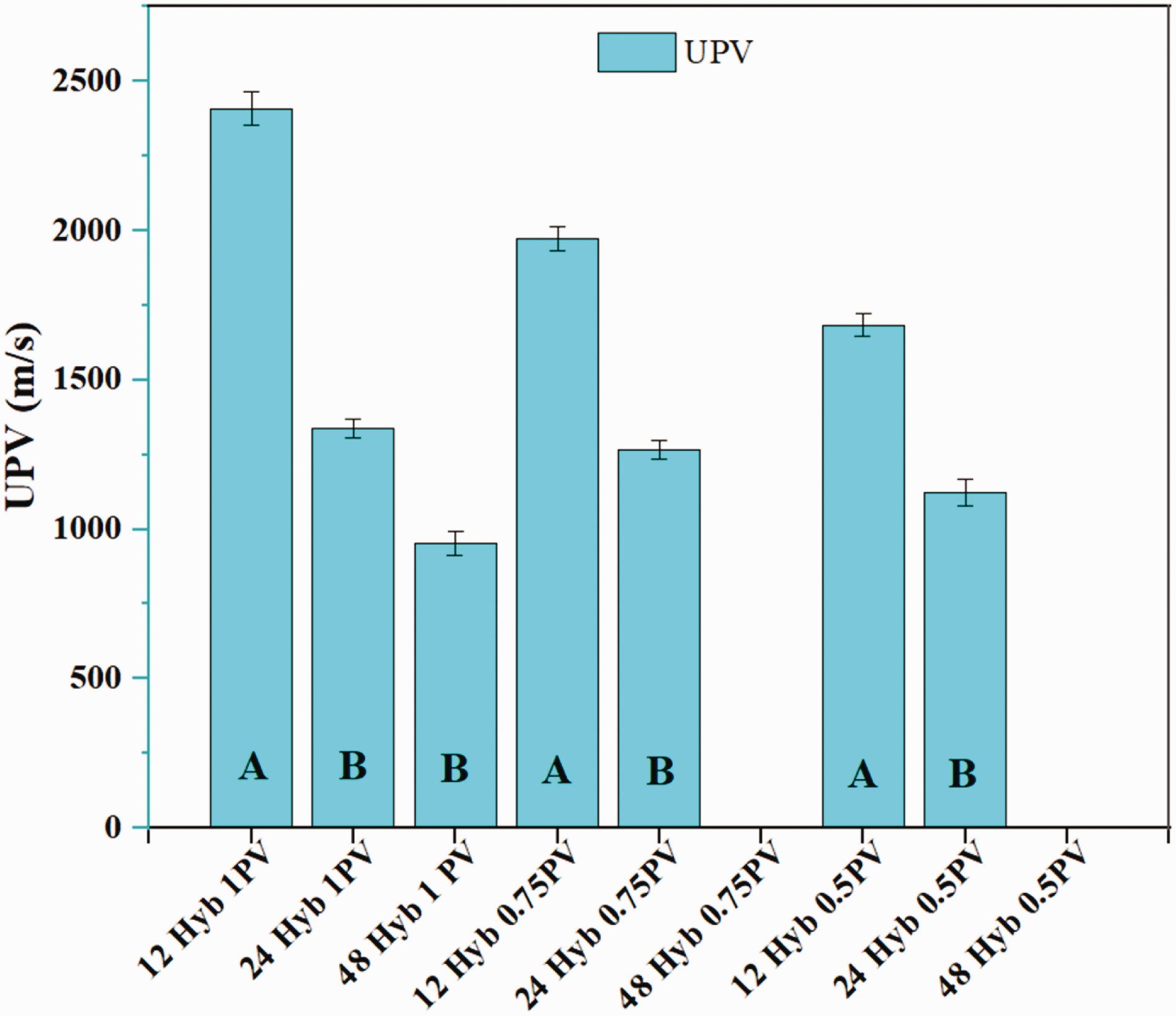
UPV variations in biocemented specimens treated with different treatment cycles and cementation solution pore volumes.
Stress-strain and pore pressure responses
The specimens “12 Hyb 1PV” and “24 Hyb 1PV” was selected according to UPV variations and rock type behavior. All the samples were majorly lying in NEHRP site class A and B. Hence, to understand the stress-strain behavior of site class A and B, the samples “12 Hyb 1PV” and “24 Hyb 1PV” were selected, respectively. The typical stress-strain response (deviatoric stress versus axial strain) and pore pressure response for untreated and selected biocemented specimens based on the CU triaxial tests conducted under the same initial effective confining pressure of 100 kPa, are shown in Figure 13(a) and (b). The triaxial test setup is shown in Figure 13(c). It can be seen from Figure 13(a) that the untreated dense sand specimen showed strain hardening; however, both biocemented specimens showed brittle behavior and then strain-softening behavior. The biocemented sand showed the propensity of strain-softening with the increase in treatment cycle frequency and calcite content consistent with Montoya and DeJong (2015). The deviatoric stress increases in biocemented sands with the increase in axial strain until the peak stress is attained; after that, the strain-softening occurs because of progressive breakage of cementitious bonds. The gradual strain softening is behavior is due to the confining pressure, which shows resistance to dilation. The peak stresses reached at relatively low strains, and then decrease in stress response signifies the brittle behavior of biocemented specimens. The behavior of highly precipitated sample “12 Hyb 1PV” with 11.11% calcite content showed similar trends with Cui et al. (2017). The stress-strain behavior of biocemented sand is consistent with the reported results on artificially cemented sands (Reddy and Saxena, 1993; Saxena et al., 1988a).
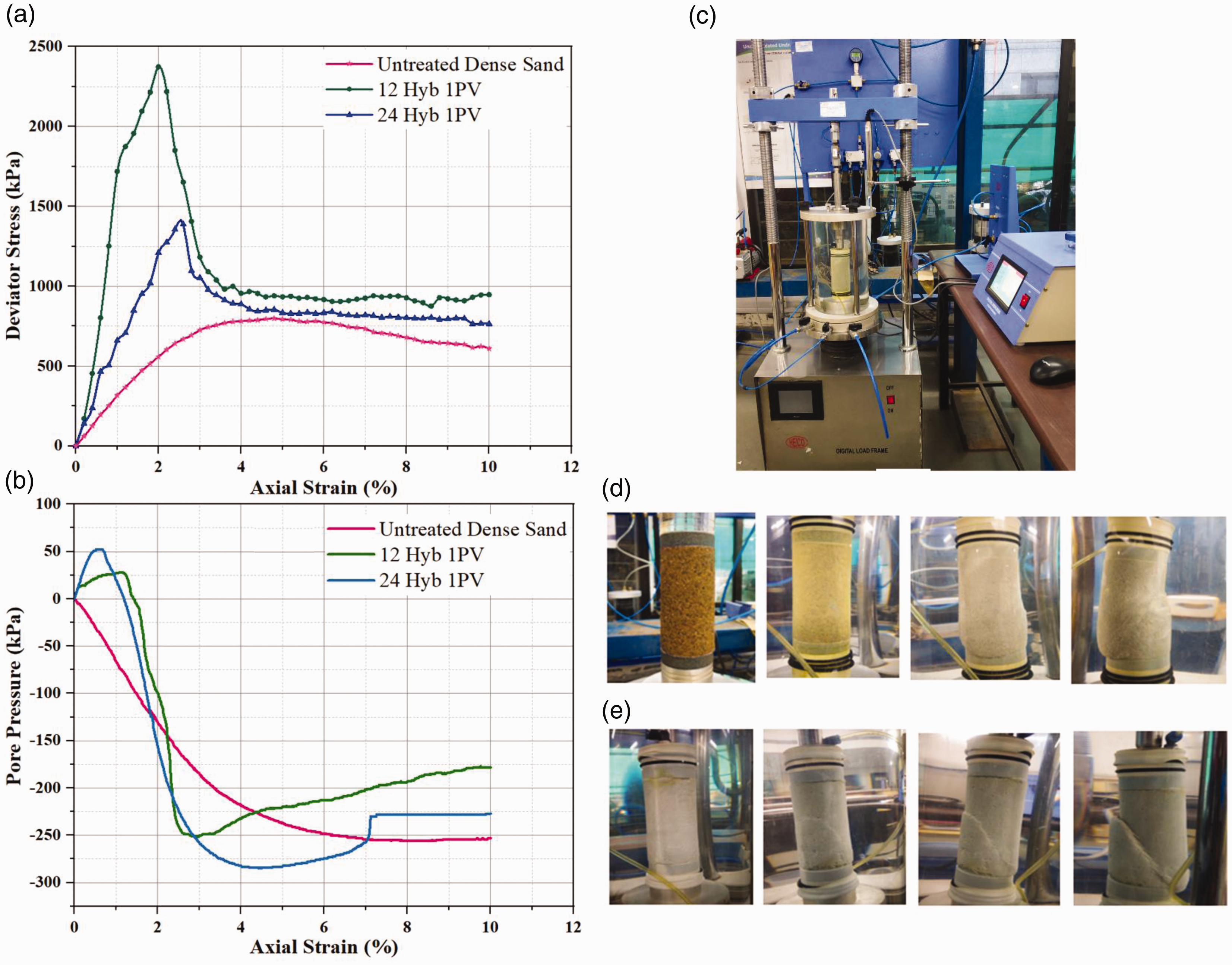
(a) Stress-strain behavior; (b) pore pressure responses of untreated dense sand and biocemented sands; (c) triaxial testing setup; and the failure patterns based on triaxial CU tests of (d) untreated, and (e) biotreated specimens (showing shear failure propagation).
DeJong et al. (2010) demonstrated the bond breakage and damage mechanism of biocemented sands due to loading/shearing. The cracks may occur between the precipitated calcite crystals and sand surface or within the precipitated calcite crystals because of compression, tension, and shear loading. Cil et al. (2017) and Zhao et al. (2015) elaborated on the particle crushing of granular soils under compression loading. However, the grain crushing of sand is reduced due to the presence of calcite crystals and the improvement of bond strength after MICP treatment. The calcite precipitation aid to restrain grain breakage through the following mechanisms: 1) Calcite formation along the sand grain surface increases the effective diameter of the particle, hence requires higher energy to break or crush the grain during loading; 2) The bonded calcite crystals between adjacent sand grains, debonded during loading and dissipates the energy which might cleave the grains in the absence of cementation; and 3) The debonded calcite crystals remains in the pore spaces and decreases the particle contact force magnitudes through the effective distribution of force chains by cushioning effect (Xiao et al., 2020). Thus, the failure mode observation reveals bulging in the untreated sand sample (Figure 13(d)), and due to the restrain in grain breakage, the biocemented sands fail in shear (Figure 13(e)). The pore pressure responses of dense untreated sand and biocemented samples are shown in Figure 13(b). The untreated specimen showed pure dilative behavior. The biocemented specimens initially showed the contractive behavior, which may be due to the rearrangement of particles according to shear deformation. The dilative response of biocemented specimens was observed at strains at which peak stresses occurred.
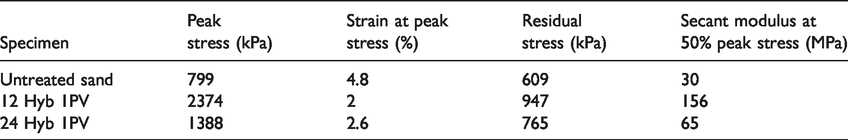
The details of peak stress, strain to reach the peak stress, residual stress, and secant modulus at 50% peak stress for untreated and biotreated specimens are summarised in Table 5. The higher peak stress was found at, the lesser strain in biocemented samples than the untreated dense sand specimen. The peak strength increases with the increase in calcite content of biocemented sand. The residual stresses in biocemented samples were higher than the untreated sand. The residual strength increase, maybe because of the calcite crystal formation between sand grains. Thus, increase in sand grain roughness and cracking of calcite minerals in fine forms resulted in increase of residual strength. The secant modulus was calculated at 50% peak stress (E50). The maximum E50 of 156 MPa was achieved in “12 Hyb 1PV” with 11.11% calcite content. The values of E50 of untreated and biotreated sand were found in line with Nafisi et al. (2020a, 2020b). This signifies the effective application of hybrid of SPLS mixtures. These limited studies demonstrate the significant differences in the stress-strain response of biocemented sands, and a detailed investigation of undrained and drained stress-strain and strength behavior of biocemented sands is being undertaken by the authors.
Comparison of CU triaxial test results at 100 kPa confining pressure for untreated and biotreated sands.
Durability (freeze-thaw cycles)
The durability of biocemented sands was explored by analyzing the effect of FT cycles on strength characteristics. Figure 14 shows the decrease in strength of biotreated sands with the increase in FT cycles. The similar linear relationship was observed in UCS and STS specimens after similar number of FT cycles. The results showed that the strength reduction was less than 5% after 5 FT cycles and 10% after 10 FT cycles in all biotreatment combinations. The less reduction in strength was due to the coefficient of permeability retention of biocemented specimens, which provides access to water for instant mass transfer. The strength reduction of 17–21% and 35–38% was observed after 15 and 20 FT cycles, respectively, in “12 Hyb 1/0.75.0.5 PV” and “24 Hyb 1PV”. This may be due to the high calcite content, which bonded the sand grains together with maintaining the coefficient of permeability. The specimens “24 Hyb 0.75/0.5 PV” showed reduction in strength in the range of 23–27% and 39–43% after 15 and 20 FT cycles, respectively. The strength reduction was higher as the amount of calcite content was less in these specimens.
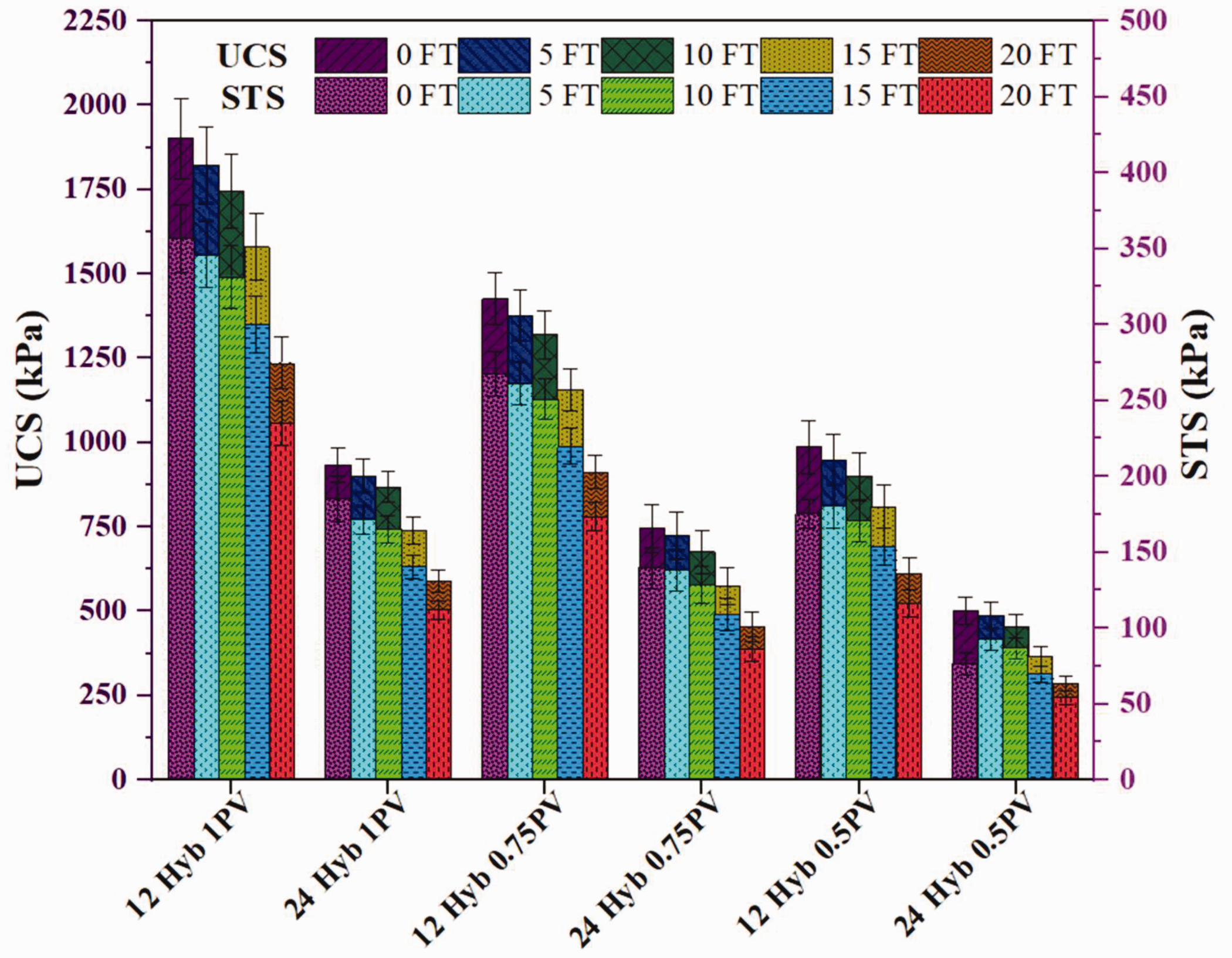
Effect of FT cycles on UCS and STS of biocemented sands treated under different conditions.
The major reason for the reduction in strength of all samples was the generation of microcracks due to continuous FT cycles. The freezing converts the pore water from liquid state to solid-state, and due to the increase in volume, ice exerts tensile stresses on the contact points of sand and calcite. These tensile stresses generate the microcracks, which cause the reduction in strength (Cheng et al., 2017; Liu et al., 2019). The less precipitated specimen among all the combinations, i.e., “24 Hyb 0.5 PV” retains 57% of strength after 20 FT cycles. This signifies the effectiveness of treatment using SPLS hybrid and durability of biocemented specimens.
The influence of FT cycles was also assessed by measuring the UPV of biocemented specimens. The UPV of biotreated samples decreased with the increase in FT cycles, as shown in Figure 15. The UPV reduction was observed in the range of 16–18%, 27–31%, 43–46%, and 59–63% after 5, 10, 15, and 20 FT cycles, respectively, in “12 Hyb 1/0.75.0.5 PV,” and “24 Hyb 1PV” specimens. The samples “24 Hyb 0.75/0.5 PV” showed 19–21%, 31–32%, 47–48%, and 65–67% reduction in UPV after 51,01,520 FT cycles, respectively. The high calcite precipitated samples showed lesser reduction in UPV as compared to less precipitated samples. The UPV reduction was because of the generation of microcracks between the sand-calcite contact points as the ice exerted tensile stresses during freezing. The less precipitated specimen “24 Hyb 0.5PV” showed UPV value as 435 m/s after 20 FT cycles. This signifies the liquefaction resistance of the specimen even after 20 FT actions. Hence, the biocemented sand for all biotreatment combination was found durable and liquefaction resistant even after FT actions.
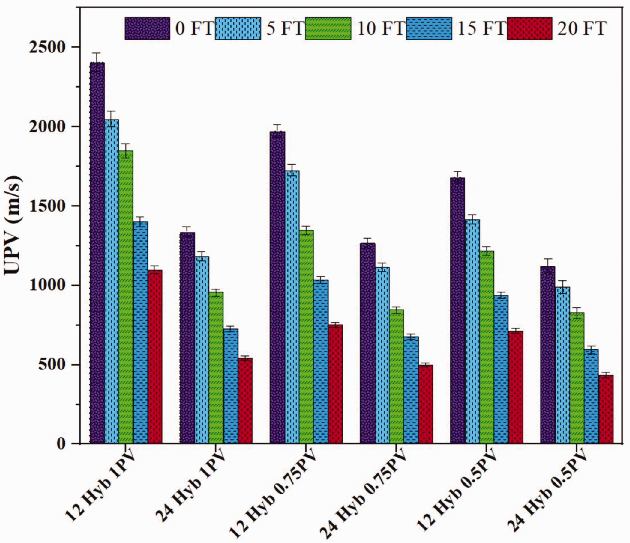
Variation in UPV of biocemented sands due to the increase in FT cycles.
Conclusions
The capability of bacterial hybrids for MICP methods was investigated on poorly graded, liquefiable sand. The microscale and macroscale investigations were carried out on calcite precipitation and improvement in engineering properties. Initially, the treatment was conducted in tubes with different bacterial mixtures. The biocemented sand was analyzed for calcite content, SEM, XRD, and FTIR after 14 days of treatment. Further, the treatment was carried out in PVC pipes to prepare cylindrical specimens. The sand was biotreated with a single bacterial mixture (SPLS), 12- and 24-h treatment cycles, and three different pore volumes of cementation solution up to 18 days. The later treatment was conducted in non-sterile and environmentally uncontrolled conditions. The coefficient of permeability was measured after 6th, 12th, and 18th of biotreatment. The biocemented samples were tested for calcite content uniformity, UCS, STS, UPV, and stress-strain response. The effects of freeze-thaw cycles (5, 10, 15, and 20) were also analyzed based on UCS, STS, and UPV tests. The following conclusions are drawn from this study:
The bacteria cultivated under a non-sterile environment showed significant optical density, and its application resulted in successful MICP process. The non-sterile and uncontrolled laboratory environment did not influence the biotreatment process. The mixed combination of SP, BS, and LS showed effective metabolic activity as a hybrid and resulted in significant calcite content. The microcharacterization showed the successful generation of hybrid induced calcite precipitation. The uniformity in calcite precipitation was achieved, which signifies the effective hybrid activity and efficiency of cementation solution. The maximum strength and durability were observed in the 12-h treatment cycle, and 1 PV treated specimens augmented with SPLS mixture. However, the 24-h treatment cycle and 0.5 PV cementation solution injected specimens resulted in significant strength improvement and potential for liquefaction mitigation. The biocemented samples were found to be potentially liquefaction resistant with sufficient strength and UPV values even after 20 FT cycles. The treatment combination of 24-h treatment cycle and 0.5 PV of cementation solution can be used for large scale applications to reduce the cost up to four times. The biocemented specimens showed heavily cemented rock-type behavior with maximum UPV value of 2408 m/s, which is similar to sandstone (as per NEHRP 2003). The biocemented specimen exhibits brittle nature until peak followed by strain-softening shear behavior.
Additional investigations are needed to assess the feasibility of applying in large-scale applications in actual field conditions and to establish the guidelines on the implementation of biotreatment.
Footnotes
Acknowledgements
The authors gratefully acknowledge the support of Dr Ajanta Sachan, Associate Professor, IIT Gandhinagar, for allowing the Geotechnical Lab access for triaxial testing. The authors are also thankful to the Ministry of Human Resources Development (MHRD), Government of India, for providing Ph.D. fellowship to the first author.
Declaration of conflicting interests
The author(s) declared no potential conflicts of interest with respect to the research, authorship, and/or publication of this article.
Funding
The author(s) received no financial support for the research, authorship, and/or publication of this article.