This study presents a comprehensive microstructure-sensitive investigation of deformation and failure in dual-phase Ti-5Al-5Mo-5V-3Cr (Ti-5553) alloy using crystal plasticity finite element methods coupled with experimental characterisation. Material parameters governing elastic–plastic behaviour and damage evolution (void nucleation, growth, and coalescence) were calibrated via inverse modelling using stress–strain data and EBSD-informed microstructures from heat-treated samples. Representative volume elements systematically capture realistic morphologies, including embedded, grain boundary, triple junction, and elongated grain configurations. Simulations explore how stress triaxiality ( = 1/3 to 3), Lode parameter ( = −1 to 1), Burgers orientation relationship (BOR) variants, crystal orientation, phase volume fraction, and phase-boundary geometry govern slip localisation and damage evolution. Key findings reveal stress-state dependent optimal microstructural parameters: (1) at moderate triaxiality ( = 1/3), volume fractions near 10% suppress strain localisation and delay damage onset; (2) under elevated triaxiality ( = 1), lower fractions (∼5%) become more damage-resistant; (3) crystallographic compatibility across interfaces, determined by BOR variant selection and boundary orientation, directly controls interfacial stress concentrations and void nucleation sites; (4) orientation-dependent slip transfer at interfaces is found to be critical, favourable crystal alignments (e.g. 60° rotation of grain) promote homogeneous strain distribution, whereas unfavourable alignments (0°, 30°) localise deformation at boundaries. SEM fractography from tensile-tested samples validates predicted void nucleation and coalescence patterns near fracture surfaces. This work establishes quantitative, mechanistic links between microstructure (phase-morphology, crystallographic relationships, volume fractions) and damage under complex loading states, providing new insights for rational alloy design and process optimisation in high-performance dual-phase titanium aerospace components.
Ti-5Al-5Mo-5V-3Cr (commonly called Ti-5553) is a near- titanium alloy developed for aerospace applications, notably used in Boeing 787 landing gear components as a replacement for the older Ti-10V-2Fe-3Al alloy and A350XWB airframes (Hu et al., 2024; Manda et al., 2024; Qin and Li, 2019; Ramachandiran et al., 2022; Veeck et al., 2004). It offers a superior combination of high strength, fracture toughness, and fatigue resistance compared to the workhorse Ti-6Al-4V (Ti-64) (Veeck et al., 2004). The microstructure of Ti-5553 after processing consists of dual-phase and , and it can be tuned via thermomechanical treatments to optimise properties. Typical heat treatments produce either a bimodal microstructure (primary equiaxed in a matrix, plus fine secondary α precipitates) or a lamellar microstructure (α laths in colony form within prior grains, often called basket-weave; Hu et al., 2024; Qin et al., 2016, 2024). It has been reported that bimodal Ti-5553 alloy exhibits better combination of strength, plasticity, and failure as compared to other bimodal titanium alloys and are therefore used in thick forging components used in aircraft (Cotton et al., 2015; Qin et al., 2022).
Previous studies have highlighted the critical role of manufacturing parameters and thermomechanical processing (TMP) routes in determining material properties. For example, researchers have made efforts to understand the effect of these on microstructure and most importantly their link with the mechanical properties (Cotton et al., 2015; Fanning, 2005; Hendl et al., 2021, 2023; Hicks et al., 2020; Hu et al., 2024; Qin et al., 2024; Sadeghpour et al., 2017; Schwab et al., 2016). Prior studies have investigated the role of interfaces and are increasingly recognised as a critical factor in determining the overall mechanical performance (Cotton et al., 2015; Hendl et al., 2023; Hu et al., 2024). This remains not fully understood and efforts are being made to develop a quantified link between manufacturing process parameters, post-manufacturing thermomechanical treatment, microstructure, and mechanical properties.
Shekhar et al. (2015) examined the microstructural evolution, tensile behaviour, and fracture characteristics of Ti-5553 alloy under different solution treatment and ageing conditions. Results showed that solution treatment refined grain size and, after ageing, produced finer precipitates at lower temperatures and coarser morphologies at higher ones, while solution treatment and ageing gave higher strength but lower ductility. Fractography revealed mixed-mode fractures in -treated samples and dimpled surfaces in -treated samples, with the latter offering the best strength–ductility balance. Qin and Li (2019) performed split Hopkinson bar testing along with SEM and TEM to investigate the dynamic tensile and compressive behaviour of equiaxed, lamellar, and bimodal Ti-5553 alloys. Results showed that equiaxed alloy had the lowest dynamic yield strength with kinking and stress-induced martensite as key mechanisms, while lamellar and bimodal alloys were strengthened by α precipitates but exhibited different damage behaviours, viz. adiabatic shear bands under compression and interfacial micro-voids under tension. The bimodal alloy demonstrated the best balance of strength and ductility at high strain rates, making it most suitable for impact-resistant applications. Sen et al. (2019) investigated the tensile behaviour of Ti-5553 alloy by generating three distinct microstructures: a fully phase and two lamellar structures with different aspect ratios. Mechanical testing showed that the single phase retained high yield strength, lamellar had high strength with no work hardening, and smaller aspect ratios produced higher strength, but lower ductility compared to larger . Ramachandiran et al. (2022) investigated how precipitate morphology affects the mechanical properties of additively manufactured Ti-5553 alloy produced by laser powder-bed fusion. Samples printed at low and high volumetric energy densities were characterised using XCT, EBSD, X-ray diffraction (XRD), OM, tensile and impact testing, and fracture surface analysis. Qin et al. (2022) fabricated a homogeneous bimodal Ti-5553 alloy with prior- grain through TMP, solution treatment, and ageing to study the balance of strength and ductility. Ageing behaviour at 500–700 °C was analysed, showing that 500 °C gave the highest strength (1430 MPa, 9.5% elongation), 620 °C produced moderate strength with stable ductility, while 700 °C enhanced ductility without strengthening. Microstructural analysis revealed that grain boundary precipitates formed more readily than intragranular but did not contribute to strengthening, with alloy properties governed by dislocation density, grain size effects, and the plasticity of grain boundary. Hu et al., (2024) investigated the deformation behaviour of a bimodal Ti-5553 alloy with equiaxed grains, focusing on the role of α/β interfaces in governing localised strain and slip activity. The study presented a qualitative relationship between interface behaviour and deformation response. Qin et al. (2024) investigated enhancing the fracture toughness of high-strength bimodal Ti-5553 alloys through the grain-boundary delamination toughening mechanism. Wang et al. (2025) investigated the room-temperature tensile deformation behaviour of cast Ti-5553 alloy under different heat treatments and its link to the characteristics of precipitated phases. Arohi et al. (2024) compared two TMP routes, viz. 40% forging (TMP-I) and 20% rolling (TMP-II), applied to as cast Ti-5553 alloy to optimise microstructure and mechanical properties. Both methods produced similar bimodal microstructures with improved hardness and tensile behaviour relative to the as cast alloy, with rolling showing slightly lower indentation size effects. Digital image correlation (DIC) revealed that property improvements stemmed from reduced strain localisation, highlighting rolling with lower deformation as an efficient and economical approach for large-scale applications.
Modelling and simulation related research on Ti-5553 is reviewed in the following. Ben Bettaieb et al. (2015) performed experimental studies on fracture in Ti-6Al-4V and two Ti-5553 microstructures, focusing on void nucleation, growth, and coalescence. A damage model was developed in an elastoviscoplastic framework and was validated through simulations of a bolted aircraft engine stator. Mandal et al. (2017) studied the mechanical response of Ti-5553 alloy through uniaxial compression tests conducted at different strain rates and temperatures below and above the transus. A viscoplastic self-consistent model was applied to reproduce the stress–strain behaviour, using both an empirical modified Voce model and a physically based Mechanical Threshold Stress (MTS) model. While the Voce model showed no consistent parameter trends, the MTS model successfully captured deformation across a wide range of conditions and was further validated against similar titanium alloys. Bobbili and Madhu (2019) investigated the dynamic flow behaviour of Ti-5553 alloy under compression at temperatures from 25 °C to 600 °C and strain rates up to 2000/s. A modified crystal plasticity (CP) model combined with the Arrhenius equation was used to capture work hardening, dynamic recovery, strain hardening, and thermal softening. Yang et al. (2025) examined the hot compression behaviour of Ti-55531 alloy at different temperatures (790–940 °C) and strain rates (0.01–1 s−1). A constitutive Arrhenius-type model was developed through linear regression to quantify the relationship between stress, strain rate, and temperature, and a thermal processing map was constructed. Agius et al. (2021) developed a 2D simulation framework to predict both microstructure and bulk properties of additively manufactured metals, focusing on Ti-5553 alloy. The approach integrated phase-field modelling to simulate microstructural evolution with CP modelling to compute stress–strain responses based on the predicted microstructures. Simulations demonstrated how variations in grain size and orientation influence meso- and macro-scale mechanical behaviour, highlighting the framework's potential for digital-twin applications in process optimisation. While our previous studies (Bin Asim et al., 2019, 2022) established the CP framework for deformation and damage modelling in titanium alloys, the present work extends these efforts in several key directions. First, a systematic investigation of stress triaxiality and Lode parameter effects is conducted to quantify their role in microstructure-sensitive damage evolution. Second, the role of interfacial mechanics is analysed in detail through Burger's orientation relationship (BOR) variant families. Third, the combined influence of phase volume fraction and stress state is explored, revealing non-monotonic and stress-state dependent damage trends. These aspects collectively represent a significant advancement beyond prior work, enabling a mechanistic understanding of deformation-damage coupling in dual-phase Ti-5553 alloy.
It is also clear from the above discussion that though prior studies have advanced understanding of Ti-5553 through experimental testing and macroscale modelling, significant gaps remain in linking microstructural features to deformation and especially failure. Experimental investigations have primarily been qualitative, highlighting trends such as the role of interfaces or grain morphology, but without providing quantitative predictions of failure. Meanwhile, modelling efforts have either relied on phenomenological constitutive or damage models at the macroscale or employed CP only to study deformation without considering failure. In contrast, the present work adopts a CP finite element framework capable of capturing both the deformation behaviour and failure processes of bimodal Ti-5553 microstructures generated through forging and related treatments. This provides a mechanistic and microstructure-sensitive modelling of deformation and failure in Ti-5553, bridging the gap between experimental observations and predictive simulations.
CP framework
In the present investigations, a CP framework is employed that accounts for (i) dislocation slip as the primary deformation mechanism, (ii) the dual-phase microstructural morphology, and (iii) the progressive stages of damage evolution, namely nucleation, growth, and coalescence. A summary of the CP model is provided below, with full details of the constitutive formulation and numerical implementation available in (Bin Asim et al., 2019, 2022) and are not repeated here for brevity.
The total deformation gradient is given by
where and are elastic and plastic deformation gradients.
Elastic deformation gradient is a split of elastic stretch, , and a rigid body rotation, , and is given by
Meanwhile, plastic deformation gradient is a function of deformation gradient due to plastic slip (shape change), , and damage (volume change), ,
In terms of velocity gradient,
with a velocity gradient given by
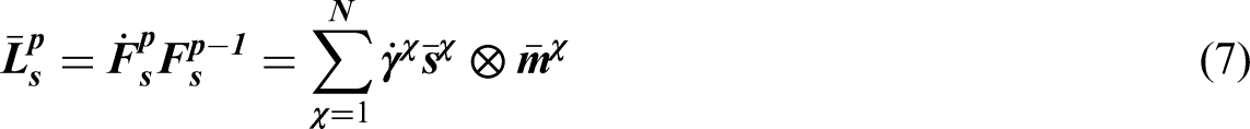
Here is the plastic velocity gradient and is given by
is the velocity gradient due to slip and is given b y
Here and are the unit vectors along the slip direction and normal to the slip plane in the crystal coordinate system, is the shear strain rate due to slip and ⊗ is the outer (dyadic) product.
While is the velocity gradient due to void nucleation and growth and is given by
where is a non-dimensional strain-like quantity and is a function of void nucleation and growth. is a material parameter and is the second-order identity tensor.
Anisotropic elasticity is defined in terms of the second Piola–Kirchhoff stress. Here is the fourth-order stiffness tensor:
where the coefficient is a material parameter, is the resolved shear stress in the slip system , and is the critical resolved shear stress.
The nucleation and growth part is defined as
where is equivalent strain, X the stress triaxiality, and L the Lode parameter. , , , and are material parameters identified through experimental stress–strain curves.
Once reaches a critical value , void coalescence mechanism takes over and is given by
where and are material parameters that control the rate of void coalescence.
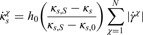
Slip system hardening in equation (10) is defined by
where , , are material parameters.
Materials parameter identification through experiments
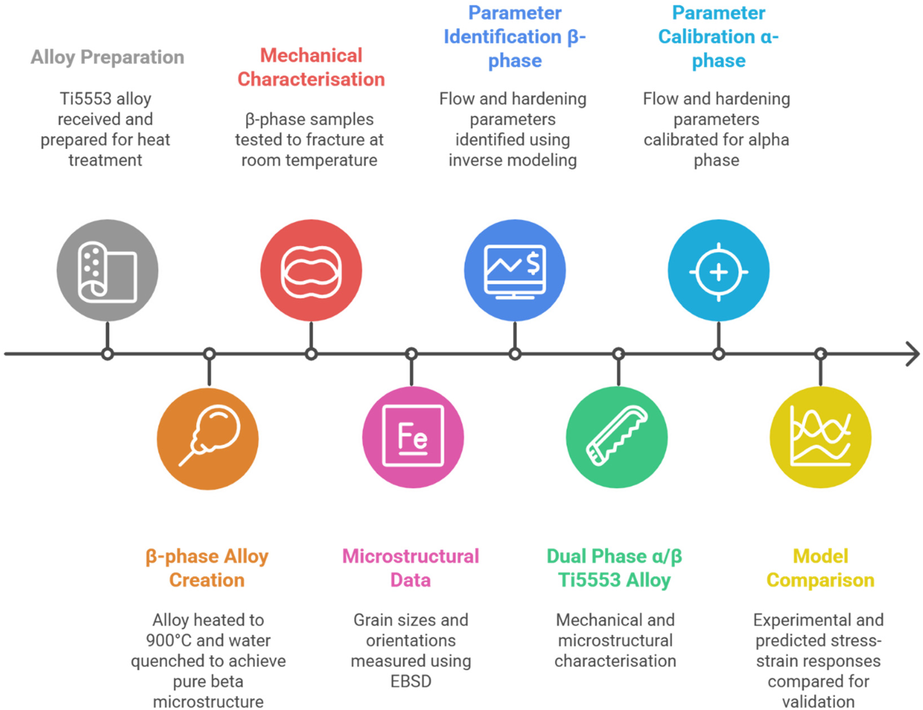
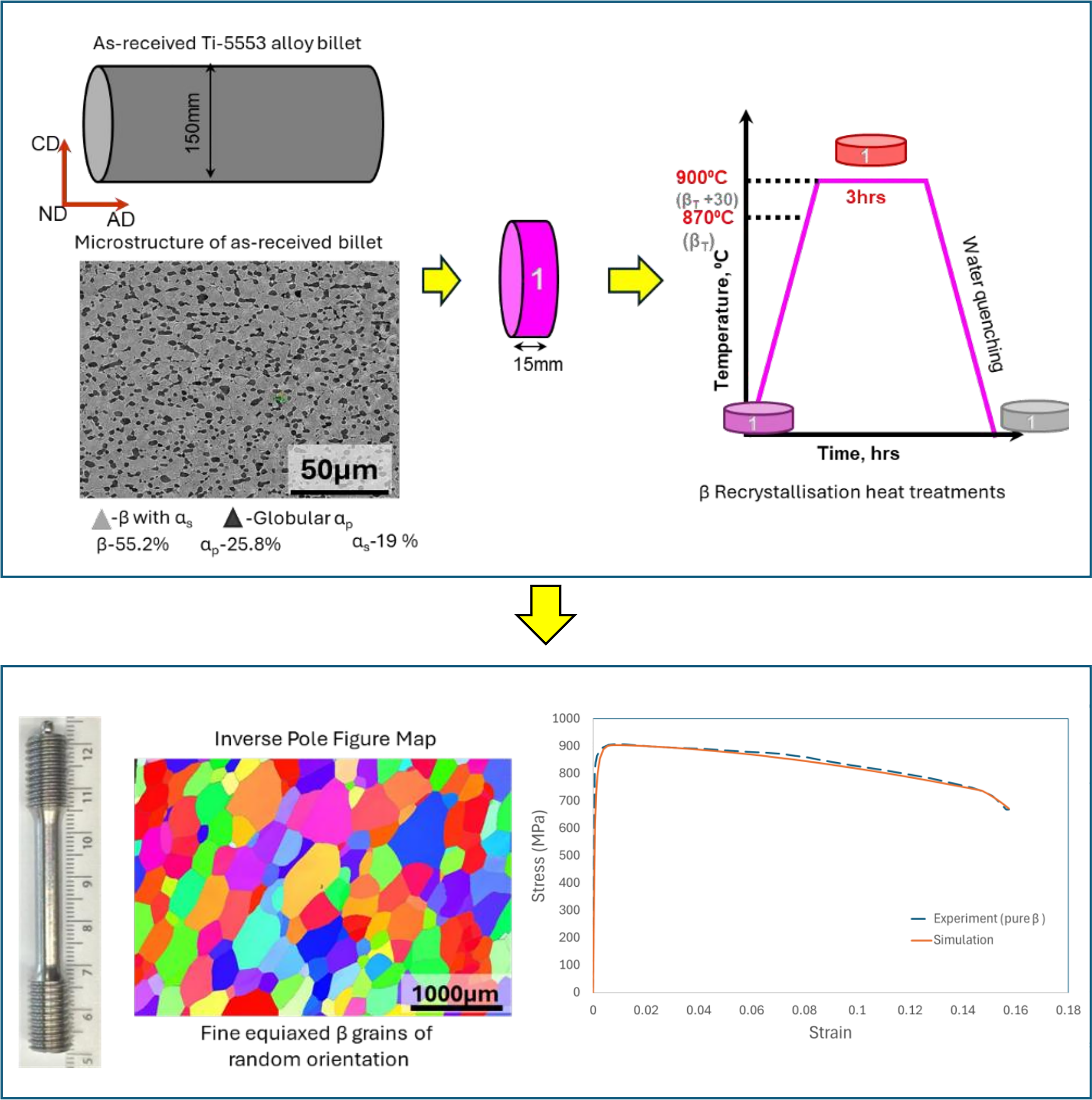
Using a step-by-step inverse modelling approach (see Figure 1), material parameters were identified for dual-phase Ti-5553 alloy. Uniaxial tensile tests were performed to obtain stress–strain behaviour of Ti-5553 alloy with different microstructures. These results were then used to calibrate the material parameters governing the elastic–plastic behaviour along with damage (void) nucleation, growth, and coalescence.
Material parameters identification procedure through experiments.
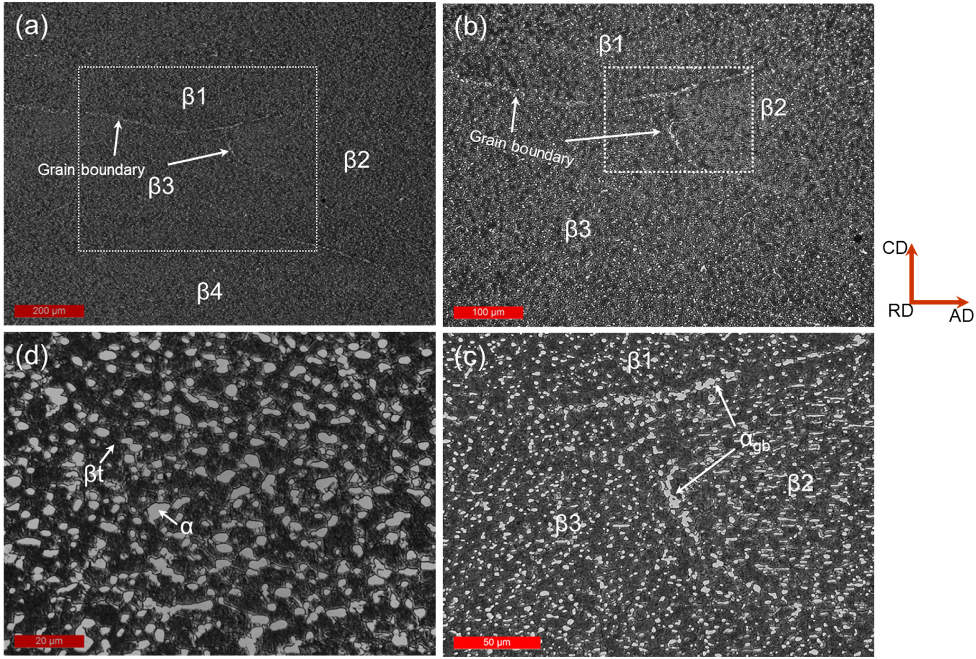
In the first step, material parameters for pure phase were identified. Figure 3 illustrates the experimental procedure used to obtain phase alloy of the Ti-5553. Cylindrical billets (160 mm × 150 mm) were sectioned into discs and subjected to solution treatment at 900 °C ( + 30) for 3 h, followed by water quenching. The as-received microstructure was characterised using optical microscopy (Optical micrographs, Figure 2), revealing a bimodal structure typical of Ti-5553 alloys. XRD analysis confirmed the presence of HCP phase and BCC phase, consistent with prior studies on near- titanium alloys. The as-received microstructure (SEM, Figure 3; top image) revealed primary in a matrix with fine, equiaxed morphology, while the post-treatment EBSD map (Figure 3; bottom left) showed significant coarsening and growth of pure grains. Samples taken for EBSD analysis were mechanically ground and polished followed by electro polishing. A3 electrolyte was used, which contains 600 mL methanol, 360 mL butoxy-ethanol and 60 mL of perchloric acid. The temperature of the electrolyte was 10–15°C. The voltage and flow rate used were 35 V and 15 L/s. Struers LectroPol-5, automatic electrolytic polishing and etching equipment was used for electro-polishing the mechanically polished samples. The acquisition of EBSD scan was carried out using a fully automated HKL-Aztec system interfaced to a FEI Quanta-650 field-emission gun scanning electron microscope, with an accelerating voltage of 25 kV and a 100 µm diameter aperture. HKL Channel 5 software of Oxford instruments was used to process EBSD scan for this study.
Optical microscopy images from as-received Ti-5553 alloy: (a) low magnification image from an area showing microstructure of four pre-existing β grains (β1, β2, β3 and β4), (b) higher magnification image showing the presence of α and transformed β (βt) with in β1, β2 and β3, (c) micrograph showing the thin layer of α precipitated along the boundaries of β grains (αgb) and (d) micrograph from interior of β grain showing the presence of equiaxed primary α (white) and βt (black).
Processing route of Ti alloy billets, showing as-received microstructure (SEM) and post-heat treatment EBSD map after solution treatment at 900 °C and 870 °C for 3 h.
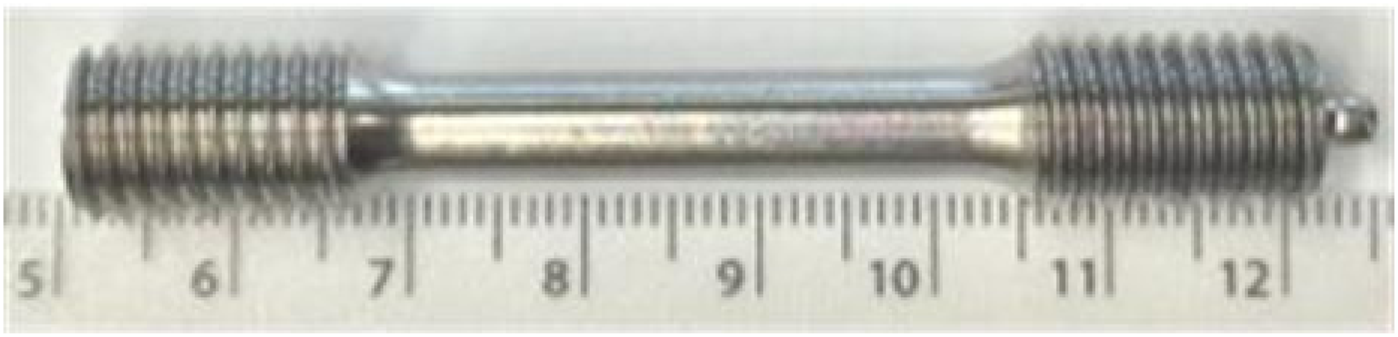
Tensile tests were then performed on these samples (Figure 4) until fracture at a strain rate of 10−3 s−1 at room temperature. Samples were 70 mm in length, 6 mm diameter at gauge section and a gauge length of 24 mm. Three samples per condition were tested and samples were tested up to fracture in all cases. Epsilon extensometers were used to get load–displacement values during the test and were used to derive the true stress–true strain curve for each sample.
The flow curve of samples is shown in Figure 3 (bottom right). EBSD data (grain sizes and orientations) along with true stress/strain curves were used for parameter identification. Through inverse modelling (see Bin Asim et al., 2019, 2022; Siddiq, 2019; Siddiq and Schmauder, 2005, 2006; Siddiq et al., 2008) flow and hardening parameters discussed in the previous section were identified for the pure phase of Ti-5553 alloy. The material parameters were identified using a sequential inverse modelling approach based on experimental stress–strain data and EBSD-informed microstructures. The calibration procedure was carried out in a stepwise manner to ensure robust identification of phase-specific parameters. In the first step, the phase parameters were calibrated using near single-phase microstructures obtained through solution treatment above the transus. This enabled reliable identification of elastic constants, slip system parameters, and hardening behaviour for the phase. A comparison of stress–strain curves between experiment and model is plotted in Figure 3 (bottom right), showing a very good agreement.
In the second step, the phase parameters were identified using dual-phase microstructures (∼79% and ∼21% ). The calibration was performed by iteratively adjusting phase slip and hardening parameters to match the experimentally measured macroscopic stress–strain response, while accounting for load sharing between the phases. In the final step, damage model parameters governing void nucleation, growth, and coalescence were calibrated by matching the onset of softening and failure behaviour observed in the experimental stress–strain curves.
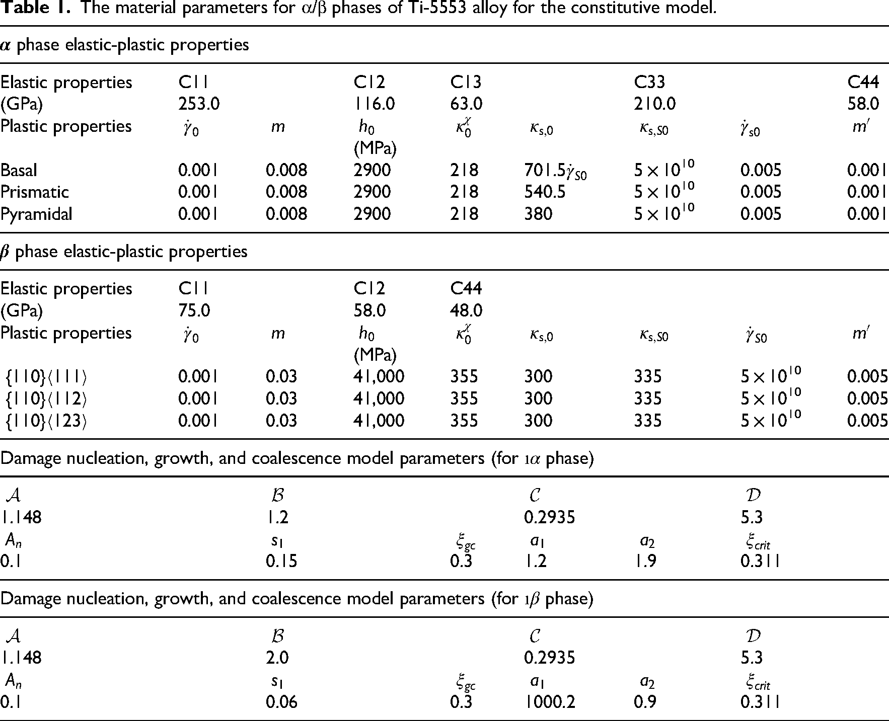
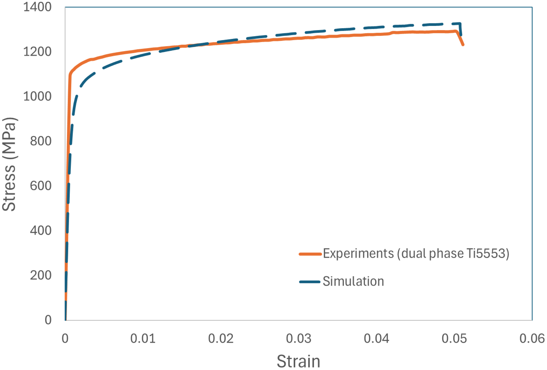
The calibration process involved iterative comparison between CP finite element method (CPFEM) predictions and experimental data, with parameters adjusted to minimise discrepancies in yield strength, strain hardening, and overall stress–strain response. Parameter identification was constrained within physically admissible ranges reported in the literature to ensure stability and avoid non-unique solutions. The procedure ensures consistency between experimentally observed behaviour and simulated response across different microstructural configurations (Bin Asim et al., 2019, 2022). A comparison between the experimental stress–strain response and simulation results using the present constitutive formulation is shown in Figure 5. The identified set of parameters is listed in Table 1.
Tensile test samples of Ti-5553 (pure phase).
The material parameters for α/β phases of Ti-5553 alloy for the constitutive model.
phase elastic-plastic properties
Elastic properties
C11
C12
C13
C33
C44
(GPa)
253.0
116.0
63.0
210.0
58.0
Plastic properties
(MPa)
Basal
0.001
0.008
2900
218
701.5
5 × 10¹⁰
0.005
0.001
Prismatic
0.001
0.008
2900
218
540.5
5 × 10¹⁰
0.005
0.001
Pyramidal
0.001
0.008
2900
218
380
5 × 10¹⁰
0.005
0.001
phase elastic-plastic properties
Elastic properties
C11
C12
C44
(GPa)
75.0
58.0
48.0
Plastic properties
(MPa)
0.001
0.03
41,000
355
300
335
5 × 10¹⁰
0.005
0.001
0.03
41,000
355
300
335
5 × 10¹⁰
0.005
0.001
0.03
41,000
355
300
335
5 × 10¹⁰
0.005
Damage nucleation, growth, and coalescence model parameters (for phase)
1.148
1.2
0.2935
5.3
0.1
0.15
0.3
1.2
1.9
0.311
Damage nucleation, growth, and coalescence model parameters (for phase)
1.148
2.0
0.2935
5.3
0.1
0.06
0.3
1000.2
0.9
0.311
It is noted that the agreement between the simulated and experimental stress–strain response for the dual-phase is not as strong as that observed for the phase. This is primarily due to the fact that phase parameters are identified from a dual-phase microstructure, where the measured response inherently includes contributions from both phases and their interactions. As a result, the extracted phase parameters represent an effective response within the dual-phase microstructure rather than a purely intrinsic phase behaviour. In contrast, the phase parameters were calibrated using near single-phase microstructures obtained through heat treatment, enabling more accurate identification. This difference in calibration conditions contributes to the observed discrepancy in fitting quality between the two phases.
Representative volume element models
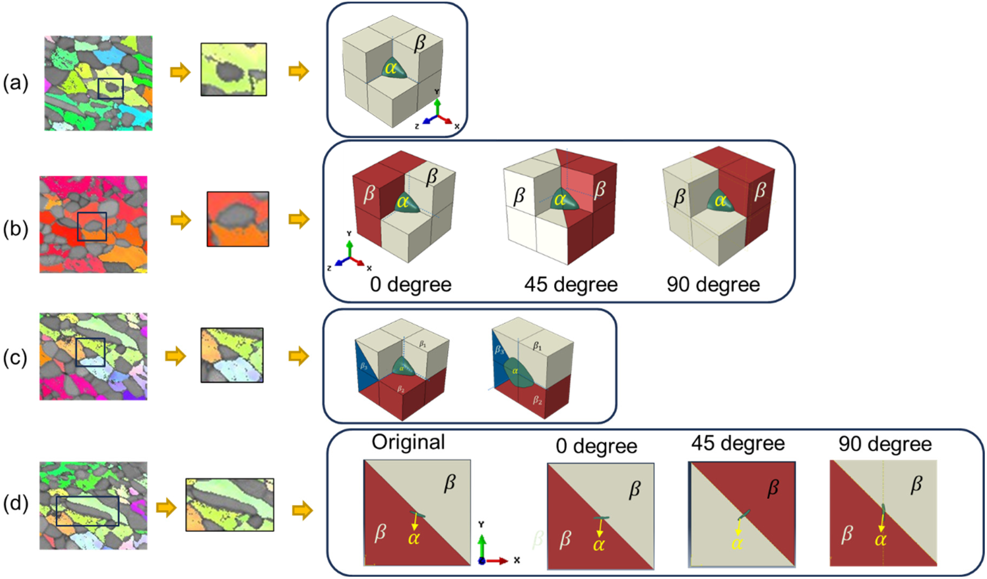
The representative volume element (RVE) configurations investigated in this study are directly informed by EBSD characterisation (Figure 6), which provides the grain morphology, phase distribution, and crystallographic orientations. The simulated cases, including embedded grains, grain boundary configurations, and triple junctions, represent experimentally motivated microstructural features commonly observed in Ti-5553 alloys. RVEs were constructed from EBSD maps to capture key microstructural features of the alloy (Figure 6). Three characteristic configurations were modelled:
an grain embedded within a grain (see Figure 6(a)),
an grain at the grain boundary of two grains (see Figure 6(b)),
an grain at the triple junction of three grains (see Figure 6(c)), and
an elongated grain aligned along the grain boundary between two grains (see Figure 6(d)).
Uniaxial experimental versus simulation stress–strain curves for dual-phase Ti-5553 alloy (21% phase and 79% phase) after parameter identification through inverse modelling approach.
RVE construction from EBSD maps showing three cases: (a) α grain inside , (b) α grain at boundary, (c) α grain at triple junction, and (d) elongated grain along boundary. RVE: representative volume element.
The RVEs used in this study are fully three-dimensional (3D). The initial microstructural information, including grain morphology and crystallographic orientations, was obtained from 2D EBSD maps. These maps were used to define the in-plane (XY) geometry of the microstructure. To construct a 3D RVE, the EBSD-derived microstructure, for example grain is first sketched in 2D using an EBSD map and then geometric operations (e.g. extrusion/revolve/sweeping within ABAQUS/CAE) are used around to create a 3D grain as shown in Figure 6. This approach preserves the experimentally measured grain size and orientation while enabling full 3D stress and strain evolution, including hydrostatic stress and triaxiality effects. The phase grains were embedded within the matrix by constructing 3D geometries using the EBSD-derived boundaries and subsequently generating volumetric grains via different geometric operations within the finite element preprocessing environment in ABAQUS/CAE. This ensured that the resulting RVE represents a volumetric microstructure rather than a 2D approximation.
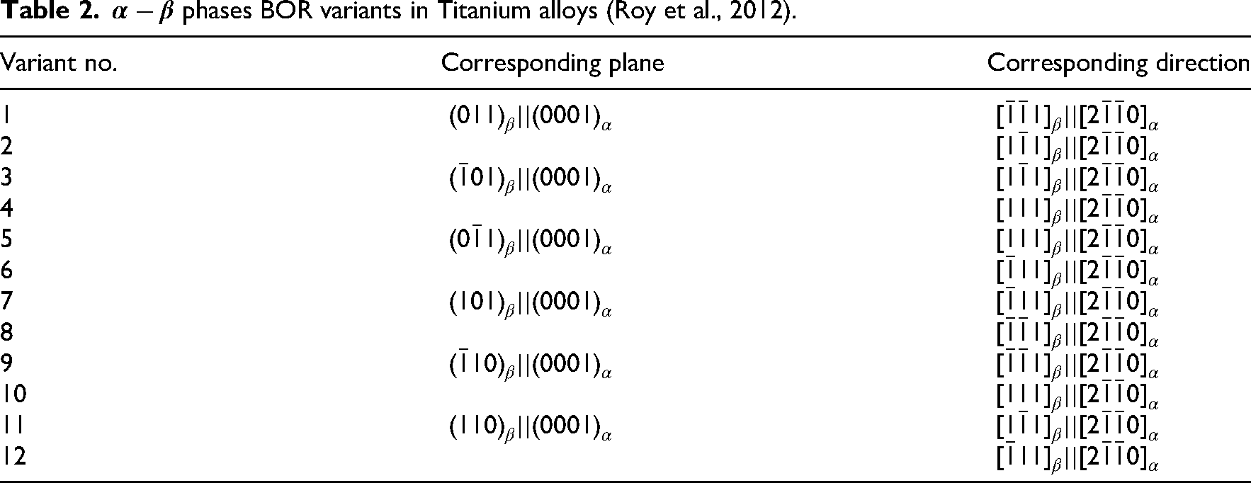
The BOR used in this study is based on established crystallographic relationships reported in the literature (Bin Asim et al., 2019, 2022; Roy et al., 2012). EBSD-derived grain orientations were used to define the α/β orientation relationship, ensuring consistency with BOR constraints. While TEM-based SAED validation is not included, the adopted BOR variants are representative of experimentally observed orientation relationships in titanium alloys. For the first configuration, where the grain is fully enclosed by a grain, the BOR was applied following (Bin Asim et al., 2019, 2022; Roy et al., 2012), which defines 12 possible transformation variants based on specific crystallographic plane and direction parallelisms (Table 2). However, Umair et al. (Bin Asim et al., 2019) demonstrated that the 12 BOR variants can be categorised into three families based on their mechanical response: BOR-A (Variants 1, 2, 5, 6), BOR-B (Variants 3, 4, 7, 8), and BOR-C (Variants 9, 10, 11, 12). Each family represents variants with similar slip and deformation behaviour, thereby reducing computational redundancy. In this study, the three BOR families (A, B, and C) were considered to capture the full range of variant responses. To explore the role of loading conditions, three different stress triaxialities () and three Lode parameters () were applied, covering a wide spectrum of stress states. The effect of crystal orientation was examined by rotating the grain from 0° to 90° relative to the major loading axis (X-axis in Figure 6) and changing the orientation while keeping the relative orientation in line with the specific variant type. Finally, the influence of phase volume fraction was investigated using 5%, 10%, and 20%.
For the second configuration ( Figure 6 (b)), where an grain was located at the grain boundary between two grains, the same loading parameters were applied, with the addition of grain boundary misorientation. Four different boundary angles (0°, 45°, and 90° with reference to loading plane, i.e. YZ plane) were simulated to capture the effect of interfacial geometry (Figure 6 middle RVEs).
For the third configuration ( Figure 6 (c)), grain was embedded at the triple junction of three beta grains. The fourth configuration focused on elongated grains located along grain boundaries. Four cases were considered: the experimentally observed orientation, and rotated orientations at 45°, 0°, and 90° ( Figure 6 (d)).
This systematic modelling framework enabled detailed exploration of the interplay between morphology, BOR variant families, applied stress state, grain boundary geometry, orientation, and phase fraction in controlling the local mechanical response of dual-phase Ti-5553 alloys.
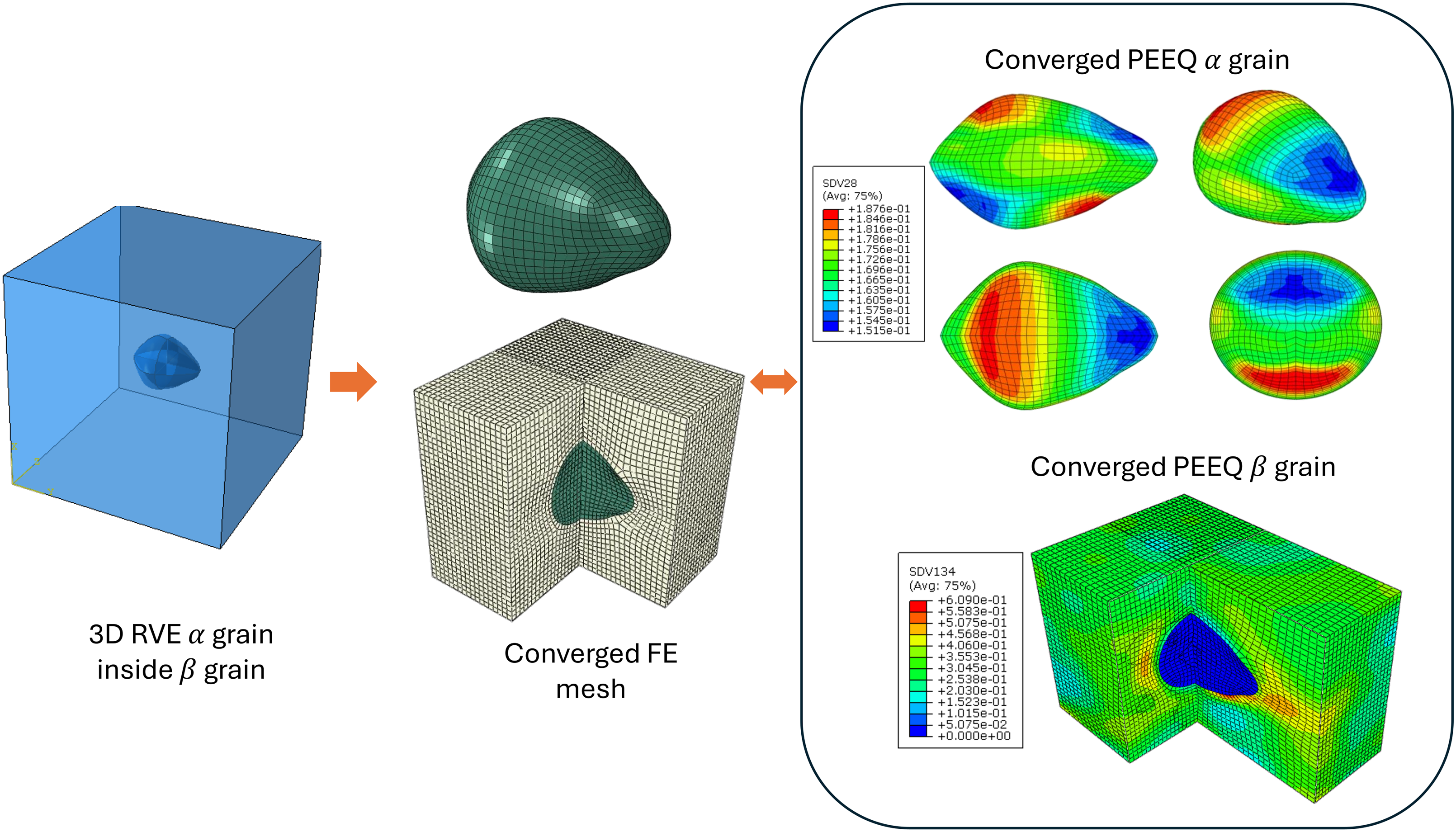
A representative example of the 3D RVE construction and meshing strategy is shown in Figure 7. The EBSD-informed microstructure is converted into a fully three-dimensional geometry by embedding grains within a grain and discretised using 3D solid elements. A targeted mesh convergence verification was performed on representative RVEs to ensure numerical accuracy. The mesh density was progressively refined, and convergence was evaluated based on key response variables, including equivalent plastic strain (PEEQ), maximum principal strain, and damage parameter (). It was found that mesh refinement did not result in any appreciable change in strain localisation patterns or damage distribution, with variations below 3% in peak PEEQ and damage parameter values. The final mesh used in this study therefore corresponds to a converged solution and provides an optimal compromise between computational cost and accuracy for 3D CPFEM simulations involving complex microstructures.
Construction and discretisation of the 3D representative volume element (RVE) derived from EBSD-informed microstructure. The α grain morphology is embedded within the β matrix and discretised using 3D solid elements. Representative contour fields are shown for the converged mesh, demonstrating the spatial distribution of deformation within the RVE. The selected mesh corresponds to a converged solution based on mesh verification.
Stress triaxiality () and the lode parameter () were maintained constant during loading using a multipoint constraint (MPC), defined as:
where and are the macroscopic hydrostatic and equivalent stresses of the RVE, and , , and are the first, second, and third macroscopic principal stresses, respectively. The MPC was implemented through an ABAQUS user subroutine. The methodology of Tekoğlu (2014) was employed to ensure constant stress triaxiality and Lode parameter during loading; details are omitted here for brevity (see Asim et al., 2019; Bin Asim et al., 2019; Ogosi et al., 2020 for more details). Simulations were performed at different stress triaxiality levels ranging from (uniaxial tension) to (crack-tip conditions). Various Lode parameters were considered: (axisymmetric tension), (pure shear), and (axisymmetric compression).
Results and discussions
It is important to note that the following results are interpreted as mechanistic predictions based on experimentally informed microstructures and calibrated constitutive behaviour. While the simulations capture local deformation and damage evolution at the grain scale, direct experimental validation of these local fields (e.g. slip activity and strain localisation) requires high-resolution techniques such as EBSD-based strain mapping or digital image correlation, which are beyond the scope of the present study. The following analysis focuses on relative trends in deformation, slip activity, and damage evolution across different microstructural configurations and loading conditions. Therefore, the interpretation of results is based on comparative behaviour rather than absolute stress–strain accuracy of individual-phases.
grain embedded within a grain: Effect of loading type
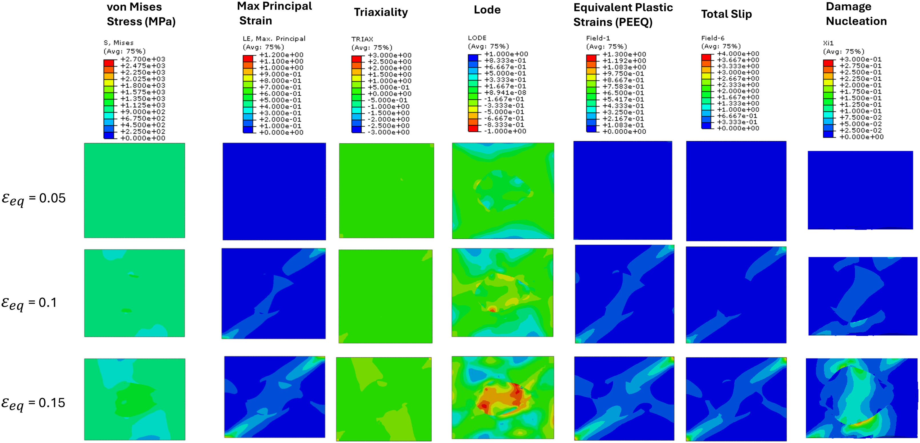
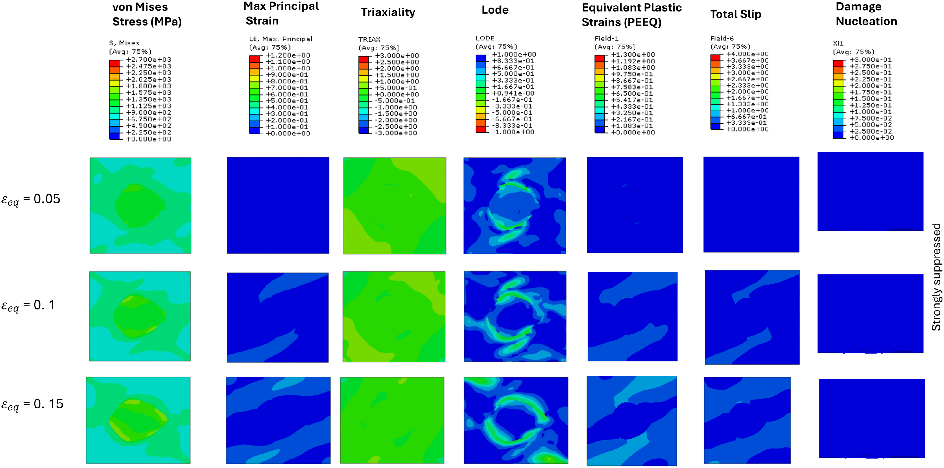
The simulation of a two grain microstructure (-HCP and -BCC; BOR-A, Variant 2) under moderate stress triaxiality ( and pure shear (Lode parameter ) has been examined at applied equivalent strains () of 0.05, 0.1, and 0.15(Figure 8) . The contour plots illustrate the evolution of von Mises stress, maximum principal strain, local stress triaxiality, local Lode values, equivalent plastic strain, and total slip fields, along with indicators of localised deformation and damage. At the lowest applied equivalent strain ( = 0.05), the microstructure uniformly develops moderate von Mises stress, with negligible strain localisation and no observable damage nucleation. At this low strain level, deformation remains predominantly elastic or in the early stages of plasticity, where grain size effects are not yet dominant. As a result, the stress distribution appears relatively uniform despite microstructural heterogeneity. With increasing strain, grain size and orientation effects become more significant, leading to localisation. As the applied strain increases to , clear localisation patterns emerge, reflected in concentrated maximum principal strains and plastic deformation (PEEQ). Regions of intensified total slip also start to form, indicating potential initiation sites for localised deformation and eventual damage at the grain boundary. It can also be inferred from Figure 8 for , grain develops a local tensile stress state with red zones of Lode going up to a value of −1. This also shows slip transfer starts to happen in grain along with a small amount of damage nucleation. At the highest strain level (), pronounced localisation becomes evident. The contour plots reveal sharp increase in maximum principal strain, substantial growth of plastic zone (PEEQ), and notable increase in von Mises stress, strongly correlating with intensified slip activity mostly in phase, but some amount transferring and happening in grain. Also, significant damage nucleation occurs at grain boundaries and interface regions, clearly highlighted by the damage nucleation contours. This is due to local stress triaxiality, and local Lode parameter as shown in Figure 8, which suggests a local axisymmetric tensile stress state in the grain and in the vicinity of the interface, causing a band of higher local stress triaxiality resulting in higher damage nucleation and evolution in those regions. These observations imply that under moderate triaxiality and shear-dominated loading (; ), the microstructure exhibits moderate ductility with damage initiation governed primarily by shear-induced localisation at grain boundaries and interfaces. Early slip localisation acts as a precursor to void nucleation, and damage tends to occur at moderate applied strain levels. The phase, being softer, accommodates more slip and contributes to overall ductility, but slip transfer into the grain concentrates deformation at the interface. These results are consistent with (Qin and Li, 2019), where it was reported that shear dominated deformation promotes slip banding before void nucleation and growth for different strain rate cases.
In the second case, the simulation of the same two-grain RVE (BOR-A, Variant 2) under moderate stress triaxiality () and axisymmetric compression stress state () has been analysed at applied equivalent strains () of 0.05, 0.1, and 0.15 (Figure 9). At the lowest strain level (), von Mises stress is moderately elevated across both grains, with the grain showing slightly higher stress concentration. However, there is negligible strain localisation at this stage, and both maximum principal strain and equivalent plastic strains (PEEQ) contours remains negligible. Slip activity and damage nucleation are minimal, indicating a predominantly elastic or early plastic response. As the applied equivalent strain increases to , more distinct localisation becomes visible. The surroundings of grain begins to develop banded regions of elevated principal strain and equivalent plastic strain. The von Mises stress also increases notably within the grain, indicating that the load path is driving compression induced local stress concentration in the phase. The Lode parameter reveals early elliptical patterns encircling the grain, driven by interfacial stress mismatch. While still limited, early signs of slip concentration and phasewise mechanical incompatibility are evident around grain. At the highest strain level analysed (), the localisation becomes more defined. Principal strain and equivalent plastic strain fields reach their maxima within the grain and at the interface, however the values are much lower than previous loading case of ; . The ring-like slip band becomes more pronounced and thicker, suggesting an evolution of shear-localised deformation bands due to axisymmetric compression. There is very small (negligible as compared to previous case) amount of slip transfer or slip found in grain for all three applied strain values. Most importantly, despite the local strains, damage nucleation remains negligible, suggesting enhanced stability of the interface under axisymmetric compression loading. These observations imply that under moderate triaxiality and Lode parameter , the microstructure undergoes a deformation mode dominated by compression and supportive plasticity in the phase. Compared to pure shear case () loading, the tendency for interface driven voiding is reduced, and instead, plastic strain accumulates in the grain without rapid decohesion. Slip localisation still serves as a precursor to possible failure, but the system remains stable. This aligns with experimental observations (Qin and Li, 2019) that under compressive stress state void nucleation is reduced.
For the third case, the simulation of a two-grain RVE (BOR-A, Variant 2) under same moderate stress triaxiality (), while axisymmetric tension stress state () has been investigated at applied equivalent strains () of 0.05, 0.1, and 0.15 (Figure 10). At the lowest strain level (), both grains exhibit uniform von Mises stress and maximum principal strain distribution, with slightly higher von Mises stress in the grain. The PEEQ, total slip and maximum principal strain fields are low in magnitude, with no significant strain localisation or slip concentration visible. However, local stress triaxiality and Lode parameter show band of higher triaxiality and Lode values around grains, showing potential areas of plastic deformation and damage. As the strain increases to , tension in major loading direction (horizontal) becomes more apparent. Maximum principal strain and plastic strain fields begin to intensify around the grain, especially in the interfacial regions. A characteristic ring of slightly higher Lode parameter is more visible around the grain, especially at the top and bottom interface between indicating different local axisymmetric tensile conditions, which causes variable void nucleation around the grain. This is visible in damage nucleation and more severe around the grain boundary normal to the horizontal loading direction. At the highest applied strain (), this trend becomes more severe. The maximum principal strain and PEEQ fields show intensification between interface. Most notably, the damage nucleation field shows clear activation at the grain boundary and within the grain, especially in regions aligned with the major tension loading direction (horizontal direction). This damage pattern indicates that void formation is primarily controlled by the tensile stress state, exacerbated by the limited slip capacity of the phase and stress transfer from the more ductile β matrix. These results demonstrate that under moderate triaxiality and loading, the microstructure exhibits an early onset of damage. Compared to the and cases, the cause axisymmetric tension state that significantly enhances the risk of intergranular failure and internal void nucleation within the phase. This behaviour shows that axisymmetric tension promotes triaxial stress concentration and volumetric strain, which are conducive to void growth and decohesion. Axisymmetric tension (L = −1) promotes early void nucleation due to the elevated hydrostatic stress component, which enhances volumetric strain and accelerates void growth. According to classical ductile damage models (see Bin Asim et al., 2019 and references therein), void growth rate increases exponentially with stress triaxiality, making tensile stress states particularly prone to damage initiation and evolution. Thus, this loading scenario represents a damage-prone condition, where moderate ductility is rapidly overcome by tensile-driven localisation and interfacial decohesion.
Contour plots of von Mises stress, maximum principal strain, local stress triaxiality, local lode parameter, total slip, and damage nucleation/growth fields in a two-grain (-HCP and -BCC) RVE, for BOR-A (Variant 2), under and at , , and , showing progressive localisation and damage initiation at grain boundaries and phase interfaces. RVE: representative volume element.
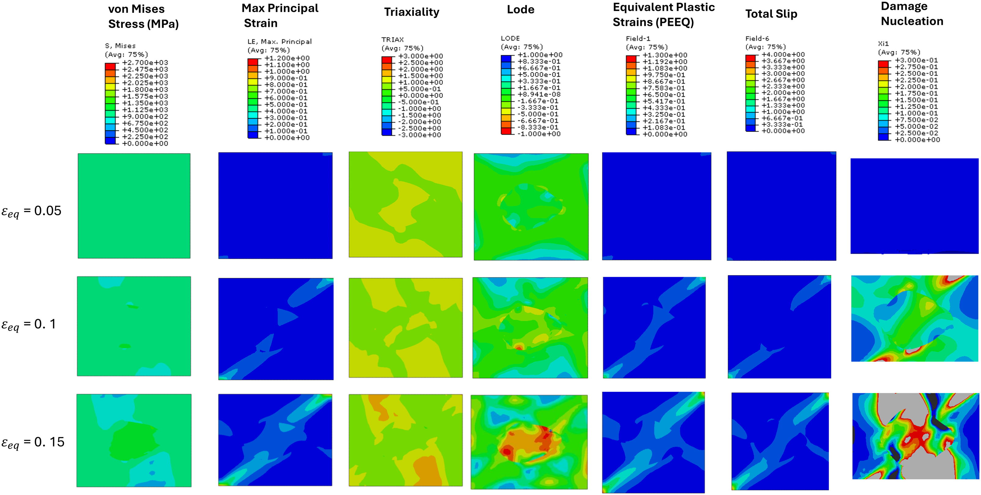
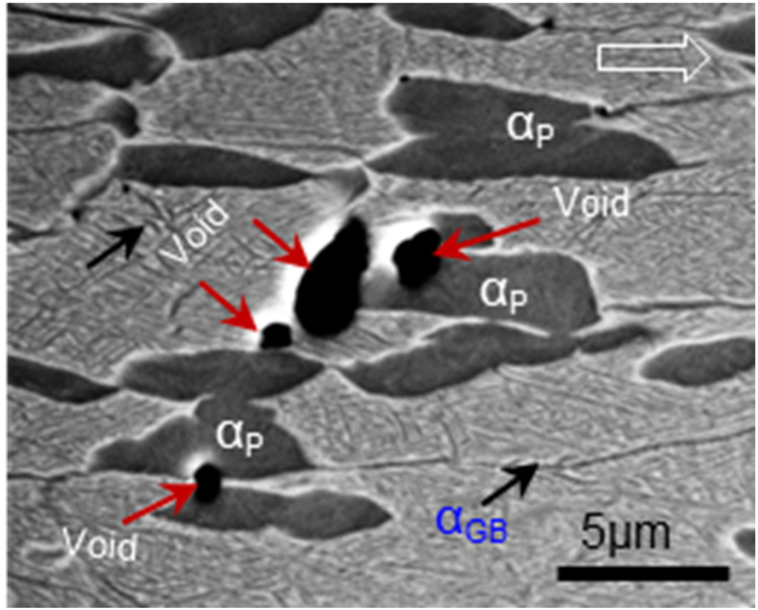
The simulation of a two-grain microstructure (-HCP and -BCC) under high stress triaxiality () and pure shear stress state (Lode parameter, ) has been examined at incremental applied equivalent strains () of 0.05, 0.1, and 0.15 (Figure 11). The contour plots illustrate the evolution of von Mises stress and strain fields, along with indicators of localised deformation and damage initiation. At the lowest strain level (), von Mises stress is uniform across the microstructure. The maximum principal strain and PEEQ fields also remain fairly uniform and are very small. Slip activity is very limited, and damage nucleation is absent, indicating predominantly elastic or early–stage plastic deformation. As strain increases to , the mechanical response begins to shift. Pronounced principal strain, PEEQ, and slip localisation emerges within the β grain and at the grain boundary region. The plastic strain (PEEQ) field shows intensified concentration in the phase, confirming the higher slip accommodation capability of the BCC structure under elevated triaxial stress, while grain shows shear deformation causing plastic slip transferring into it. At this stage, small but significant regions of damage nucleation begin to appear, particularly at interfaces. At the highest strain level (), localisation becomes severe. The principal strain and PEEQ plots exhibit intense gradients, with well-defined plastic zones concentrated in the grain and along intergranular regions. The total slip contour reflects a network of shear bands spanning the RVE, while the von Mises stress continues to concentrate at internal heterogeneities, i.e. grain. The damage nucleation field reveals large-scale void formation near the interface, with grey zones indicating possible failure beyond damage threshold of 0.3. This is attributed to the combined influence of high triaxiality and shear, which elevates the hydrostatic stress and promotes void nucleation and growth. These results suggest that under high triaxiality and pure shear (, ), the microstructure undergoes a highly unstable deformation path, characterised by strong localisation in the phase and rapid damage evolution at interfacial regions. Compared to moderate triaxiality cases (), damage initiates earlier and progresses more rapidly, particularly where shear bands intersect with stress concentration zones. The phase, while initially accommodating plasticity, becomes a site of critical stress build-up, triggering failure mechanisms when triaxial tension interacts with intense local shear. Thus, this condition represents a high-risk regime for ductile failure, where elevated hydrostatic stress accelerates damage onset in a microstructure already predisposed to interface-driven localisation. We also found similar damage profile in the Ti-5553 near the fracture tip of the tensile tested sample (see Figure 10), which is shown in SEM micrograph presented in Figure 12. It is clear from micrograph that voids are generated close to the particle and also in between them. Interaction of slip/deformation bands activated in matrix around them during the deformation is believed to be prime reason for the initiation of damage shown in Figure 11.
Contour plots showing the evolution of von Mises stress, maximum principal strain, stress triaxiality, lode, equivalent plastic strain, total slip, and damage indicators in a two-grain RVE (BOR-A, Variant 2) subjected to moderate triaxiality () and axisymmetric compression (lode parameter ) at , , and .
Contour plots showing the evolution of von Mises stress, maximum principal strain, stress triaxiality, lode, equivalent plastic strain, total slip, and damage indicators in a two-grain RVE (BOR-A, variant 2) subjected to moderate triaxiality () and axisymmetric tension (lode parameter ) at , , and .
Contour plots showing the evolution of von Mises stress, maximum principal strain, stress triaxiality, lode, equivalent plastic strain, total slip, and damage indicators in a two-grain RVE (BOR-A) subjected to high triaxiality () and pure shear (lode parameter ) at , , and , demonstrating pronounced localisation and accelerated damage evolution at interfaces compared to lower triaxiality () loading conditions.
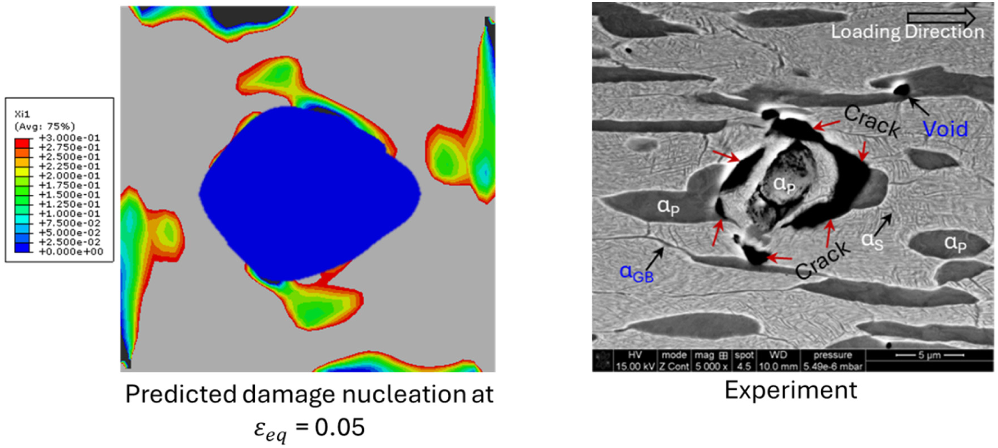
In addition to the above loading conditions, simulations were performed for , representing very high triaxiality, combined with Lode parameters and . At , , the deformation remained stable up to . Similar to other triaxialities at , no significant damage nucleation is observed. At , , severe void nucleation and growth is observed much earlier than the lower triaxialities, with failure localising in the diagonal shear zones and surrounding the grain entirely, as was the case for lower triaxialities, while showing similar failure profiles as shown in Figure 13. The SEM micrographs (Figures 12 and 13) show void nucleation and coalescence near interfaces, which is consistent with the damage mechanisms predicted by the CPFEM simulations. While SEM does not provide crystallographic or strain-resolved information, the observed fracture features qualitatively support the predicted localisation of damage at phase boundaries under tensile loading.
SEM micrograph from regions close to fracture surface/tip of tensile tested samples of Ti-5553 showing the damage occurred around grain.
Predicted damage (, ) at (left) and SEM micrograph from a region near the fracture surface/tip of Ti-5553 alloy sample (right) showing due to coalescence of voids generated around grain () under tensile loading.
It is important to note that while the present study integrates EBSD-informed microstructures and experimental stress–strain calibration, full-field experimental validation of strain localisation remains beyond the scope of this project due to experimental limitations. The SEM fractography presented (Figures 12 and 13) provides qualitative validation of void nucleation and coalescence mechanisms predicted by the CPFEM framework. Future work will focus on integrating DIC and high-resolution EBSD-based strain mapping to enable direct quantitative validation of localisation and damage evolution. This will be reported in the near future.
Slip activity and void damage as a function of orientation
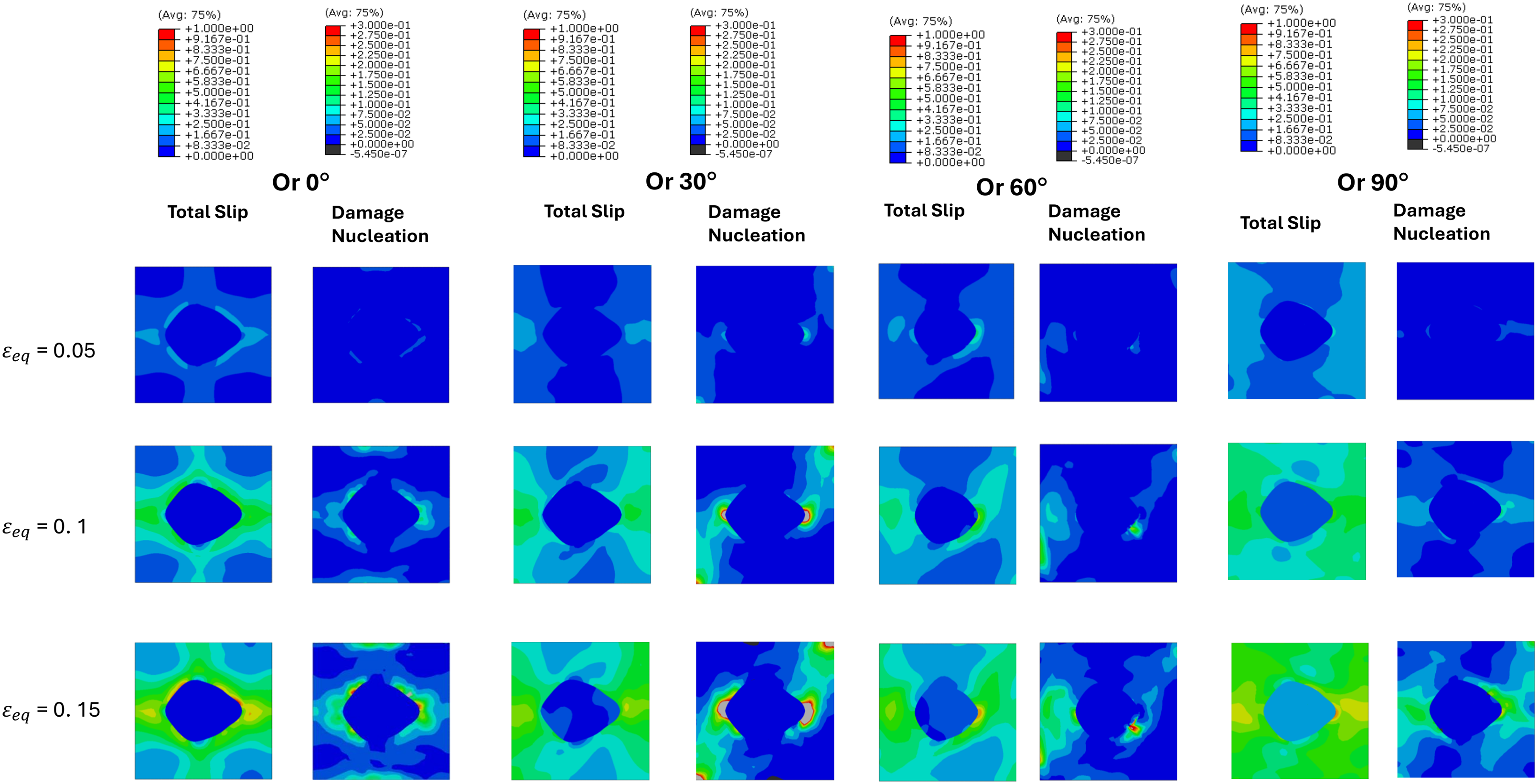
This section presents crystal orientation effects with reference to major loading direction. RVE is constructed for BOR-C (Variant 10), the orientation relationship was kept fixed to this variant. However, we rotated the crystal pair relative to the loading axis. The evolution of slip and damage in the four orientation pairs (0°, 30°, 60°, 90°) is shown in Figure 14 under moderate stress triaxiality (), while axisymmetric tension stress state (). Each column pair presents slip activity (left) and damage nucleation (right) for increasing applied equivalent strain. For 0° orientation, slip in the grain is effectively suppressed this is due to c-axis alignment with the loading axis for this orientation, and deformation localises within the matrix. Damage initiates early at the interface and extends over ∼30–35% of the matrix at maximum strain, indicating interface fracture dominated failure with moderate ductility. At 30° orientation, limited slip develops in due to limited slip continuity across the interface. At 0.1 and 0.15 peak strain, interfacial damage reaches critical value (grey zones) covering some areas of the matrix around the interface, reflecting a moderate-to-brittle response. The 60° orientation exhibits the favourable behaviour. Activation of slip in , compatible with slip, promotes more homogeneous strain transfer as compared to 0° and 30°. Damage remains below critical value across all strain levels, with no grey zones observed. Only small, localised lobes occur near regions of high curvature. This orientation displays the slowest damage accumulation and high ductility, but with localised damage risks. At 90°, slip is broadly distributed in both phases, but at curved interface corners orthogonal to loading direction drive damage in the β matrix. This orientation shows a moderate ductile response. It must be noted that in this study, the crystallographic relationship was defined using BOR-C (Variant 10). This variant aligns the basal plane () of with a () plane of and establishes a near-parallelism between and type slip directions. Such alignment promotes favourable slip transmission across the interface, particularly for basal/prismatic systems in that share compatibility with active (110)[111] systems in . This crystallographic compatibility underpins the observed behaviour in the 60° orientation case, where distributed slip in is effectively transferred into , delaying damage localisation. Conversely, when the grain is rotated to 0° or 30°, slip systems lose direct correspondence with those in , suppressing plasticity and leading to stress intensification and early interface damage. At 90°, slip is broadly activated in both phases, but damage persists at high-curvature interface regions, consistent with partial but incomplete slip system matching under BOR-C (Variant 10). It is found that orientations that raise shear on geometrically compatible - and -directions promote smoother strain sharing and delayed interface damage, while less favourable orientations supress activity and concentrate damage at the boundary. This orientation sensitive behaviour is consistent with reports that grain orientation governs strain partitioning in Ti-5553 (Agius et al., 2021) and with interfacial crack path studies in near alloys (Qin and Li, 2019; Qin et al., 2024; Sen et al., 2019).
Effect of volume fraction on slip and damage evolution
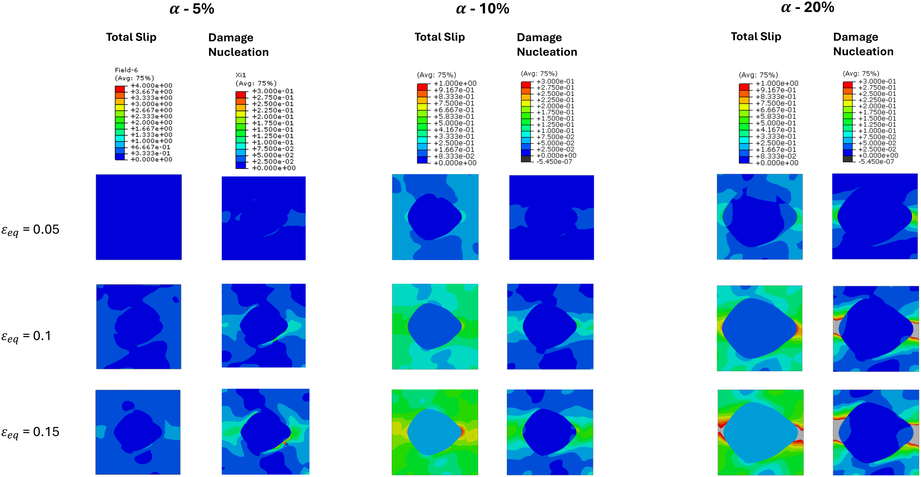
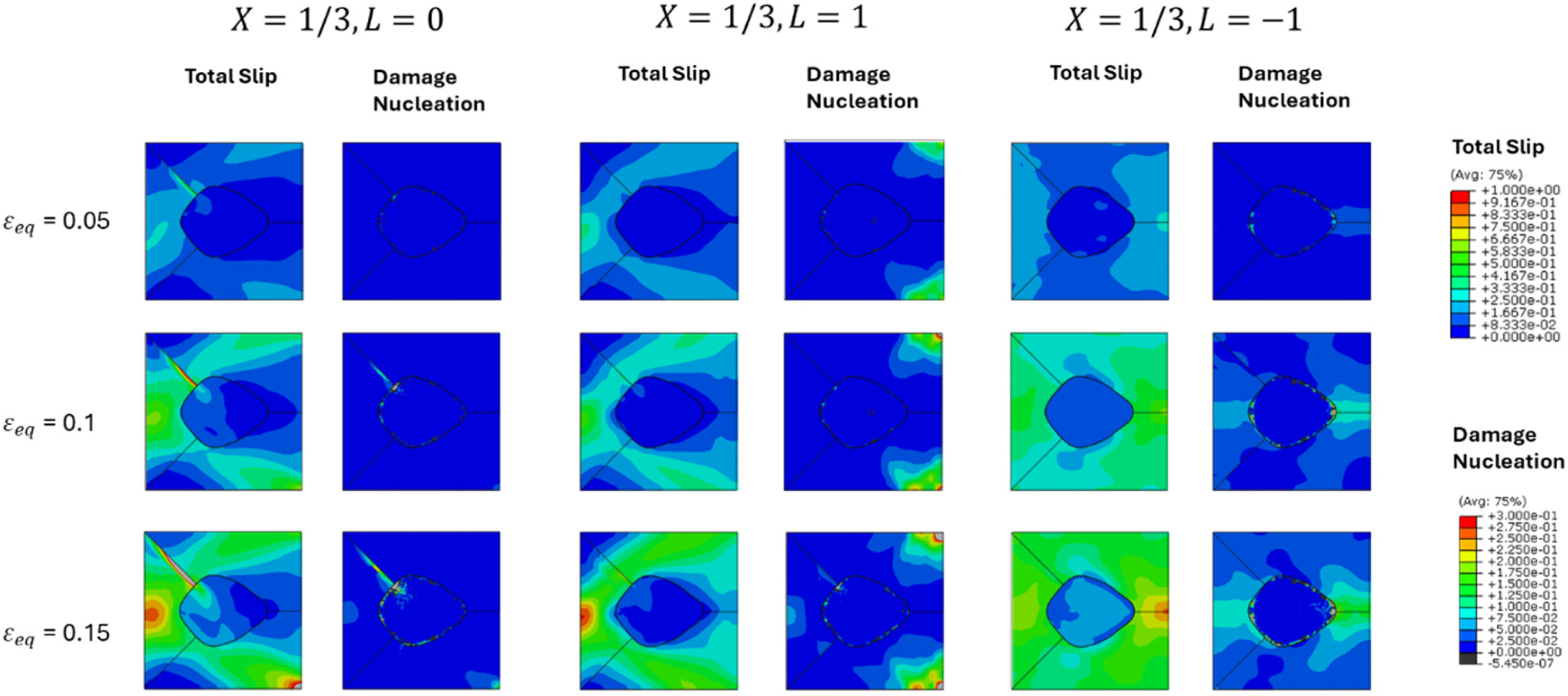
Figure 15 compares slip and damage nucleation for three volume fractions under the combined loading state of triaxiality and Lode parameter . Rows correspond to increasing applied strain, and columns to slip and damage nucleation fields for each volume fraction, viz. 5%, 10%, and 20% of phase.
At low volume fraction (-5% RVE), slip is dominated by the matrix, with almost negligible activation in the lower volume fraction grain. behaves like hard particle in a softer matrix, resulting in highly localised slip bands within initiating at the grain boundary and expanding in the phase away from the interface. At a strain level of 0.1, damage initiates along grain boundaries, and by maximum strain (0.15), damage zones coalesce in the β dominated regions. Although early voiding is evident, overall matrix continuity delays catastrophic failure, giving a moderate ductility response which is controlled entirely by phase. At 10% volume fraction, slip activity is distributed more evenly across both phases. The grain shows slip activity which depicts transfer of deformation compatibly into neighbouring and vice versa. This synergy suppresses extreme localisation as compared to previous (5% phase case) and interfacial voiding is more distributed in the loading (horizontal) direction. By the highest strain of 0.15, damage nucleation remains moderate (<0.2), with only small damage regions forming at high curvature interfaces which are orthogonal to loading direction. Ten percent volume fraction case therefore provides the most damage tolerant response, as the two phases complement each other mechanically. At high volume fraction (20% RVE), deformation is strongly influenced by plasticity. Although slip in is widespread, stress is not effectively relaxed by the reduced fraction. Consequently, void damage accumulates rapidly at interfaces orthogonal to loading direction, especially near curved boundaries, reaching values >0.3 by the final strain of 0.15. This dominated microstructure exhibits brittle-like behaviour because the limited phase reduces plastic energy dissipation and imposes additional constraints.
These results demonstrate a non-monotonic dependence of damage nucleation and growth on volume fraction. While both 5% and 20% phase cases exhibit localised damage and accelerated failure modes, the 10% configuration achieves the most favourable combination of distributed slip and suppressed void nucleation. This underscores the importance of phase volume fractions in dual-phase alloy, viz. not only the presence of hard or soft phases, but their volume fraction and connectivity critically govern resistance to void-driven damage under mechanical loading. Similar strength vs ductility trade-offs with volume fraction and morphology are reported in near alloys (Sen et al., 2019; Shekhar et al., 2015), with bimodal microstructures often exhibiting improved balance (Qin and Li, 2019).
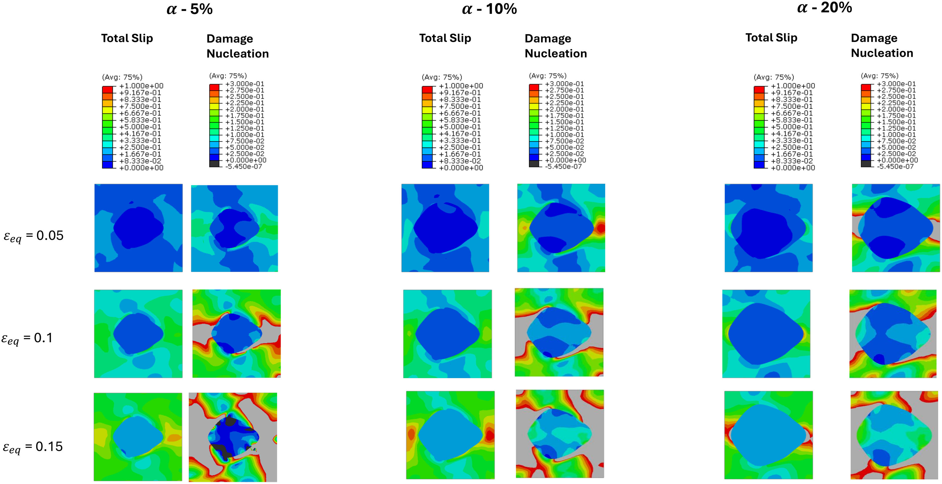
Figure 16 shows slip and damage nucleation fields for three volume fractions under a stress triaxiality of and Lode parameter of . Compared with the lower stress triaxiality case of , the higher hydrostatic stress strongly accelerates void nucleation and growth across all microstructures. Also, the phase volume fraction dictates both the location of strain localisation and the severity of damage accumulation. In the first case with 5% phase RVE, deformation is dominated by the matrix. Slip activity is widespread in , while the grain acts primarily as a hard inclusion with limited activation. Damage initiates along interfaces and within grain, but phase allows for the redistribution of stress and slip. As a result, grey regions (damage >0.3) emerge (see and higher in Figure 16 for 5% case), and failure develops in a matrix-controlled ductile mode. In the 10% case, slip is more evenly partitioned between the two phases. Both slip and damage are much higher as compared to 5% volume fraction case. This high triaxiality case shows much earlier damage as the volume fraction of is increased. Similar is observed in 20% volume fraction case (as shown in Figure 16), where a higher amount of slip is transferred in the grain and damage is much widespread due to less amount of phase material.
Contour plots of accumulated slip (left column of each orientation pair) and damage nucleation (right column) for orientation rotations of 0°, 30°, 60°, and 90° (BOR-C; Variant 10; ) under increasing applied equivalent strain (rows 1–3). Grey regions correspond to damage values exceeding 0.3, indicating imminent failure.
These results show that with increasing stress triaxiality there is a monotonic dependence of damage nucleation and growth on volume fraction, i.e. for and higher. Lower volume fraction of (5%) showed the most damage-resistant response through effective slip transfer and phase constraint. Importantly, the differences between the three cases are amplified at high triaxiality, emphasising the need to optimise phase balance when designing dual-phase alloys for service under hydrostatic stress conditions.
Finally, a direct comparison between the and cases with highlights the amplifying role of hydrostatic stress on damage nucleation and growth across all volume fractions. At , the balanced configuration (10% volume fraction) delayed damage initiation and confined voiding to small interfacial zones, while both 5% and 20% cases exhibited earlier localisation through matrix- and interface-driven mechanisms, respectively. At T = 1 and higher triaxialities, an increase in volume fraction of phase showed earlier failure as volume fraction of was increased from 5% to 20%. Also, the differences were magnified: grey damage regions emerge earlier, damage spreads more extensively, and all the three volume fractions of (5%, 10%, 20%) showed reduced tolerance. The rich RVE becomes particularly unstable under high triaxiality, with rapid interfacial coalescence dominating failure. These observations confirm that phase volume fractions govern the mode of deformation, and damage nucleation/growth, applied stress state also controls the damage rate.
Slip distribution and damage in RVEs with grain located at the grain boundary between
two grains
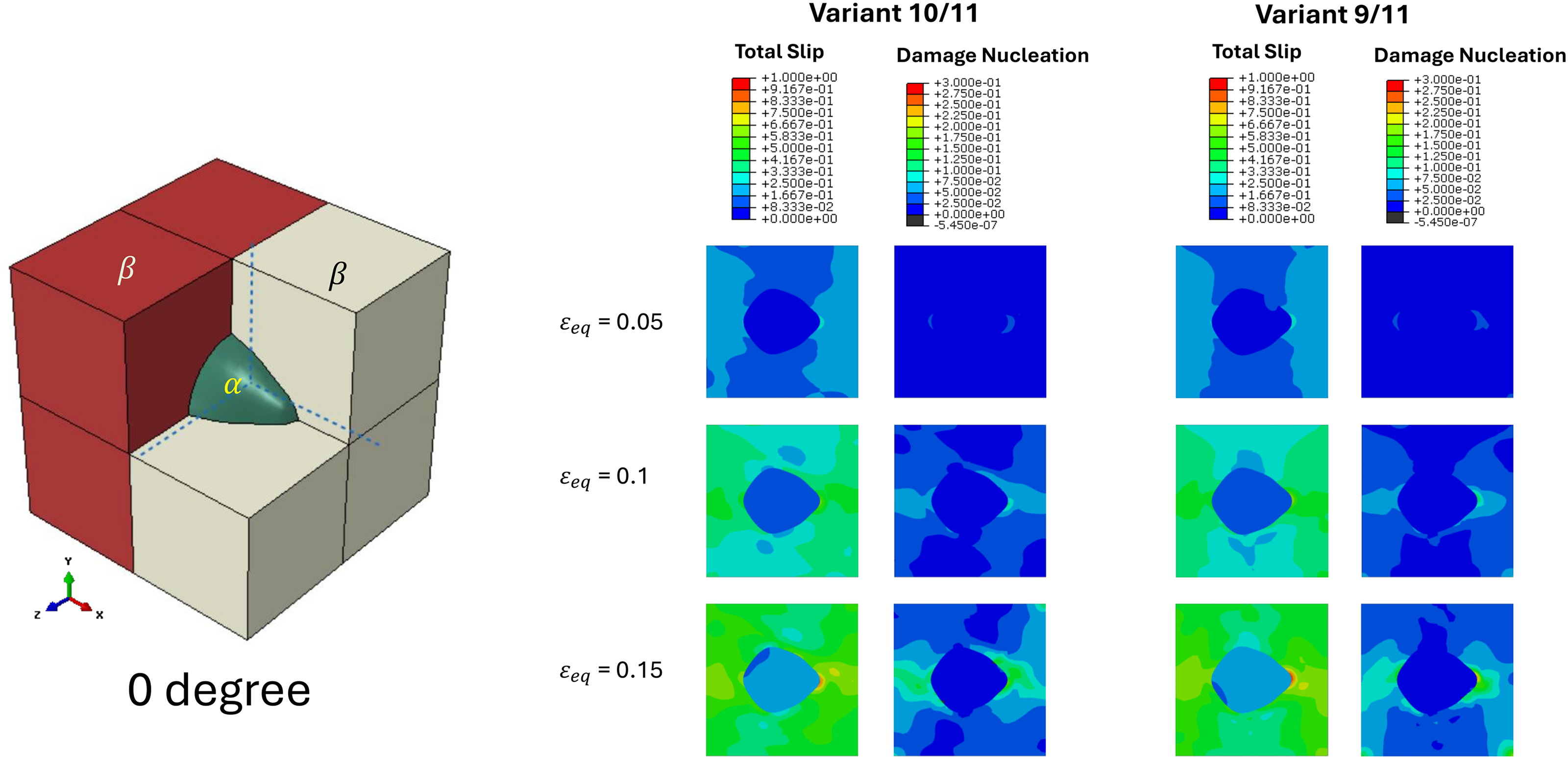
For the second scenario from EBSD maps and RVEs discussed in the representative volume element models section, RVE simulations were performed with an grain located at the interface between two grains (Figure 6(b)) . Two variant combinations were analysed, viz. 10/11 and 9/11 (see Table 2). The microstructures were subjected to uniaxial tensile loading with , and . The evolution of total slip, damage nucleation and growth is presented in the following at equivalent strains of 0.05, 0.10, and 0.15.
Figure 17 shows the slip and damage fields for both cases. The 10/11 BOR variant combination, exhibited slight asymmetry and homogeneous slip distributions. At , slip was broadly uniform, with little localisation near the boundaries. Even at , slip remained relatively well distributed with phase in variant 11 showed higher concentrated slip at the interface as compared to variant 10. Low damage nucleated at the grain boundaries orthogonal to the loading direction (horizontal). By contrast, the 9/11 BOR variant combination introduced a significant crystallographic misorientation between the two grains. At , similar to 10/11 variant, a slight asymmetry in the slip field was evident. With increasing strain, strong slip localisation developed along both interfaces. At , these localised regions correlated with pronounced damage nucleation and growth on variant 11 side, concentrated at interphase boundaries with higher concentrated slip and damage at the interface as compared to variant 9.
Effect of volume fraction on slip and damage nucleation under triaxiality and lode parameter (BOR-A, Variant 2). Each column pair corresponds to a different phase fraction: 5% (left), 10% (centre), and 20% (right). Within each pair, the left panel shows accumulated slip and the right panel shows damage nucleation. Rows represent increasing applied equivalent strain.
Based on the above, it can be inferred that lower misorientation between grains, as in the 10/11 variant case, promotes more homogeneous plasticity with lower and well-distributed damage nucleation and growth. Conversely, the higher anisotropy of the 9/11 variant pair intensifies damage localisation and accelerates damage nucleation/growth.
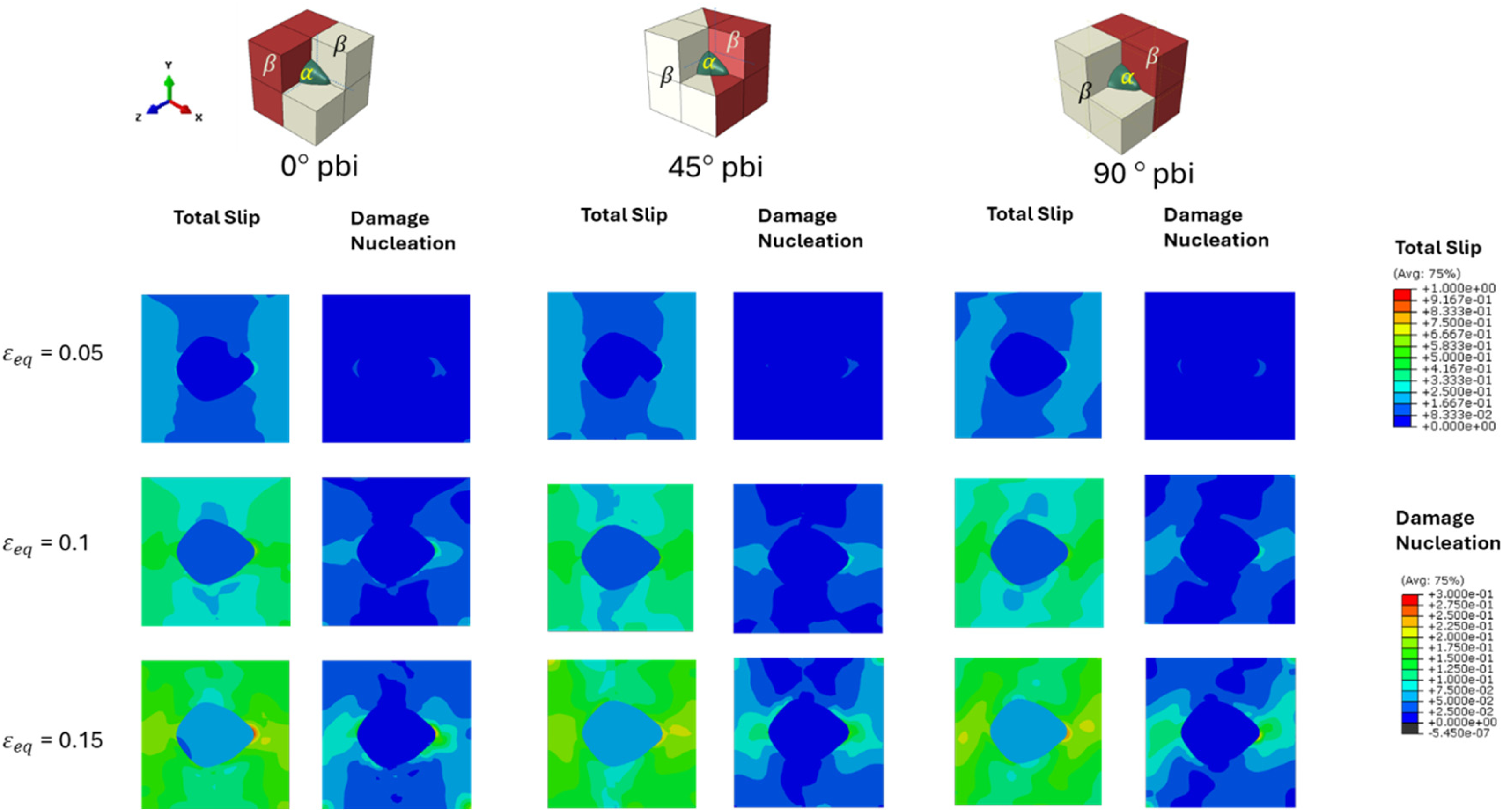
In order to understand the effect of phase boundary inclination (pbi) between two grains and one a grain, RVEs were constructed for 0°, 45°, and 90° phase boundary inclinations with respect to YZ loading plane (see Figure 18). For all the simulations variant 9/11 was selected based on the above discussion, where this variant was found to be more damage-prone. 0° pbi has been presented above and not repeated here for brevity. For the case of 45° pbi, slip shows a similar profile as 0° pbi. Damage remains localised but lower than 0° pbi at high-curvature grain boundaries orthogonal to the horizontal loading direction. This configuration of RVE delivers the most damage-tolerant response for 9/11 variant, because interface shear between two grains is converted into through and around transfer instead of piling up along the boundary.
Effect of volume fraction on slip and damage nucleation under triaxiality and lode parameter (BOR-A, Variant 2). Each column pair corresponds to a different phase fraction: 5% (left), 10% (centre), and 20% (right). Within each pair, the left panel shows accumulated slip and the right panel shows damage nucleation. Rows represent increasing applied equivalent strain.
Rotating the pbi to 90° aligns it to the loading direction, so primary slip impinges directly on the boundary on both sides of . This reduces intergranular compatibility and promotes shear accumulation at the two junctions. The result is a pair of symmetric damage pockets that nucleate at the high curvature boundary adjacent to the boundary and then extend along the boundary plane. Compared with 45°, localisation is stronger; compared with 0°, the damage is more spread, favouring damage zone linkage along the interface. The RVE thus shows a transition from distributed side damage to boundary-assisted damage nucleation and growth.
These results demonstrate that the inclination of the phase boundary controls how slip transfers through and around the interfacial . Therefore, governs where and how damage localises. The 45° case shows the most damage-tolerant behaviour due to effective slip redistribution, while the 0° case promotes boundary parallel pile-up, and the 90° case leads to more pronounced boundary-guided nucleation and growth. These findings suggest that phase boundary orientation can play a decisive role in delaying or accelerating microcrack initiation in dual-phase Ti-5553 alloys.
Effect of grain located at the triple junction on slip distribution and damage
Figure 19 shows the evolution of total slip and damage nucleation in the RVE containing an grain positioned at the triple junction of three grains (β₁, β₂, β₃). The orientation relationships follow BOR-4, BOR-5 and BOR-11 for , and interfaces, respectively. Simulations were carried out at a moderate stress triaxiality () for . Equivalent strain () levels of 0.05, 0.10, and 0.15 were examined. At , (pure shear), the deformation remains largely uniform at low strain. Slip initiates in the grains and gradually extends along the boundary. The grain stays mostly elastic at . By , slip bands intersect near the interface, forming small damage nuclei at the triple junction. At , damage remains modest and localised along the perimeter and boundary. At , (axisymmetric compression), the microstructure shows stable deformation. Slip is primarily accommodated by the surrounding matrix, while the grain shows a very small amount of plastic slip. Damage nucleation is negligible up to the maximum strain of 0.15, confirming that compression suppresses interfacial decohesion and confines strain localisation within the grains.
RVE simulations of an grain at a interface for variant pairs 10/11 and 9/11 under uniaxial tension (, ). Total slip (left) and damage nucleation (right) are shown at equivalent strains of 0.05, 0.10, and 0.15. RVE: representative volume element.
Under , (axisymmetric tension), the response becomes more localised. At , slip begins within grains with limited activity inside . By , stress transfer through the interfaces leads to concentrated slip around the triple junctions, accompanied by early void nucleation along and boundaries. At , damage zones expand and intensified, indicating that tensile loading elevates hydrostatic stress and accelerates interface failure at the triple junction and nearby boundaries between and which are orthogonal to the horizontal loading direction.
The triple-junction configuration creates a competitive constraint among the and interfaces. Under shear or compressive loadings (L ≥ 0), deformation remains distributed and interfacial damage is limited. Under tensile loading (L = –1), hydrostatic stress localises at the triple junctions, causing early void nucleation and accelerated damage growth. Hence, triple junctions act as potential initiation sites for failure in tension but remain stable under shear and compression.
Effect of elongated grain orientation at the interface
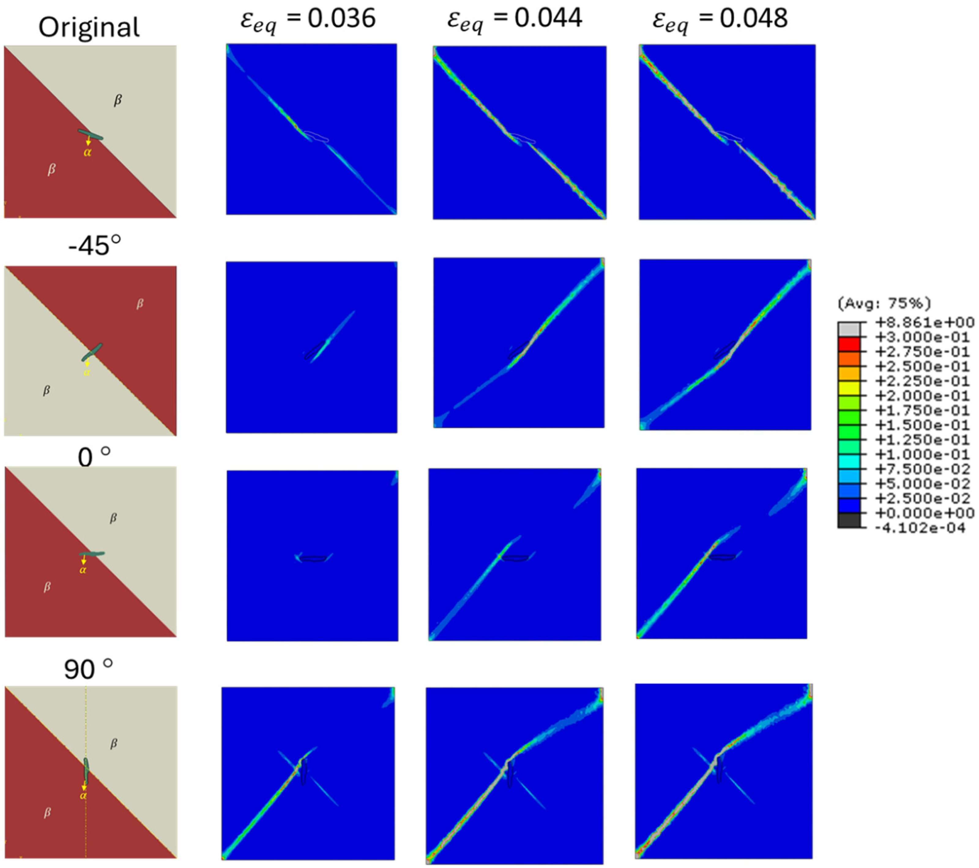
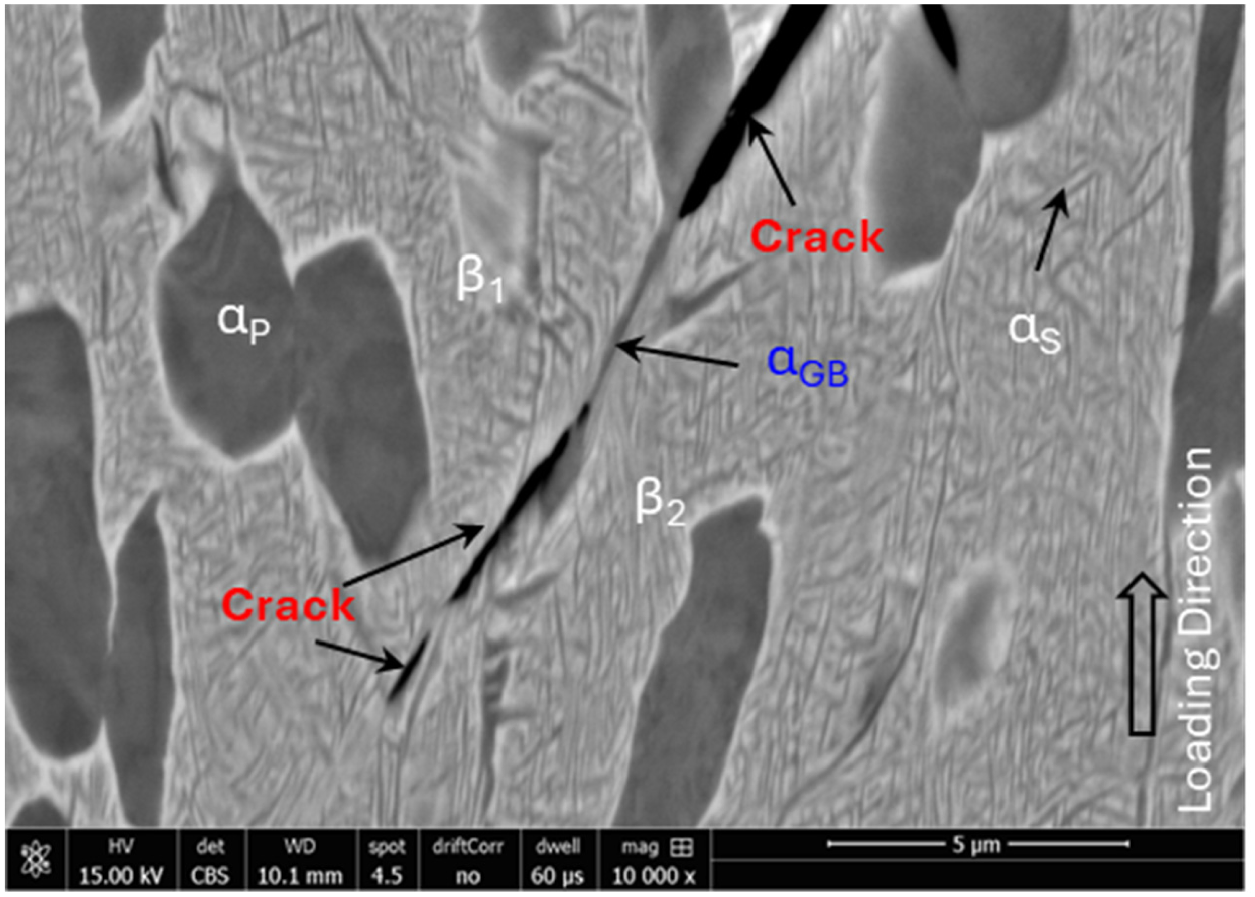
The role of elongated grain which sometimes also classed as grain boudary () at grain boundary (see Figure 6(d)) was investigated under a loading state of and . The original baseline orientation similar to the one in the EBSD map shown in Figure 6(c) and three additional cases representing plausible rotations of the grain (–45°, 0°, and 90°) as could arise during forging are used to construct RVEs. The results (Figure 20) show that the orientation of the elongated grain strongly influences damage nucleation patterns. In the original baseline case, where the elongated grain is aligned close to the diagonal grain boundary in the matrix, damage bands from adjacent grains initiate at the grain boundary at shallow incidence angles. These damage nucleation bands then extend as the applied strain increases along the grain boundary. This behaviour indicates that in this alignment, the elongated acts as a bridge for damage transfer rather than a strong barrier. Similar behaviour was found while performing SEM analysis of the microstructure near the fracture surface as shown in Figure 21, where it was found that crack nucleated along the elongated grain ( grain boundary) travelling along the two grains boundaries.
Slip and damage evolution for variant 9/11 with an grain at the interface, shown for different phase boundary angles under uniaxial tension (, ).
Total slip (left) and damage nucleation (right) contours for an RVE with an α grain at the triple junction of three β grains (β1–β3) under different stress states. Simulations were conducted at X = 1/3 with L = 0 (shear), L = +1 (compression), and L = –1 (tension). Damage initiates along α/β interfaces under tensile loading and increases with triaxiality, while shear and compressive states show stable, distributed slip with minimal damage. RVE: representative volume element.
Rotating the grain by −45° introduces an oblique orientation relative to the diagonal grain boundary in the matrix. Damage localisation remains restricted to small regions near the grain ends and grows slowly (relative to other orientations) with strain orthogonal to grain boundary. When the grain is rotated to 0°, damage initiates at the high curvature grain boundaries orthogonal to the horizontal loading direction. This promotes extended shear localisation orthogonal to the grain boundary while going around the 0° grain. The 90° orientation, where the grain lies perpendicular to the loading direction, presents a different mode of localisation. Here, two bands of damage nucleate normal to each other with the band normal to the grain boundary evolves faster and become dominant failure mode. These results highlight that elongated grains at boundaries are not passive features but active regulators of interfacial mechanics. Depending on their orientation, they can either facilitate slip transfer and delay damage nucleation (baseline, −45°) or promote intense shear localisation and early damage nucleation/growth (0°, 90°).
Damage nucleation for elongated grains at the interface under , , shown for experimentally observed baseline and artificially rotated orientations (–45°, 0°, 90°), illustrating how elongated grain alignment controls interfacial damage localisation patterns.
Conclusion
This study presented a CPFEM framework to simulate microstructure-sensitive deformation and failure in dual-phase Ti-5553 alloy. By integrating experimentally calibrated constitutive behaviour with EBSD-informed RVEs, the model captures key localisation and damage patterns observed near fracture surfaces. Key findings are summarised below.
Damage nucleation is strongly influenced by stress triaxiality and Lode parameter. Under moderate triaxiality () and shear-dominated loading (), slip localisation initiates at interfaces and evolves into damage bands. Axisymmetric tension () promotes early void nucleation, while compression () suppresses damage and enhances slip stability.
The deformation behaviour is governed by the development of slip localisation bands within the phase, which progressively evolve with increasing strain and interact with the interface. As shown in Figures 8–16, regions of high accumulated slip indicate the formation of slip localisation bands, which act as precursors to strain localisation and subsequent damage initiation at the interfaces.
grains embedded within , especially at triple junctions and elongated boundary configurations, exhibit elevated local triaxiality and strain concentration, acting as preferential damage sites. A balanced volume fraction (∼10%) optimises damage resistance under moderate stress triaxiality (), suppressing localisation and enhancing ductility. However, under elevated triaxiality (), lower fractions (∼5%) become more damage-resistant, indicating a stress-state dependent microstructural optimisation criterion.
Damage evolution in the dual-phase microstructure follows a progressive mechanism of void nucleation, growth, and coalescence, primarily localised at interfaces. CPFEM predictions (Figures 8–11 and 14–16) show that damage initiates at regions of high stress triaxiality and slip localisation, grows with increasing deformation, and eventually coalesces into larger failure zones. These trends are qualitatively supported by SEM fractography (Figures 12–13), which reveals void formation and coalescence near interfaces.
SEM micrograph from a location close to fracture surface/tip of tensile test sample (Ti-5553) showing the evidence for nucleation of cracks along the or grain boundary () formed along the boundary between sub-grains.
These results establish a mechanistic link between microstructural configuration, stress state, and ductile failure in Ti-5553. The framework enables predictive assessment of damage tolerance and supports microstructure-informed optimisation of processing routes for high-integrity aerospace components.
Footnotes
Acknowledgements
This project is a collaboration with U.K. High Value Manufacturing Catapult. Generative artificial intelligence was employed for language checking and copyediting to improve manuscript clarity and readability. All scientific content, methodology, analysis, and conclusions remain entirely the responsibility of the authors. The AI tool did not participate in data analysis, interpretation, or technical decision-making.
Funding
This project is a collaboration with UK High Value Manufacturing Catapult, funded by the Engineering and Physical Sciences Research Council's Innovation Launchpad Network+ Researcher in Residence scheme [grant numbers EP/W037009/1, EP/X528493/1].
ORCID iD
M. Amir Siddiq
Author contributions
Conceptualisation: MAS; methodology: MAS, SR, BW, and GS; writing original draft preparation: MAS, SR, and GS; review and editing: MAS, SR, BW, and GS.
Funding
The authors disclosed receipt of the following financial support for the research, authorship, and/or publication of this article: This work was supported by the Engineering and Physical Sciences Research Council (Grant Nos. EP/W037009/1 and EP/X528493/1).
Declaration of conflicting interests
The authors declared no potential conflicts of interest with respect to the research, authorship, and/or publication of this article.
Data availability statement
Data will be made available upon reasonable request.
References
1.
AgiusDO’ToolePWallbrinkC, et al. (2021) Integrating phase field and crystal plasticity finite element models for simulations of titanium alloy Ti-5553. JPhys Materials4(4): 044014.
2.
ArohiACShekharSSenI (2024) Effect of thermomechanical processing on microstructure evolution and mechanical properties of metastable β Ti–5Al–5V–5Mo–3Cr alloy. Mater. Chem. Phys.314: 128809.
3.
AsimUBSiddiqMAKartalM (2019) Representative volume element (RVE) based crystal plasticity study of void growth on phase boundary in titanium alloys. Comput. Mater. Sci.161: 346–350.
4.
Ben BettaiebM, Van Hoof, T., Minnebo, H. et al.et al. (2015) Micromechanics-based damage analysis of fracture in Ti5553 alloy with application to bolted sectors. J. Mater. Eng. Perform.24(3): 1262–1278.
5.
Bin AsimUSiddiqMAKartalME (2019) A CPFEM based study to understand the void growth in high strength dual-phase titanium alloy (Ti-10V-2Fe-3Al). Int. J. Plast.122: 188–211.
6.
Bin AsimUSiddiqMAMcMeekingRM, et al. (2022) A multiscale constitutive model for metal forming of dual phase titanium alloys by incorporating inherent deformation and failure mechanisms. Model. Simul. Mat. Sci. Eng.30(2): 025008.
7.
BobbiliRMadhuV (2019) Constitutive modeling of dynamic flow behavior of Ti-5553 alloy. J. Alloys Compd.787: 260–266.
8.
CottonJD, et al. (2015) State of the art in beta titanium alloys for airframe applications. Jom67(6): 1281–1303.
9.
FanningJC (2005) Properties of TIMETAL 555 (Ti-5Al-5Mo-5V-3Cr-0.6Fe). J. Mater. Eng. Perform.14(6): 788–791.
10.
HendlJ, et al. (2021) In situ ct tensile testing of an additively manufactured and heat-treated metastable ß-titanium alloy (Ti-5Al-5Mo-5V-3Cr). Applied Sciences (Switzerland)11(21). doi: 10.3390/APP11219875.
11.
HendlJMarquardtALeyensC (2023) Electron beam powder bed fusion manufacturing of a Ti-5Al-5Mo-5V-3Cr alloy: A microstructure and mechanical properties’ correlation study. Progress in Additive Manufacturing8(3): 459–475.
12.
HicksCKonkovaTBlackwellP (2020) Influence of laser power and powder feed rate on the microstructure evolution of laser metal deposited Ti-5553 on forged substrates. Mater Charact170. doi: 10.1016/j.matchar.2020.110675.
13.
HuKL, et al. (2024) Understanding deformation and fracture mechanism of Ti-55531 alloy under complex loading conditions: A case of pre-tensioned torsion. Rare Metals43(12): 6673–6693.
14.
MandaPQuamarJVanithaC, et al. (2024) Structure, processing, property correlation of metastable β titanium Ti-5Al-5Mo-5V-3Cr alloy. Proceedings of the Institution of Mechanical Engineers, Part E: Journal of Process Mechanical Engineering238(2): 659–666.
15.
MandalSGockelBTBalachandranS, et al. (2017) Simulation of plastic deformation in Ti-5553 alloy using a self-consistent viscoplastic model. Int. J. Plast.94: 57–73.
16.
OgosiESiddiqABin AsimU, et al. (2020) Crystal plasticity based study to understand the interaction of hydrogen, defects and loading in austenitic stainless-steel single crystals. Int. J. Hydrogen Energy45(56): 32632–32647.
17.
QinDLiY (2019) The role of microstructure and stress state in dynamic mechanical behavior of Ti-5Al-5V-5Mo-3Cr alloy. Mater. Charact.147: 421–433.
18.
QinDLiYZhangS, et al. (2016) On the tensile embrittlement of lamellar Ti–5Al–5V–5Mo–3Cr alloy. J. Alloys Compd.663: 581–593.
19.
QinDZhaoFLiY (2022) The conflicts between strength and ductility of bimodal Ti-5553 alloy with fine equiaxial prior β grains. Materials Science and Engineering: A841. doi: 10.1016/j.msea.2022.143074.
20.
QinDZhengLChenC, et al. (2024) Fracture toughness of high-strength bimodal Ti-5553 titanium alloy with pancake-shape prior β grain. Materials Science and Engineering: A910: 146912.
21.
RamachandiranNAsgariHDibiaF, et al. (2022) Effect of non-lamellar α precipitate morphology on the mechanical properties of Ti5553 parts made by laser powder-bed fusion at high laser scan speeds. Materials Science and Engineering: A841: 143039.
22.
RoySSuwasSTamirisakandalaS, et al. (2012) Microstructure and texture evolution during β extrusion of boron modified Ti–6Al–4 V alloy. Materials Science and Engineering: A540: 152–163.
23.
SadeghpourSAbbasiSMMorakabatiM, et al. (2017) Correlation between alpha phase morphology and tensile properties of a new beta titanium alloy. Mater Des121: 24–35.
24.
SchwabHPalmFKühnU, et al. (2016) Microstructure and mechanical properties of the near-beta titanium alloy Ti-5553 processed by selective laser melting. Mater Des105: 75–80.
25.
SenMSumanSBanerjeeT, et al. (2019) Tensile deformation mechanism and failure mode of different microstructures in Ti–5Al–5Mo–5V–3Cr alloy. Materials Science and Engineering: A753: 156–167.
26.
ShekharSSarkarRKarSK, et al. (2015) Effect of solution treatment and aging on microstructure and tensile properties of high strength β titanium alloy, Ti-5Al-5V-5Mo-3Cr. Mater. Des.66(PB): 596–610.
27.
SiddiqA (2019) A porous crystal plasticity constitutive model for ductile deformation and failure in porous single crystals. International Journal of Damage Mechanics28(0): 233–248.
28.
SiddiqASchmauderS (2005) Simulation of hardening in high purity niobium single crystals during deformation. Steel Grips, Journal of Steel and Related Materials3: 281–286.
29.
SiddiqASchmauderS (2006) Interface fracture analyses of a bicrystal niobium/alumina specimen using a cohesive modelling approach. Model. Simul. Mat. Sci. Eng.14(6): 1015–1030.
30.
SiddiqASchmauderSRuehleM (2008) Niobium/alumina bicrystal interface fracture: A theoretical interlink between local adhesion capacity and macroscopic fracture energies. Eng. Fract. Mech.75(8): 2320–2332.
31.
TekoğluC (2014) Representative volume element calculations under constant stress triaxiality, lode parameter, and shear ratio. Int. J. Solids Struct.51(25–26): 4544–4553.
32.
VeeckSLeeDBoyerR, et al. (2004) The castability of Ti-5553 alloy: Its microstructure and properties. Advanced Materials and Processes 37(4): 47–49.
33.
WangG, et al. (2025) Tensile deformation behaviour of cast Ti5553 alloy with different α phase characteristics. Journal of Materials Research and Technology35: 4473–4481.
34.
YangYDengTLiuZ, et al. (2025) Deformation behavior and microstructure evolution of high-strength and -toughness Ti55531 titanium alloy. Metals (Basel).15(2). doi: 10.3390/met15020176.