
Abstract
This study presents an anisotropic fatigue life prediction model for Ti6Al4V alloy fabricated by laser powder bed fusion along different build orientations, explicitly considering ratchetting–fatigue interaction within the framework of ductility exhaustion theory and continuum damage mechanics. The total damage is decomposed into fatigue damage and ratchetting-induced ductility damage. Within the framework of Lemaitre's continuum damage mechanics, combined with the cyclic stress–strain relationship and the evolution of ratchetting strain, the damage evolution equations and fatigue life prediction model are derived for specimens with different orientations by constructing an orientation tensor and a strength tensor, respectively. Finally, a relationship among the loading conditions, build orientation, and fatigue life is established. Comparison with experimental results demonstrates that the proposed model exhibits good prediction accuracy, providing a reliable theoretical support for the fatigue life assessment of additively manufactured titanium alloy components.
Keywords
Introduction
Ti6Al4V alloys offer high specific strength, corrosion resistance, and thermal stability, making them attractive for aerospace, transportation, and biomedical applications (Abdulhameed et al., 2019; Li et al., 2023; Mahmoud et al., 2021). However, their susceptibility to oxidation, high production costs, and pronounced notch sensitivity impose significant limitations on conventional processing routes, resulting in long forming cycles, substantial material waste, and difficulties in achieving precise dimensional control (Barnes et al., 2009; Chen et al., 2017; Senopati et al., 2023; Xin et al., 2021). Laser powder bed fusion (L-PBF) enables near-net-shape fabrication of complex components with high material efficiency (Jabarzadeh et al., 2024; Maconachie et al., 2019; Olakanmi et al., 2015; Ponnusamy et al., 2020; Yin and Li, 2023), making it a promising manufacturing route for producing Ti6Al4V alloy components for advanced engineering applications. Notably, critical components such as aircraft landing gears and engine blades are subjected to high-amplitude asymmetric cyclic loading in service, with operating stresses often approaching or even exceeding the yield strength of materials, which promotes the accumulation of ratchetting deformation (Chen et al., 2014; Dutta and Ray, 2013; Gao et al., 2003; Gaudin and Feaugas, 2004; Kang, 2008; Kang et al., 2011; Kong et al., 2022; Lin et al., 2011; Liu et al., 2019; Zhang et al., 2020; Zheng et al., 2011; Zheng et al., 2017). More importantly, the ratchetting-induced damage and fatigue damage are strongly coupled through ratchetting–fatigue interaction, which further exacerbates the damage accumulation and accelerates the failure of components (Kang et al., 2006; Rider et al., 1995; Xia et al., 1996). Therefore, the ratchetting–fatigue interaction has become a central issue in the accurate assessment of fatigue life in engineering components.
Although the L-PBF technique overcomes certain limitations of conventional processing routes, randomly distributed defects, including gas pores and lack-of-fusion defects, are readily introduced during the fabrication (Le et al., 2020; Xiao et al., 2018). The geometric characteristics and spatial distribution of these defects result in pronounced scatter in the fatigue life. In recent years, a series of fatigue life prediction models have been developed to account for the anisotropic characteristics of additively manufactured metallic materials. These models can be broadly classified into three categories. The first category is based on S–N curve fitting with build-orientation-dependent coefficients, as demonstrated by He et al. (Xiao et al., 2018) and Le et al. (Le et al., 2020). While straightforward to implement, these models offer limited extrapolation capability beyond the tested conditions. The second category employs fracture mechanics principles, incorporating defect characteristics (e.g. size, location, and orientation) to predict fatigue life (Fatemi et al., 2020; Sanaei and Fatemi, 2021). Although these models capture the influence of defect-induced anisotropy, they typically assume linear elastic fracture behavior and do not account for cyclic plasticity or ratchetting effects. The third category utilizes continuum damage mechanics (CDM) frameworks (Ao et al., 2022; Chen et al., 2021; Wu et al., 2021; Zhan et al., 2019), which quantify damage accumulation through internal variables. However, most existing CDM-based models for additively manufactured metallic materials assume material isotropy or only consider unidirectional loading conditions. More critically, none of these models systematically couple fatigue damage with ratchetting-induced damage, despite the well-recognized importance of ratchetting–fatigue interaction under asymmetric stress-controlled cyclic loading (Chen et al., 2014; Dutta and Ray, 2013; Gao et al., 2003; Gaudin and Feaugas, 2004; Kang, 2008; Kang et al., 2006; Kang et al., 2011; Kong et al., 2022; Lin et al., 2011; Liu et al., 2019; Rider et al., 1995; Xia et al., 1996; Zhang et al., 2020; Zheng et al., 2011, 2017). Furthermore, the influence of build orientation on the cyclic softening/hardening behavior and ratchetting strain accumulation remains largely unaddressed in existing life prediction frameworks.
Overall, traditional fatigue life prediction models for additively manufactured metallic materials are primarily based on empirical observation, aiming to establish a quantitative relationship among process parameters, microstructural features, material properties, and fatigue life (Lian et al., 2021). However, the construction of these models is highly dependent on a large number of fatigue tests (Schijve, 2003), and such tests are not only costly but also consume a significant amount of resources. To overcome these limitations, various damage accumulation models based on fatigue cumulative damage theory have been proposed (Benkabouche et al., 2015; Yuan et al., 2019; Zhen et al., 2010; Zhu et al., 2019). For instance, Chaboche (Chaboche and Gallerneau, 2001) and Lemaitre (Lemaitre, 2012) conducted extensive fatigue analyses of metallic materials based on the CDM framework. Ductility exhaustion theory (DET) (Takahashi et al., 2008) is a specific theoretical model in the CDM framework, which posits that the material ductility, quantified by parameters such as fracture strain and reduction of cross-sectional area, gradually decreases during cyclic loading, and that the low-cycle fatigue (LCF) failure of materials is mainly controlled by the ductility exhaustion mechanism (Antolovich and Armstrong, 2014; Cheng and Plumtree, 1998; Kuroda, 2002; Paul et al., 2018; Ye et al., 2010). This theory has been successfully applied to the creep-fatigue (Takahashi et al., 2008; Yan et al., 2015) and LCF life prediction (Cheng and Plumtree, 1998; Duyi and Zhenlin, 2001; Kuroda, 2002; Paul et al., 2018; Shang and Yao, 1999; Ye et al., 2010) of homogeneous materials, providing a solid theoretical basis for characterizing damage evolution in additively manufactured metallic materials.
However, existing fatigue life prediction models for additively manufactured materials exhibit two key limitations. First, most of these models do not integrate the ratchetting effect into the damage evolution analysis (Hasegawa et al., 2007; Kapoor, 1994; Kujawski and Ellyin, 1995; Kwofie, 2001; Lim et al., 2009; Park et al., 2007; Paul et al., 2010; Van and Moumni, 2000; Yuan et al., 2016; Zhu et al., 2017). Although some CDM models account for fatigue damage, they generally do not systematically couple fatigue damage and ratchetting-induced damage, that is, they do not fully consider the ratchetting–fatigue interaction (Ahmadzadeh and Varvani, 2012; Ahmadzadeh and Varvani-Farahani, 2014; Kang et al., 2009; Song et al., 2015; Song et al., 2017; Varvani-Farahani, 2014). Second, most existing models assume the material to be homogeneous and isotropic (Ahmadzadeh and Varvani, 2012; Ahmadzadeh and Varvani-Farahani, 2014; Hasegawa et al., 2007; Kang et al., 2009; Kapoor, 1994; Kujawski and Ellyin, 1995; Kwofie, 2001; Lim et al., 2009; Park et al., 2007; Paul et al., 2010; Song et al., 2015; Song et al., 2017; Van and Moumni, 2000; Varvani-Farahani, 2014; Yuan et al., 2016; Zhu et al., 2017), and thus fail to capture the intrinsic anisotropic characteristics of additively manufactured materials. Although three classical approaches have been established for describing the ratchetting–fatigue interaction in conventionally processed isotropic metals, namely the mean stress correction model (Hasegawa et al., 2007; Kujawski and Ellyin, 1995; Kwofie, 2001; Lim et al., 2009; Paul et al., 2010; Yuan et al., 2016), ratchetting strain-based model (Kapoor, 1994; Park et al., 2007; Van and Moumni, 2000; Zhu et al., 2017), and CDM-based model (Ahmadzadeh and Varvani, 2012; Ahmadzadeh and Varvani-Farahani, 2014; Kang et al., 2009; Song et al., 2015; Song et al., 2017; Varvani-Farahani, 2014), they were all developed for traditional homogeneous materials and cannot be directly applied to the additively manufactured materials.
The L-PBF technology induces the formation of columnar grains, a preferentially oriented texture, and directionally distributed defects, resulting in pronounced build-orientation-induced anisotropy of materials (Deng et al., 2025; Fotovvati et al., 2019; Jin et al., 2021). Studies have shown that mechanical properties, such as yield strength and ultimate tensile strength, can differ by more than 20% between the horizontally built (HB) and vertically built (VB) L-PBF Ti6Al4V alloy (Deng et al., 2025). During asymmetric stress-controlled cyclic loading, the specimens with different build orientations exhibit significant differences in ratchetting strain accumulation. Specifically, HB specimens exhibit faster ratchetting damage accumulation and shorter fatigue life (Yi et al., 2026). Although several studies have investigated the anisotropic fatigue and ratchetting of L-PBF Ti6Al4V alloy (Halama and Kourousis, 2025; Yi et al., 2026; Zhang et al., 2019), few have systematically integrated both effects. A fatigue life prediction model capable of simultaneously accounting for both the anisotropic characteristics and ratchetting–fatigue interaction is currently lacking. This research gap significantly limits the accuracy of fatigue life assessment for additively manufactured components under complex stress-controlled cyclic loadings.
To address these limitations, the present study proposes a fatigue life prediction model that explicitly integrates both build-orientation-dependent anisotropy and ratchetting–fatigue interaction. Specifically, (1) a ductility-exhaustion-based damage decomposition scheme is established, separating total damage into fatigue damage and ratchetting-induced damage, with a weighting coefficient to quantify their interaction; (2) an orientation tensor and a strength tensor are constructed to quantitatively characterize the anisotropic mechanical properties of specimens with arbitrary build orientations; (3) a set of damage evolution equations and an anisotropic fatigue life prediction model are derived within the Lemaitre CDM framework, incorporating the effects of stress amplitude, mean stress, and build orientation. The proposed model is calibrated and validated against experimental data from L-PBF Ti6Al4V alloy under various asymmetric cyclic loading conditions, demonstrating its predictive capability and potential for engineering applications.
This article is organized as follows. In the “Definition of damage variables” section, the fatigue damage, ratchetting-induced damage, and total damage variables for L-PBF Ti6Al4V alloy are defined, and the physical rationality of these definitions is verified. In the “Strength tensor and orientation characterization” section, the orientation tensor and strength tensor are established to quantitatively characterize the build-orientation-dependent weighting factors and cyclic strength differences associated with different build orientations. Subsequently, in the “Damage evolution and life prediction models” section, three categories of damage evolution laws and the corresponding fatigue life prediction models satisfying the relevant physical criteria are derived. Finally, in the “Prediction results and discussion” section, model parameter calibration and validation are performed based on experimental data, enabling the prediction of damage evolution behavior and fatigue life, as well as the construction of loading condition-build orientation-fatigue life distribution maps. The present study is expected to provide a theoretical framework for evaluating the in-service fatigue performance of additively manufactured metallic components.
Anisotropic life prediction model
Definition of damage variables
Within the framework of ductility exhaustion theory, material ductility is commonly characterized in three forms: strain-based, toughness-based, and energy-based. The latter two require the involvement of stress terms, making them difficult to apply in non-uniform stress fields. This difficulty becomes particularly pronounced in additively manufactured metallic materials, where anisotropic microstructures and internal defects (e.g. gas pores and lack of fusion) lead to highly non-uniform local stress distributions that are difficult to directly measure. To avoid the need for explicit stress-field characterization, the present study adopts a strain-based ductility formulation for fatigue life prediction, thereby ensuring both practical applicability and reliability in the fatigue assessment of additively manufactured materials.
In the present study, the damage variable is defined based on strain-based ductility for two primary reasons. First, strain is directly associated with the physical mechanism of ductility exhaustion under cyclic loading, thereby providing a physically consistent basis for describing damage evolution. Second, the use of strain-based quantities avoids the substantial difficulties involved in quantifying the highly heterogeneous stress fields generated by manufacturing-induced defects in L-PBF Ti6Al4V alloy, which are challenging to accurately measure experimentally or reproduce numerically.
To ensure engineering applicability, the final fatigue life prediction model is formulated in stress space, since most fatigue experiments and practical service loading conditions are stress-controlled. Importantly, this treatment does not oversimplify the strain-stress relationship. As detailed in Appendix A (equations (A3) to (A6)), the cyclic stress–strain relationship is rigorously retained throughout the model derivation, in which the equivalent plastic strain range is explicitly expressed as a function of stress amplitude, mean stress, material parameters, and the damage variable. Therefore, the cyclic strain-stress coupling is fully incorporated into the damage evolution equations.
The overall research framework of the proposed approach can be summarized as follows: (1) strain-based damage definition: strain-characterized ductility is adopted to establish a physically meaningful damage variable based on the ductility exhaustion mechanism; (2) stress–strain coupling: the complete cyclic stress-strain relationship is introduced to establish a rigorous quantitative relationship between strain and stress; and (3) stress-space formulation: the fatigue life prediction model is expressed in stress space to satisfy the practical requirements of engineering fatigue assessment.
Notably, the damage variables defined below are intended to characterize the ductility damage state at the critical fatigue crack initiation location, rather than the averaged mechanical response of the specimen. Although the damage definition itself is expressed in scalar form, the anisotropic mechanical behavior associated with different build orientations is incorporated through the orientation tensor and strength tensor established in the “Strength tensor and orientation characterization” section, and subsequently coupled into the damage evolution and fatigue life prediction framework presented in the “Damage evolution and life prediction models” section. Therefore, the proposed damage formulation remains physically consistent with the anisotropic deformation and failure behavior of L-PBF Ti6Al4V alloy.
In the present study, stress-controlled cyclic loading is adopted instead of the conventional strain-controlled mode, primarily because the proposed model focuses on ratchetting–fatigue interaction, which can only be activated and quantitatively characterized under asymmetric stress-controlled loading with a non-zero mean stress. In addition, stress-controlled loading better reflects the actual service conditions of engineering components. It should also be emphasized that Ti6Al4V alloy fabricated by L-PBF exhibits pronounced cyclic softening. As a result, both plastic strain and ratchetting strain can accumulate continuously during cyclic loading without saturation or disappearance.
If the ductility consumed by the material during the fatigue process is characterized in the form of strain, it should be consistent with the true fracture strain


Based on the DET, the fatigue ductile damage variable,
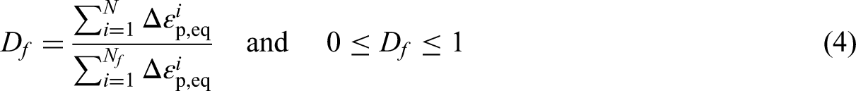
Similarly, the ratchetting ductile damage variable,

The total ductile damage variable, D, is defined as the ratio of the sum of ratchetting ductility exhaustion and fatigue ductility exhaustion to the total final ductility exhaustion (TFDC):
Define the proportional coefficient, g, between the final ratchetting ductility exhaustion and the fatigue ductility exhaustion:
The expression of the total ductile damage variable is derived:

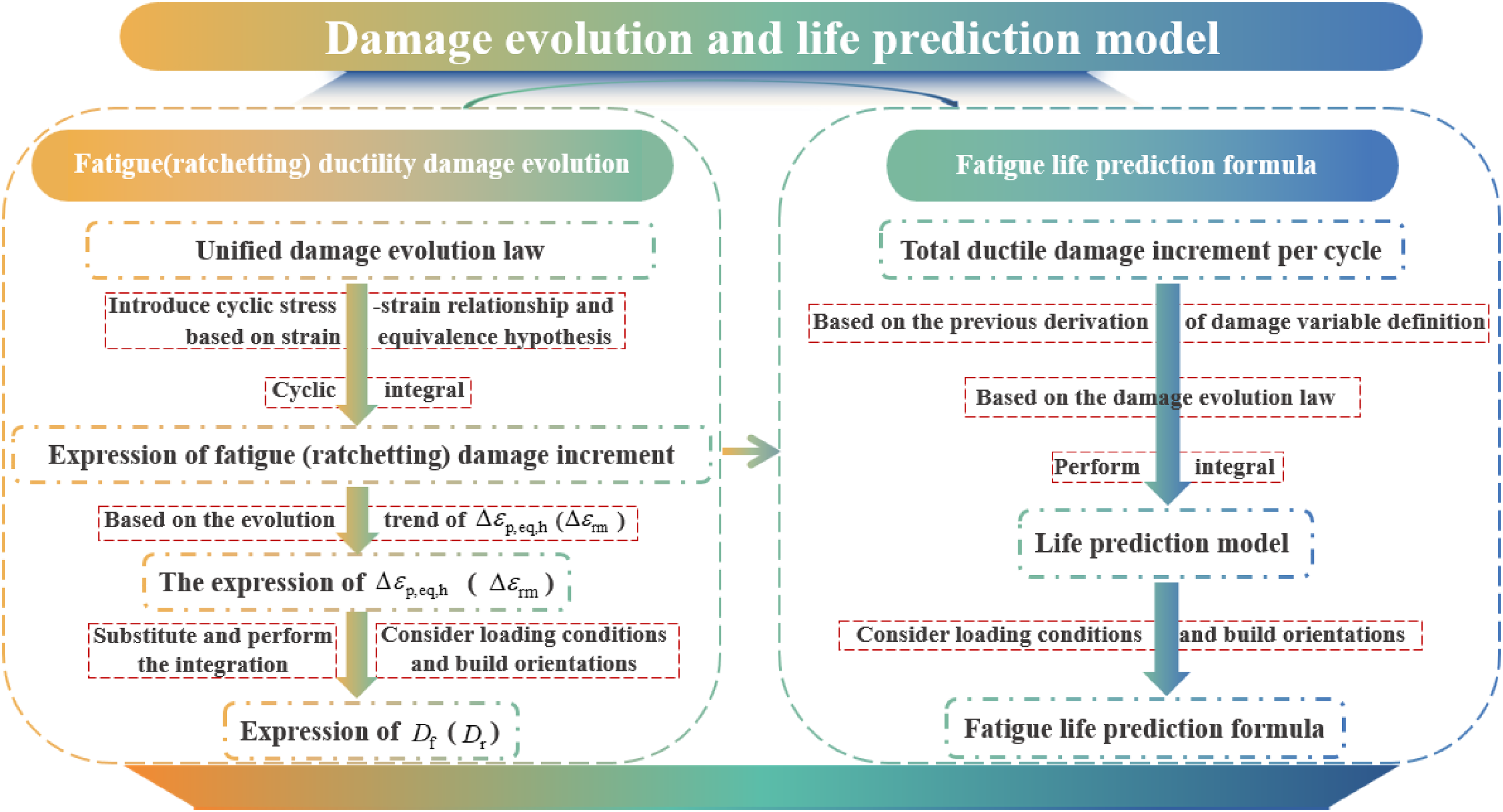
The derivation diagram of equations (1) to (8) is shown in Figure 1. The detailed derivation process is given in Appendix A.
Derivation process of fatigue, ratchetting, and total damage variables based on ductility exhaustion.
To develop a fatigue life prediction model that incorporates anisotropic ratchetting effect, we integrate our previously reported experimental results (Yi et al., 2026) for L-PBF Ti6Al4V specimens fabricated in horizontal build (HB) and vertical build (VB) orientations under asymmetric stress-controlled cyclic loading conditions. The stress–life relationship and schematic illustration of specimens fabricated with VB and HB orientations are shown in Figures 2 and 3, respectively. It is noteworthy that the plastic strain range defined in this work is the maximum width of the hysteresis loop, and the ratchetting strain is the average value of the minimum and maximum strains of each loading cycle. The results indicate that the fatigue life of L-PBF Ti6Al4V alloy depends not only on the stress amplitude and mean stress, but also strongly on the build orientation. Specifically, specimens fabricated in the vertical build orientation exhibit superior fatigue life compared with those fabricated in the HB orientation.
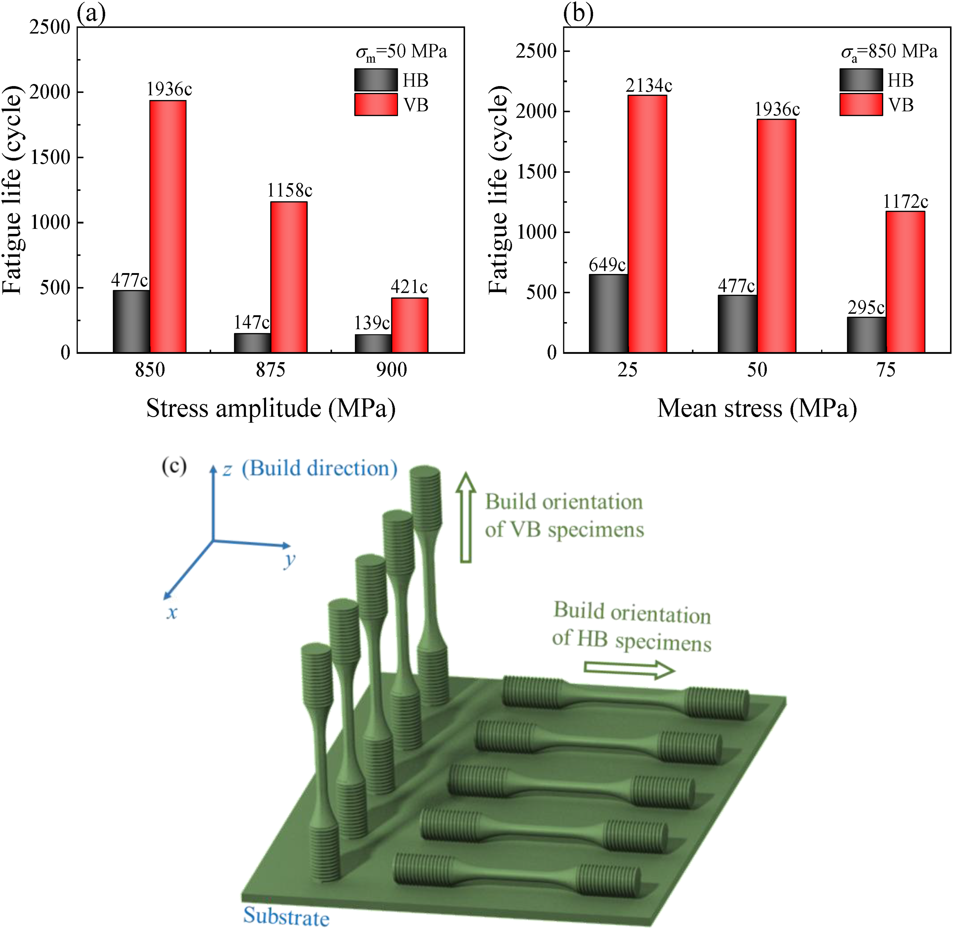
Fatigue life of horizontally built (HB) and vertically built (VB) specimens under different (a) mean stresses and (b) stress amplitudes (“c” stands for “cycle,” representing the number of cycles); (c) schematic illustration of specimens with vertical and horizontal build orientations: vertical build (VB, 90°) specimens, where the loading direction is parallel to the build direction (z-axis), and horizontal build (HB, 0°) specimens, where the loading direction is parallel to the substrate (x–y plane).
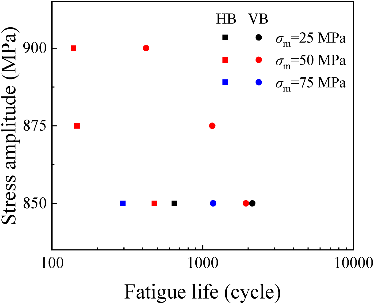
Stress–life relationship of horizontally and vertically built specimens under cyclic loading conditions with mean stresses of 25, 50, and 75 MPa.
Based on the definitions of fatigue ductility exhaustion and ratchetting ductility exhaustion, the former is associated with the cumulative equivalent plastic strain range, which is defined as the accumulated value obtained by converting and summing the plastic strain range over all loading cycles. Although the plastic strain range characterizes the irreversible deformation occurring within an individual cycle, its equivalent measure progressively accumulates with increasing cycle number, thereby representing the gradual accumulation of plastic damage during cyclic loading. In contrast, ratchetting ductility exhaustion is associated with the accumulated ratchetting strain, as defined in equations (1) and (2).
Figure 4 presents the total final ductility exhaustion coefficients, defined as the sum of FFDC and FRDC according to equation (3), for HB and VB specimens under mean stresses of 25, 50, and 75 MPa. For both specimen types, these coefficients remain approximately constant under different loading conditions. This observation supports the rationality of decomposing the total ductility damage variable in equation (3) into fatigue and ratchetting components, and further suggests that fatigue failure occurs when the total ductility exhaustion at the critical crack initiation region reaches a critical threshold.
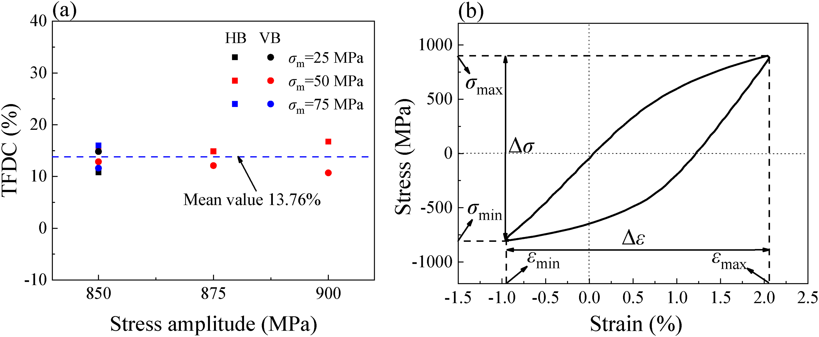
(a) Total final ductility exhaustion coefficient of HB and VB specimens under different mean stresses and stress amplitudes and (b) schematic illustration of a typical stress-strain hysteresis loop used to determine the ratchetting strain and plastic strain range.
To further illustrate the evolution behavior of ductile damage, Figure 5 presents the damage evolution under a representative loading condition (stress amplitude of 850 MPa and mean stress of 75 MPa), based on the damage variables defined in equations (1), (2), and (5). The three curves represent the evolution ratios of the respective damage variables normalized by their cumulative values over the whole fatigue life, allowing qualitative comparison of their relative evolution rates. The results show that fatigue damage dominates during the early stage of cyclic loading, whereas ratchetting damage gradually becomes the predominant damage mechanism in the later stage. This transition highlights the necessity of simultaneously incorporating both fatigue-induced and ratchetting-induced damage mechanisms into the proposed fatigue life prediction framework.
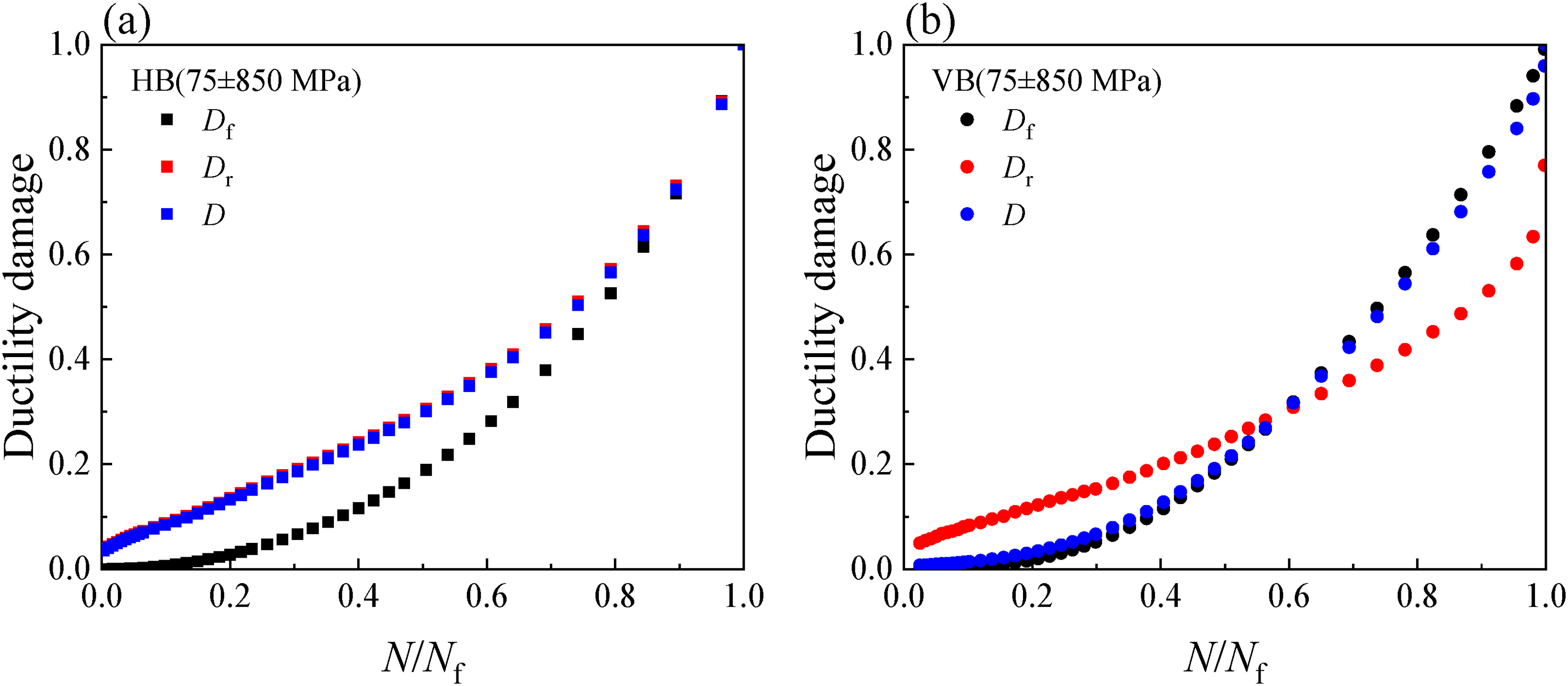
Evolution of the total ductile damage variable D, the fatigue damage component Df, and the ratchetting damage component Dr for (a) HB and (b) VB specimens under a stress amplitude of 850 MPa and a mean stress of 75 MPa.
According to the experimental observations reported by Yi et al. (2026), ratchetting strain accumulates continuously under asymmetric stress-controlled cyclic loading and significantly accelerates fatigue failure. Both the ratchetting strain rate and the final accumulated ratchetting strain increase markedly with increasing stress amplitude and mean stress, thereby promoting faster damage accumulation and reducing fatigue life. Therefore, it is necessary to incorporate ratchetting strain into the damage evolution framework. Furthermore, previous studies (Liu et al., 2010; Luo et al., 2020) have demonstrated that fatigue damage induced by the cyclic plastic strain range and ratchetting damage caused by progressive ratchetting strain are governed by distinct physical mechanisms. The former primarily reflects cyclic plastic deformation behavior, whereas the latter represents creep-like monotonic deformation accumulated during cyclic loading. These two damage components evolve relatively independently and are subsequently superimposed to characterize the total damage state, which is consistent with the physical nature of ratchetting–fatigue interaction.
Strength tensor and orientation characterization
Previous studies (Deng et al., 2025; Yi et al., 2026) have shown that the mechanical properties of L-PBF Ti6Al4V alloy exhibit significant anisotropy. Under asymmetric stress-controlled cyclic loading conditions, VB specimens exhibit higher cyclic yield strength and fatigue strength than HB specimens, thereby resulting in improved resistance to cyclic deformation and longer fatigue life. Therefore, the fatigue life of L-PBF Ti6Al4V alloy is strongly dependent on the build orientation. It is therefore necessary to establish a continuous function that quantitatively characterizes the relative variation of mechanical properties across different build orientations with respect to a reference orientation (i.e. HB), thereby providing a foundation for the development of the fatigue life prediction model.
Based on previous studies (Åkerfeldt et al., 2016; He et al., 2022; Shen et al., 2015), a sine interpolation function is adopted to quantitatively characterize this relationship:

Under the same stress amplitude
To quantitatively characterize the anisotropic cyclic strength associated with different build orientations, a build-orientation tensor
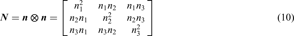
After substituting
Based on the orientation tensor, a second-order cyclic strength tensor is constructed as follows:

The proposed strength tensor is established based on previous experimental observations (Åkerfeldt et al., 2016; He et al., 2022; Shen et al., 2015), which demonstrate that: the yield strength and fatigue performance of L-PBF Ti6Al4V alloy vary with build orientation; under identical asymmetric stress-controlled loading conditions, VB specimens exhibit higher cyclic strength and lower ratchetting strain accumulation than HB specimens; the anisotropic variation trend of fatigue life between VB and HB specimens is consistent with the corresponding anisotropy in cyclic strength.
Based on the constructed orientation tensor, the unit vector at any angle
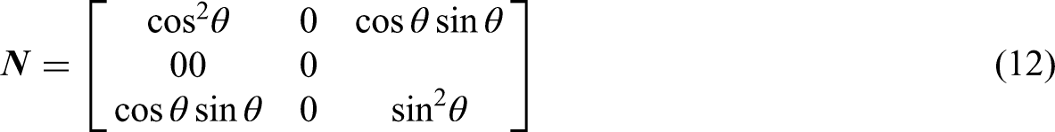
Under uniaxial loading, the orientational weighting can be directly expressed by sinθ and cosθ. The strength tensor can thus be reduced to the scalar projection
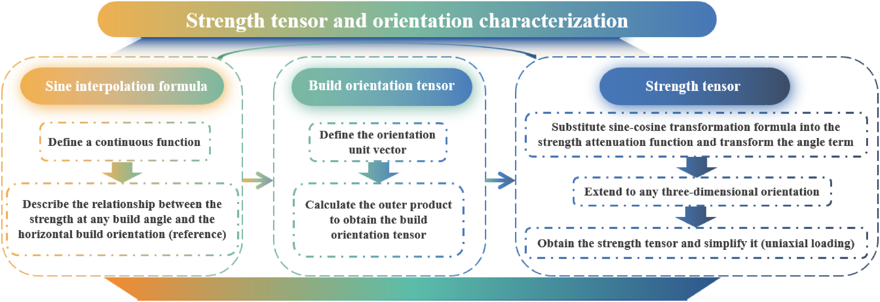
Derivation diagram of the strength tensor and orientation characterization.
The strength tensor established in this study is intended to characterize the physical parameter of cyclic strength, particularly the cyclic yield strength, since it directly governs plastic strain accumulation during ratchetting–fatigue interaction. However, under asymmetric cyclic loading conditions, cyclic strength cannot be independently and directly measured through conventional experiments. Therefore, an indirect calibration strategy is adopted in the present work.
Specifically, the anisotropic characteristics of fatigue strength, represented by the experimentally measurable fatigue life, are utilized to inversely calibrate the anisotropic parameters associated with cyclic strength. Experimentally, VB specimens exhibit longer fatigue life than HB specimens, which reflects the higher cyclic strength of the VB samples. The relationship between cyclic strength and fatigue life is described through the power-law functions associated with the parameters k and Rmax in the proposed model. Based on this correlation, the experimentally observed anisotropy in fatigue life is employed to calibrate the anisotropic evolution of cyclic strength, which is otherwise difficult to directly quantify under asymmetric cyclic loading conditions. Consequently, the proposed model establishes the anisotropic evolution characteristics of cyclic strength through experimentally measured fatigue performance data.
In the present model, the HB (0°) orientation is adopted as the reference orientation for convenience. It is noteworthy that the choice of the HB orientation as the reference state in the proposed model is a matter of convention rather than a physical requirement. In the present framework, the orientation tensor and strength tensor are formulated such that the reference orientation serves only as a baseline for describing relative anisotropy. If an alternative orientation (e.g. 45° or 90°) is selected as the reference, the overall mathematical structure of the model would remain unchanged. Only the associated reference parameters (e.g. cyclic strength coefficients and calibration constants) and the corresponding normalization basis would need to be recalibrated accordingly. Importantly, the predicted fatigue life for any given build orientation relative to another orientation would remain invariant, as the model is constructed to capture relative, rather than absolute, variations in mechanical response with respect to build orientation. Therefore, the capability of the proposed model to characterize anisotropic fatigue life is independent of the specific choice of reference orientation, provided that the reference state is consistently defined during both calibration and prediction.
Damage evolution and life prediction models
Based on the unified damage evolution framework proposed by Lemaitre (Lemaitre and Desmorat, 2005), combined with the cyclic stress–strain relationship (Shen et al., 2015), the strain equivalence assumption (Lemaitre and Desmorat, 2005), and the evolution of the equivalent plastic strain range, a cyclic integration procedure is employed to derive the fatigue damage evolution equations for arbitrary build orientation under various loading conditions as follows:

It is noteworthy that the damage-coupled fatigue life model developed in the present study differs from the approaches adopted by Liu et al. (Liu et al., 2010) and Kang et al. (Kang et al., 2009), in which an elastoplastic cyclic constitutive model, including back-stress evolution and isotropic hardening laws, is first established and subsequently applied to fatigue life prediction. In contrast, the present work adopts a different modeling strategy within the Lemaitre continuum damage mechanics framework, directly establishing the relationship between stress/strain inputs and damage evolution outputs without introducing a complete intermediate constitutive formulation. This simplification is considered reasonable for fatigue life prediction purposes, particularly when reliable cyclic stress–strain experimental data are available.
Similarly, the ratchetting damage evolution equation of any build orientation under various loading conditions is given by:
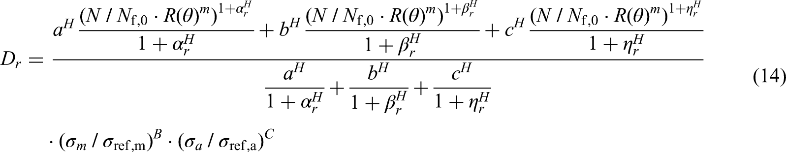
Other parameters are also determined based on the experimental data obtained under the reference condition. B and C represent the sensitivity indexes of the equivalent plastic strain range to the mean stress and the stress amplitude, respectively. Similarly,
Building on the previously defined damage variables and the damage evolution rule, the fatigue life prediction model can be derived:
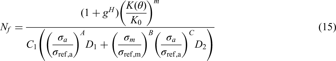
Derivation diagram of damage evolution equations and life prediction models.
Prediction results and discussion
The parameters g,
The determination of remained parameters proceeds as follows. First, a set of experimental data corresponding to a specific loading condition is selected with a mean stress of 50 MPa and a stress amplitude of 850 MPa. Then, based on equations (A9) and (A15), the evolution curves of fatigue ductility damage and ratchetting ductility damage are fitted. Finally, parameter optimization is performed using the nonlinear least squares method, yielding calibrated values for each parameter.
Based on the fatigue ductile damage variable
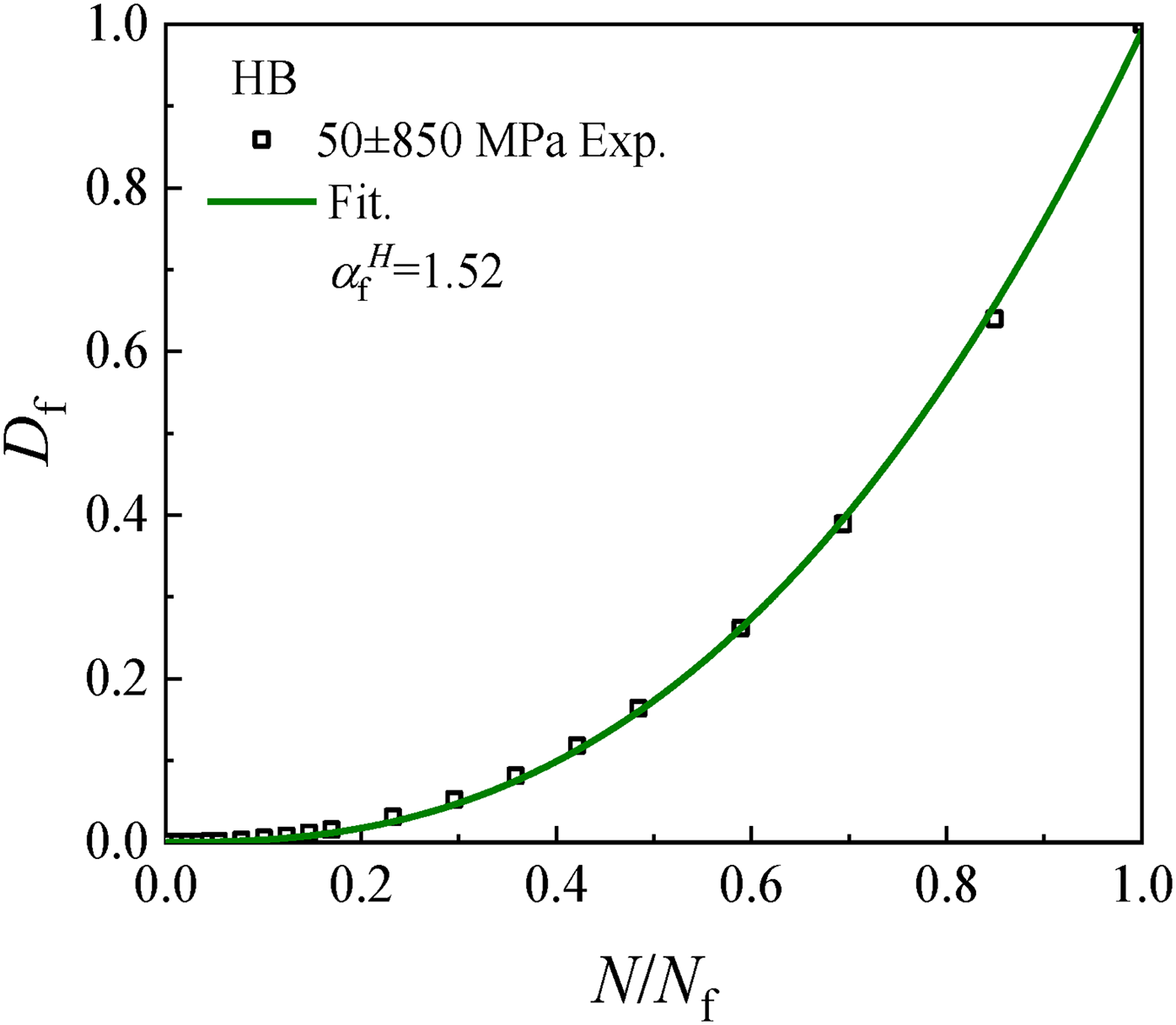
Experimental data and fitted curve of fatigue ductile damage with the number of cycles for the horizontally build (HB) specimen under a loading condition of 50 ± 850 MPa.
According to the ratchetting ductile damage variable
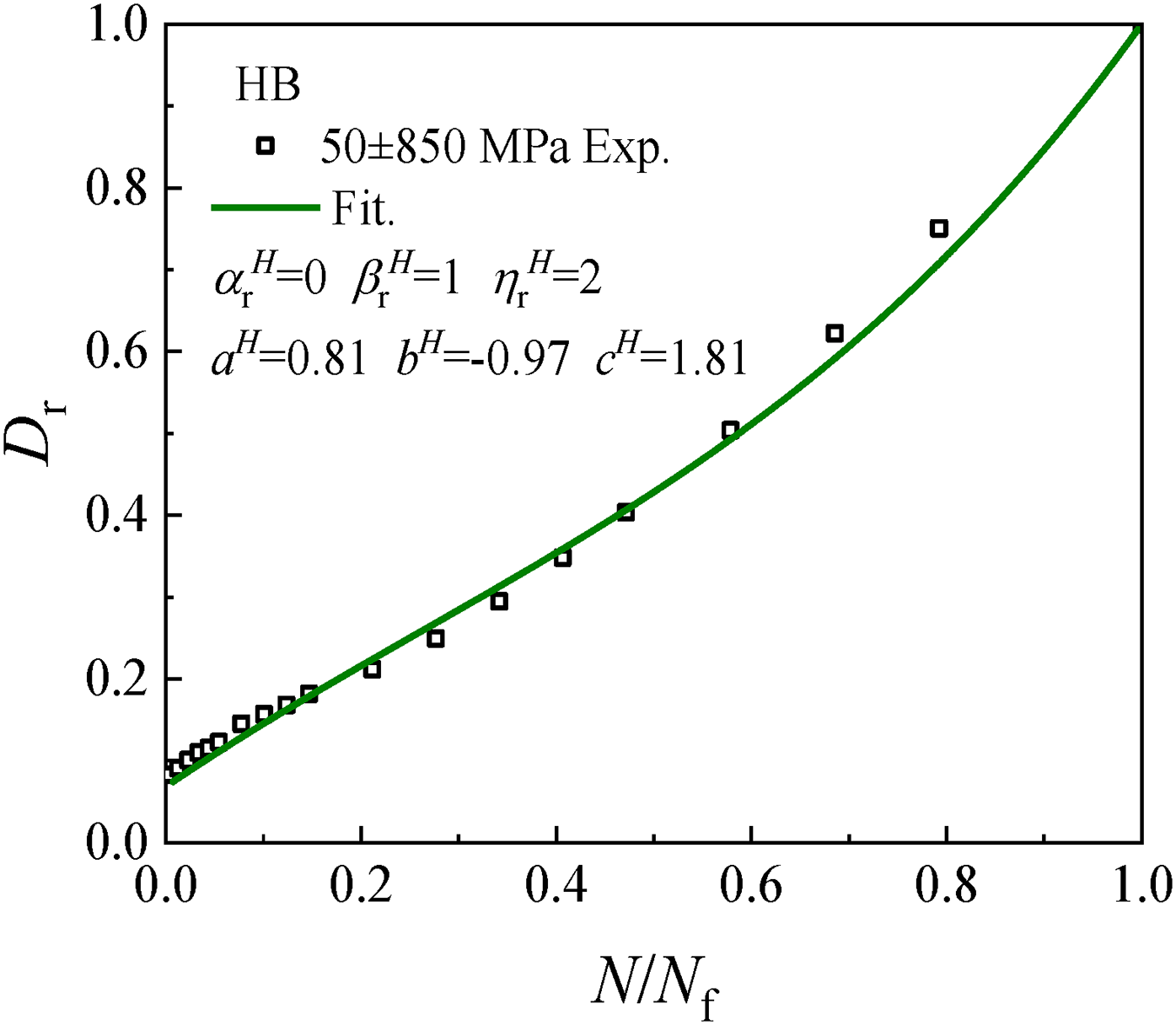
Experimental data and fitted curve of ratchetting ductile damage with the number of cycles for the horizontally build (HB) specimen under a loading condition of 50 ± 850 MPa.
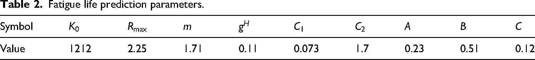
According to the above parameter identification procedure, the obtained parameters are summarized in Tables 1 and 2.
Prediction of fatigue damage evolution: Based on the fatigue damage evolution equation, the fatigue damage evolution curves of VB and HB specimens under different loading conditions are predicted, as shown in Figure 10. The results indicate that the proposed model effectively captures the evolution of fatigue damage with respect to the number of cycles. Further analysis reveals that the predicted curves reproduce the observed damage evolution trends, demonstrating the applicability of the proposed damage model across different loading conditions. A comparison between Figure 10(a) and (b) shows that the model predicts the damage evolution of HB specimens under different conditions with higher accuracy, whereas the predictive accuracy for VB specimens is slightly decreased at high stress levels. Prediction of ratchetting damage evolution: According to the ratchetting damage evolution equation, the ratchetting damage evolution curves of VB and HB specimens under different loading conditions are predicted, as shown in Figure 11. Comparison between the predicted and experimental results demonstrates that the model effectively captures the overall trend of ratchetting damage evolution under most loading conditions, particularly at relatively high stress levels. However, notable discrepancies arise under low mean stress, especially for the 25 ± 850 MPa case, where the simulated damage evolution curve deviates significantly from the experimental trend. Comparative analysis further indicates that the model predicts the ratchetting damage evolution of HB specimens more accurately than that of VB specimens. Prediction of total damage evolution: Based on the damage accumulation rule and the weighting coefficient, the total damage evolution curve is obtained by a weighted superposition of the fatigue and ratchetting damage curves. When
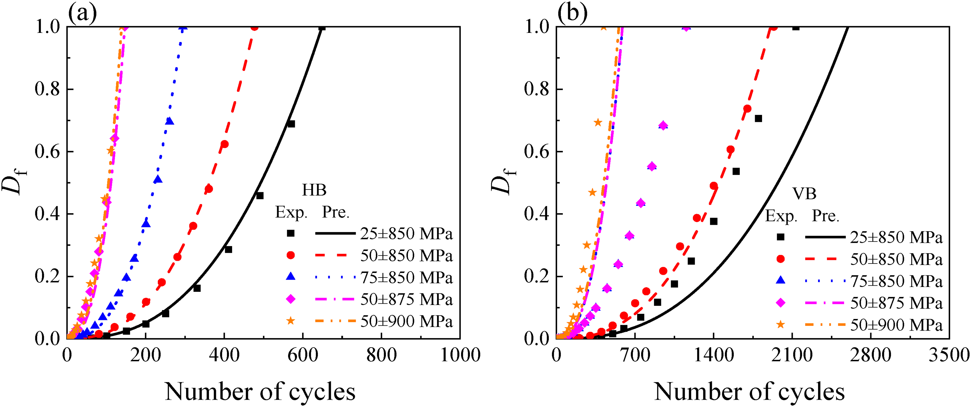
Comparison between predicted and experimental fatigue damage evolution curves for HB and VB specimens under various loading conditions.
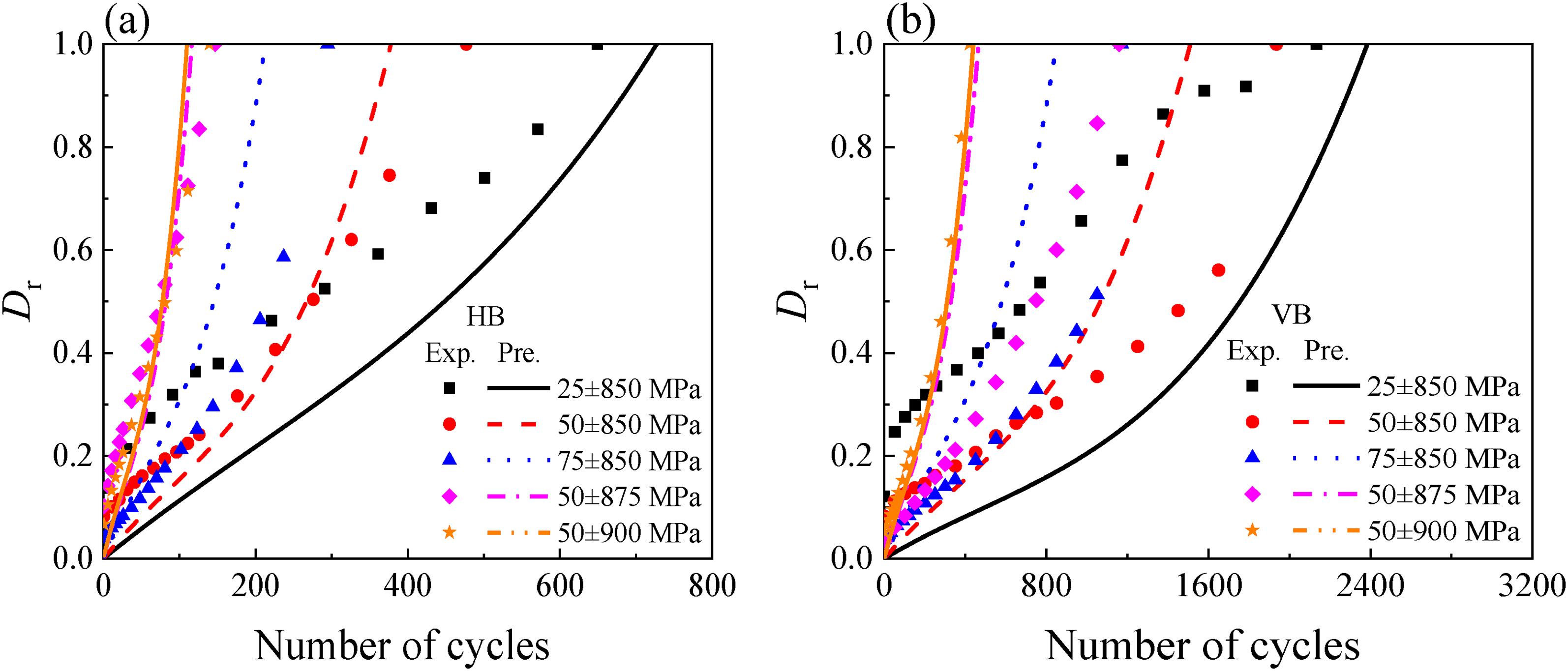
Comparison between predicted and experimental fatigue ratchetting damage evolution curves for HB and VB specimens under various loading conditions.
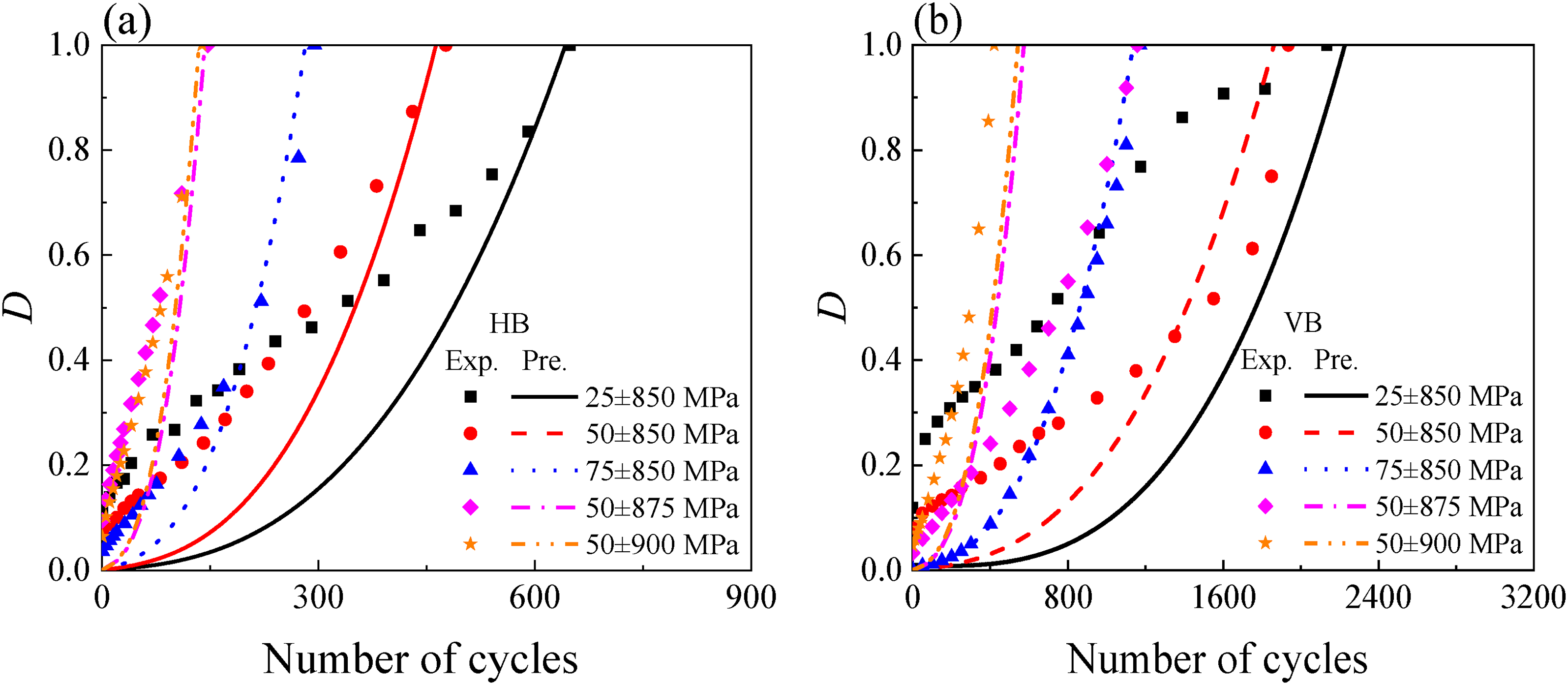
Comparison between predicted and experimental total damage evolution curves for HB and VB specimens under various loading conditions.
Damage evolution parameters.

Fatigue life prediction parameters.
In conclusion, comparison between the experimental and predicted results demonstrates that the proposed damage evolution model can reasonably capture the dependence of damage evolution on both build orientation and loading conditions, while accurately reflecting the overall trend of damage evolution.
Although the proposed model captures the main trends of anisotropic fatigue damage evolution, certain discrepancies between predictions and experiments are observed in Figures 10 to 12, particularly for VB specimens under specific loading conditions. These deviations are attributed to several factors.
First, the evolution of the equivalent plastic strain range with cycles is described using a unified expression (equation (A5)) calibrated primarily from HB specimens, whereas the cyclic softening/hardening behavior differs between HB and VB specimens (Yi et al., 2026). This contributes to overestimation or underestimation of the fatigue damage accumulation rate for VB specimens. Second, the three-stage fitting function for the ratchetting strain rate (equation (A14)) is also calibrated predominantly from HB specimens. Although it captures the general trend, it does not sufficiently describe the stage transition characteristics of VB specimens under asymmetric stress-controlled cyclic loading. In particular, both the stage characteristics and the relative contribution of the ratchetting strain rate vary significantly with stress level (Yi et al., 2026), whereas the model predictions tend to remain relatively smooth and uniform. This discrepancy consequently affects the accuracy of the predicted total damage evolution, especially during the mid-to-late stages of cycling, where the cumulative effect of weighted superposition (equation (8)) amplifies any systematic deviation in the fatigue or ratchetting damage components.
4.Prediction of fatigue life: Using the proposed fatigue life prediction model and the calibrated parameters, the fatigue lives of VB and HB specimens under various loading conditions can be estimated. Figure 13 shows the predicted fatigue lives of HB and VB specimens obtained from the anisotropic life prediction model. The predicted values are in good agreement with the experimental data. Most points fall within a range of 1.5 times error-band, which confirms the validity of the proposed model. 5.Evaluation of model accuracy: To more rigorously evaluate the accuracy of the model, the coefficient of determination
where y is the experimental value, 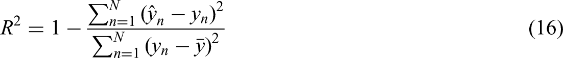
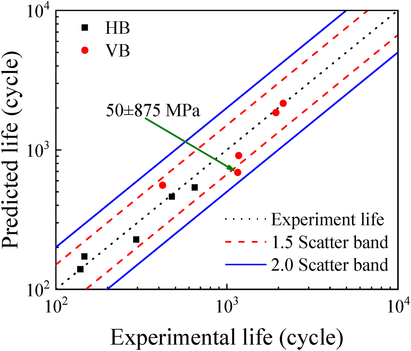
Comparison between experimental results and predictions from the anisotropic fatigue life model.
Table 3 shows the predicted and experimental fatigue lives of the HB and VB specimens. The coefficient of determination
Predicted and experimental fatigue life of VB and HB specimens.
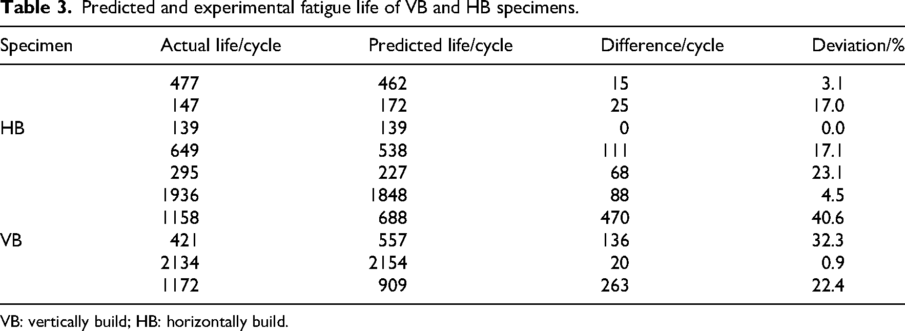
VB: vertically build; HB: horizontally build.
To evaluate the ability of the model to predict the fatigue life of specimens fabricated along different build orientations under different loading conditions, the fatigue life prediction of specimens with different build orientations is drawn by taking different mean stresses as examples. Figure 14 presents the predicted fatigue life distribution of L-PBF Ti6Al4V alloy across a build angle range of 0°–180° under three loading conditions. The three predicted life curves illustrate the nonlinear relationship between build orientation and predicted fatigue life under various mean stresses. The overall trend of the curves indicates that, as the build angle increases from 0° to 90°, the predicted fatigue life exhibits nonlinear growth. These curves show a trend of initially rising sharply and then gradually becoming more stable, indicating that even minor changes in the building orientation can have a significant impact on the fatigue performance. Comparison of the predicted fatigue life curves under the three loading conditions shows that fatigue life varies substantially with stress levels.
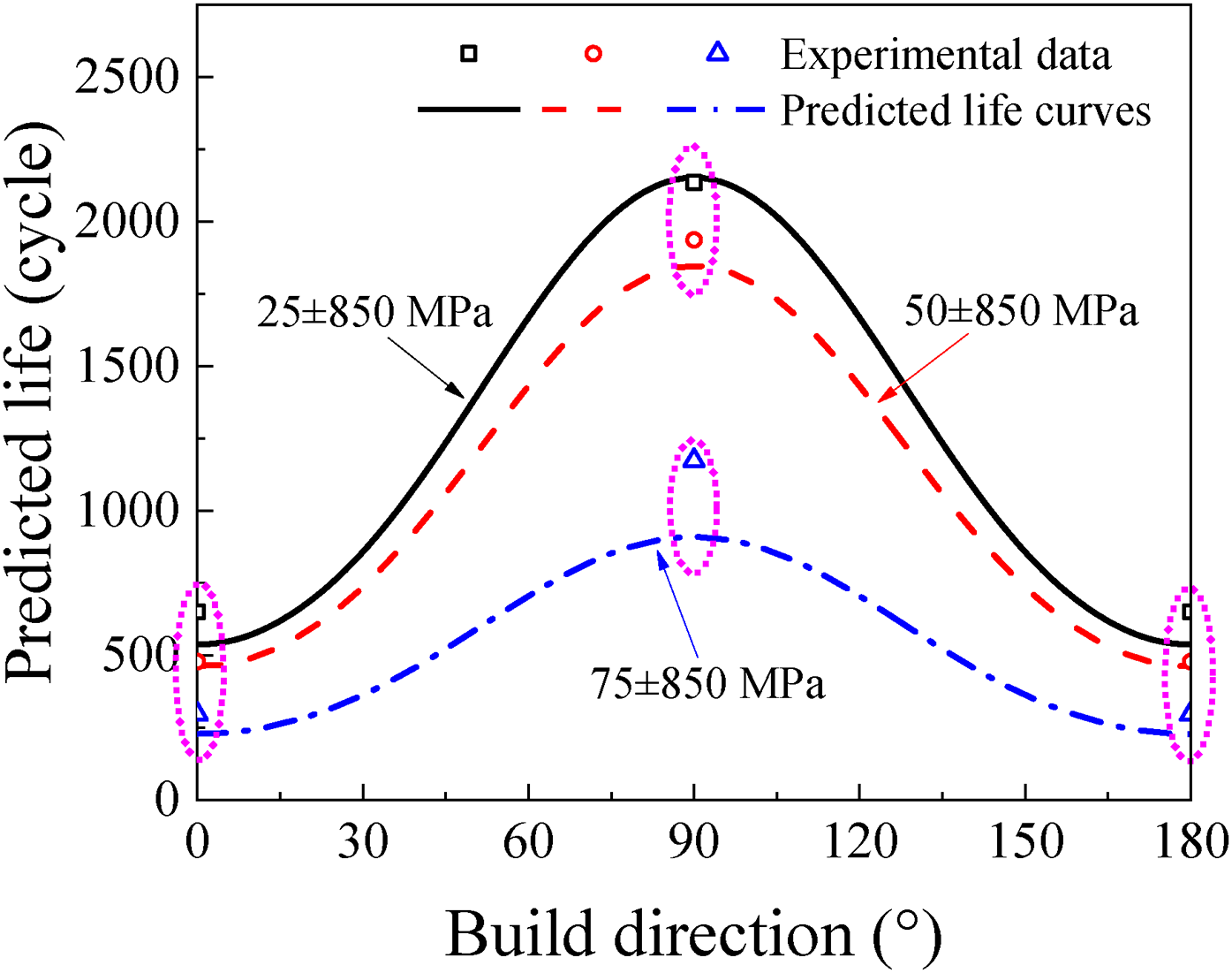
Fatigue life prediction of specimens with different build orientations under different mean stresses.
However, all loading conditions exhibit a consistent nonlinear “build-angle-fatigue-life” relationship, reflecting the fundamental mechanical mechanism by which the anisotropy of the microstructure of the material affects the fatigue performance through the build orientation. Notably, within the 60°–120° build-angle range, the magnitude of fatigue life improvement varies noticeably across different loading conditions. Overall, the proposed model effectively accounts for the combined effects of build orientation and loading conditions and demonstrates good predictive capability based on the available experimental data. Nevertheless, this conclusion requires further validation under additional loading conditions and through more experiments. Future work can enhance the universality and reliability of the proposed model by incorporating extreme loading cases.
It is noteworthy that providing experimental fatigue life data for intermediate build orientations (e.g. 30°, 45°, and 60°) would further strengthen the validation of the proposed anisotropic life prediction model. However, due to practical constraints, including the limited availability of L-PBF fabricated specimens in the initial batch, the inherent batch-to-batch variability in mechanical properties, and the high cost and long duration associated with fatigue testing, such extensive experimental datasets are not currently available. Nevertheless, the current validation is still considered physically meaningful and methodologically sound for the following reasons:
As systematically reported in our previous experimental studies (Deng et al., 2025; Yi et al., 2026) and also confirmed by other researchers (Åkerfeldt et al., 2016; He et al., 2022; Shen et al., 2015), HB and VB specimens exhibit the most pronounced differences in yield strength, cyclic softening behavior, ratchetting strain accumulation, and fatigue life. These two orientations therefore represent the lower and upper bounds of the mechanical response, respectively. The mechanical properties of speciemens with intermediate build orientations are generally expected to fall within these two bounds. Consequently, calibrating and validating the model using these two extreme build orientations provides a conservative and physically consistent basis for interpolation to arbitrary intermediate build angles.
Moreover, the sine-function-based interpolation method (equation (9)) adopted in this study has been successfully validated in existing literature (Åkerfeldt et al., 2016; He et al., 2022; Shen et al., 2015) and captures the essential feature that the influence of build orientation on fatigue life follows a smooth, monotonic transition. As shown in Figure 14, under all three loading conditions, the predicted fatigue life for intermediate orientations (e.g. 45°) falls reasonably between the 0° and 90° bounds. Furthermore, under the reference loading condition (25 ± 850 MPa), the predicted life ratio between the two extreme orientations (HB and VB) is approximately consistent with the experimentally observed ratio reported in our previous study (Yi et al., 2026).
The proposed model provides a deterministic prediction of fatigue life based on mean material properties and the continuum damage mechanics framework. However, as widely reported in the literature (Le et al., 2020; Xiao et al., 2018), additively manufactured metallic materials exhibit significant scatter in fatigue life due to the stochastic nature of manufacturing defects, including variations in defect size, morphology, and spatial distribution. The current model does not explicitly account for this statistical scatter. Therefore, the predicted fatigue life should be interpreted as a mean-life estimate under the given loading and build orientation conditions. For engineering applications that require reliability assessment (e.g. probabilistic design or life prediction with a specified confidence level), a probabilistic extension of the present model is necessary. This could be achieved by incorporating statistical distributions of defect characteristics into the damage evolution law or by employing Monte Carlo simulations based on the calibrated deterministic model. Such an extension is beyond the scope of the present work but represents a valuable direction for future research.
The proposed fatigue life prediction model is developed within the general framework of continuum damage mechanics and ductility exhaustion theory. Its core formulation, including the decomposition of total damage into fatigue and ratchetting components, the use of orientation and strength tensors to describe anisotropy, and the associated damage evolution laws, is not inherently restricted to Ti6Al4V alloy. Therefore, the proposed framework can, in principle, be extended to other additively manufactured metallic materials (e.g. 316L stainless steel; Zhang et al., 2019 and nickel-based superalloy GH4169; Liu et al., 2019), provided that the corresponding material parameters are recalibrated based on experimental data for each target material.
However, several considerations should be noted when applying the model to other materials. First, the specific form of the empirical functions, particularly the three-stage ratchetting strain rate function (equation (A14)) and the sine interpolation function for orientation dependence (equation (9)), was established based on the observed cyclic deformation characteristics of L-PBF Ti6Al4V alloy. For materials with different cyclic softening/hardening behaviors or different patterns of anisotropy (e.g. materials exhibiting tension-compression asymmetry or more complex orientation-dependent properties), these empirical functions may require modification or replacement. Second, the assumption that the two extreme build orientations (0° and 90°) bound the mechanical properties of all intermediate orientations should be verified for the target material. Third, the current model does not account for fatigue life scatter due to the stochastic nature of manufacturing defects, which may be more pronounced in some additively manufactured materials than in others. A probabilistic extension of the model may be necessary for reliability-critical applications.
Conclusions
This work presents a fatigue life prediction model for L-PBF Ti6Al4V alloy that accounts for the anisotropic ratchetting–fatigue interaction, based on the DET and CDM. The main conclusions are summarized as follows:
The proposed model framework explicitly separates the total ductile damage of L-PBF Ti6Al4V into fatigue-driven and ratchetting-driven parts. Their interaction is captured by the proportional coefficient. By comparing the predicted damage evolution curve with the experimental data, it is verified that this decomposition method is reasonable for this material. Based on the damage evolution rules proposed by Lemaitre, the fatigue and ratchetting damage evolution equations are derived. These equations are combined with the cyclic stress-strain response, the evolution of the equivalent plastic strain range, and the nonlinear characteristics of the ratchetting strain rate, thereby forming a comprehensive damage evolution rule. Additionally, a strength tensor with the build orientation is introduced to quantify the strength of specimens fabricated along any build orientation, enabling parameter calibration using experimental data from a single loading condition. The predictive capability and practical applicability of the model are validated. Most fatigue life predictions fall within a factor of 1.5 of the experimental results, and the model accurately captures the damage accumulation trends for both HB and VB specimens. Additionally, this model is capable of establishing a correlation between load conditions, build orientations, and fatigue life, thereby enabling the reliable prediction of fatigue life under different loading conditions.
Footnotes
Acknowledgements
Financial support from the Advanced Materials-National Science and Technology Major Project (2025ZD0611000), National Natural Science Foundation of China (12192210, 12192214, and 12393782), Sichuan Provincial Natural Science Foundation (2025ZNSFSC0008), Independent Project of State Key Laboratory of Rail Transit Vehicle System (2023TPL-T03), and Postdoctoral Fellowship Program of CPSF (GZC20240702) is acknowledged.
Author contributions
Y Yi conducted the fatigue tests, developed the model, and drafted the manuscript. X Xu assisted in model development. XJ Deng and YX Liu assisted with the fatigue experiments. YN Hu, JL Li, QH Kan, and GZ Kang revised the article and approved the version to be published.
Funding
The authors disclosed receipt of the following financial support for the research, authorship, and/or publication of this article: This work was supported by the Postdoctoral Fellowship Program of CPSF, Advanced Materials-National Science and Technology Major Project, Independent Project of State Key Laboratory of Rail Transit Vehicle System, National Natural Science Foundation of China, Sichuan Provincial Natural Science Foundation (grant numbers GZC20240702, 2025ZD0611000, 2023TPL-T03, 12192210, 12192214, 12393782, and 2025ZNSFSC0008).
Declaration of conflicting interests
The authors declared no potential conflicts of interest with respect to the research, authorship, and/or publication of this article.
Data availability statement
The experimental data that support the findings of this study are available by contacting with the corresponding author.