
Abstract
Tamping is the foremost technique used in rock ballast maintenance. With the goal of minimizing tamping-induced degradation of rock ballast and enhancing maintenance effects, a novel tamping method with a smart tamping tine was developed. First, the new tamping machine was designed, allowing automatic toggling between retracted and extended states of the tine structure during tamping. Subsequently, a model of ballasted track subjected to tamping was established and validated against field-measured ballast acceleration data. Using this model, the dynamic responses and mechanical states of rock ballast were analyzed, and the optimal size of the tamping tine was determined. The results showed that the new tamping method could significantly mitigate damage to rock ballast and improve maintenance effects. The maximum improvement in the uniformity index of the rock ballast using the new tamping method reached 182.96% compared with that using the old tamping machine. The optimal width and height of the tine structure for the new tamping method were 60–70 and 75–80 mm, respectively.
Introduction
Ballasted tracks are among the critical structures for supporting train operation (Cai et al., 2024; Dimitrovová, 2022). However, the ballast inevitably degrades under cyclic train loads, resulting in geometric irregularities of track, hardening of rock ballast, and disengaging of the sleeper (Chen et al., 2022; Ferro et al., 2022; Koohmishi et al., 2024). Tamping constitutes the foremost approach to solving these problems and maintaining a ballasted track. Nevertheless, tamping could cause an intense impact on the ballast and disrupt the ballast aggregate (Guo et al., 2021). Hence, researchers have studied the ballast damage and maintenance effects on the ballast bed owing to tamping.
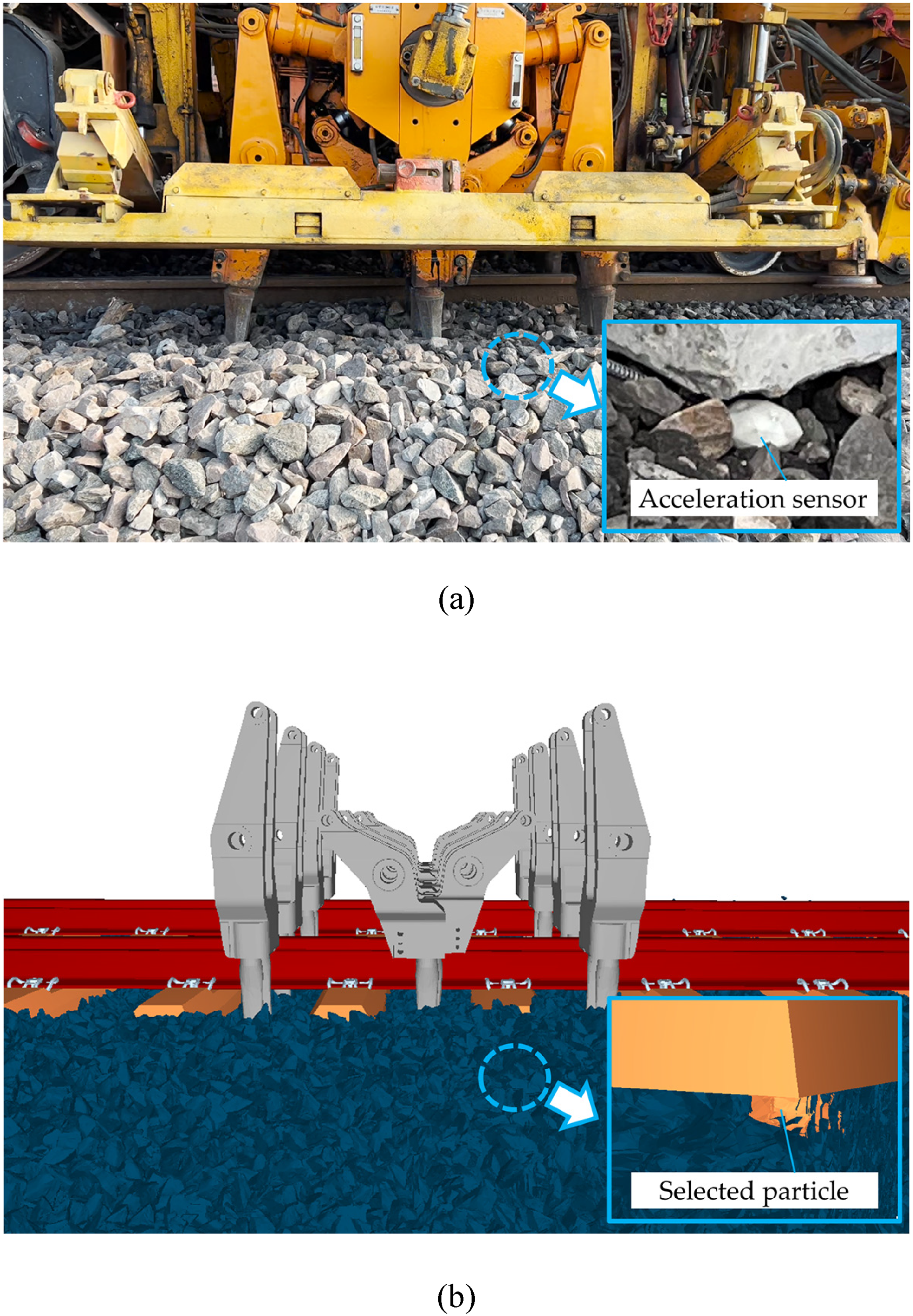
Previous studies have centered on the mechanical response of ballast and have examined damage resulting from tamping. Zhou et al. (2024) tested ballast acceleration and stress on ballast during tamping in the field. They ascertained the correlation between tamping parameters and the resultant mechanical behavior of particles. Chen et al. (2025) and Wang et al. (2024) analyzed the vibration characteristics of ballast during the tamping operation employing the discrete element method (DEM). The results demonstrated that ballast aggregate was severely disturbed during the insertion of tamping. Chi et al. (2024) explored the force and energy of particles in tamping operation utilizing DEM. They found that ballast particles were adversely affected at the end of insertion due to significant contact forces. Shi et al. (2021) constructed a tamping model with breakage ballast particles using the DEM and studied ballast breaking during tamping operation. They found that the ballast particles between sleepers were the most easily crushed. Therefore, tamping can cause severe damage to ballast particles during tamping insertion, as shown in Figure 1. It is imperative to prioritize this issue.
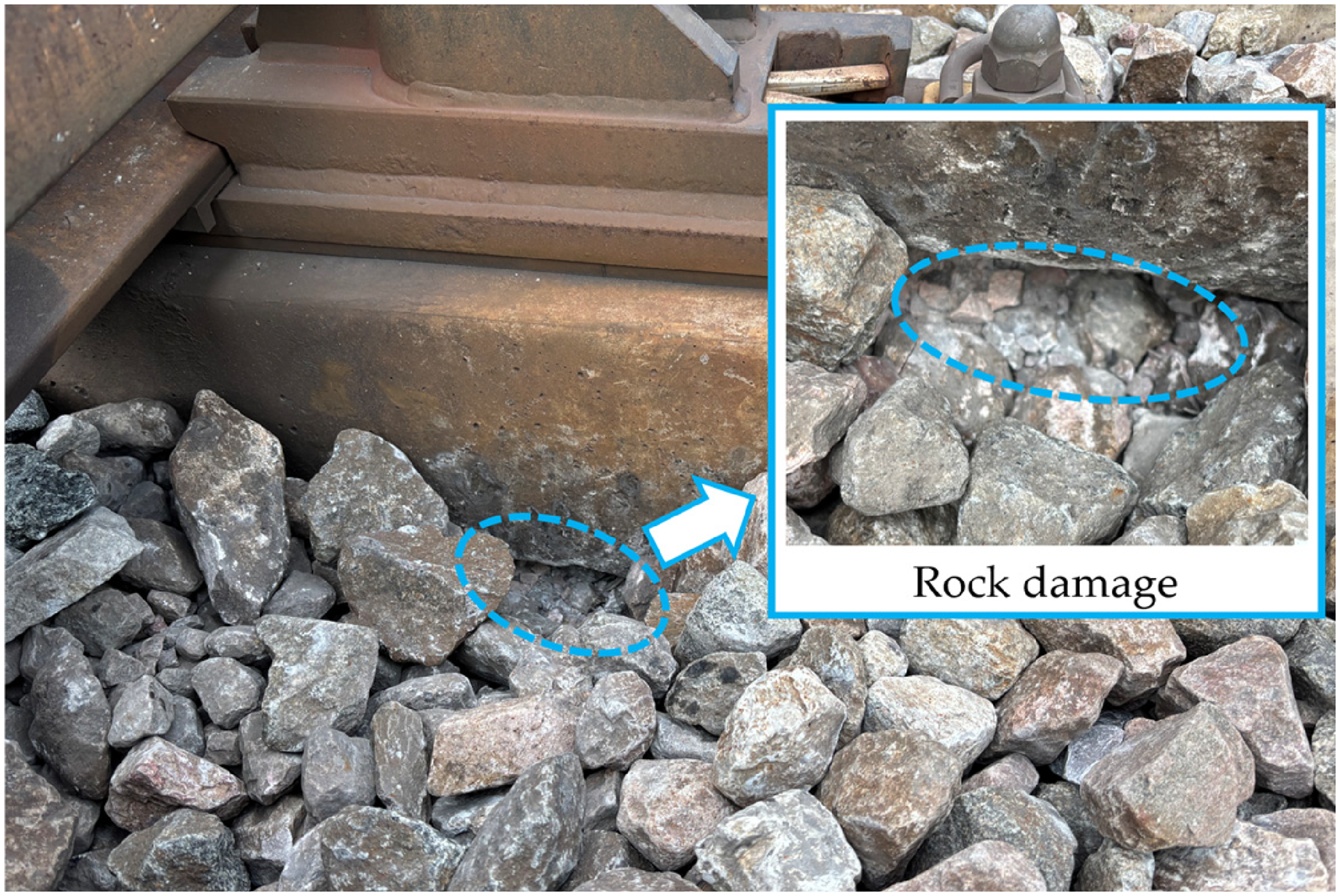
Tamping-induced damage of rock ballast.
Research by several scholars has centered on the mechanical state of the ballast bed and the assessment of tamping maintenance effects. Abbasi et al. (2024) and Pereira et al. (2025) assessed the bearing capacity of the track structure subsequent to field tamping. They ascertained the maintenance effects over a series of tamping operations. Aingaran et al. (2018) and Sol-Sánchez et al. (2016) measured ballast settlement in laboratory. They explored the change of resilient modulus of ballast owing to tamping. Kumara et al. (2016) captured ballast bed deformation using a camera in laboratory and evaluated the condition of discrete particles after tamping. Shi et al. (2020) explored the spatial multi-axial resistance of a ballast structure after maintenance operation using DEM. Przybyłowicz et al. (2022) evaluated the maintenance effects of the side and vertical tamping operations on a ballast structure using DEM. Kim et al. (2018) and Qian et al. (2024) investigated the contact states between ballast and sleeper using the DEM. They optimized the tamping mode according to the maintenance effects. Summarily, the tamping parameters and modes were optimized to enhance ballast bed maintenance effects. However, even optimized tamping operations still induce damage to the ballast and fail to deliver satisfactory maintenance outcomes, due to conflicting size requirements across different tamping stages. Hence, the design of the tamping machine, mainly the tine size, has a significant effect (Offenbacher et al., 2021).
With the objective of mitigating rock ballast damage and enhancing maintenance outcomes, a novel tamping method was developed in this study. First, a new tamping machine with an adjustable tamping tine was designed. Subsequently, a tamping-ballasted track model was constructed utilizing DEM and multi-body dynamics (MBD), verified through a comparison with the tested acceleration in the field. Utilizing this model, the mechanical response of rock ballast and the maintenance effects on ballast bed using old and new tamping machines were analyzed. On this basis, the optimal tine size applied to the new tamping method was determined. This study provides practical guidance for the valuable renewal of tamping machines.
Simulation model
New tamping method
In this section, a new tamping method with an adjustable tamping tine was developed. Based on this, a model of the new tamping machine with different sizes was established using the MBD.
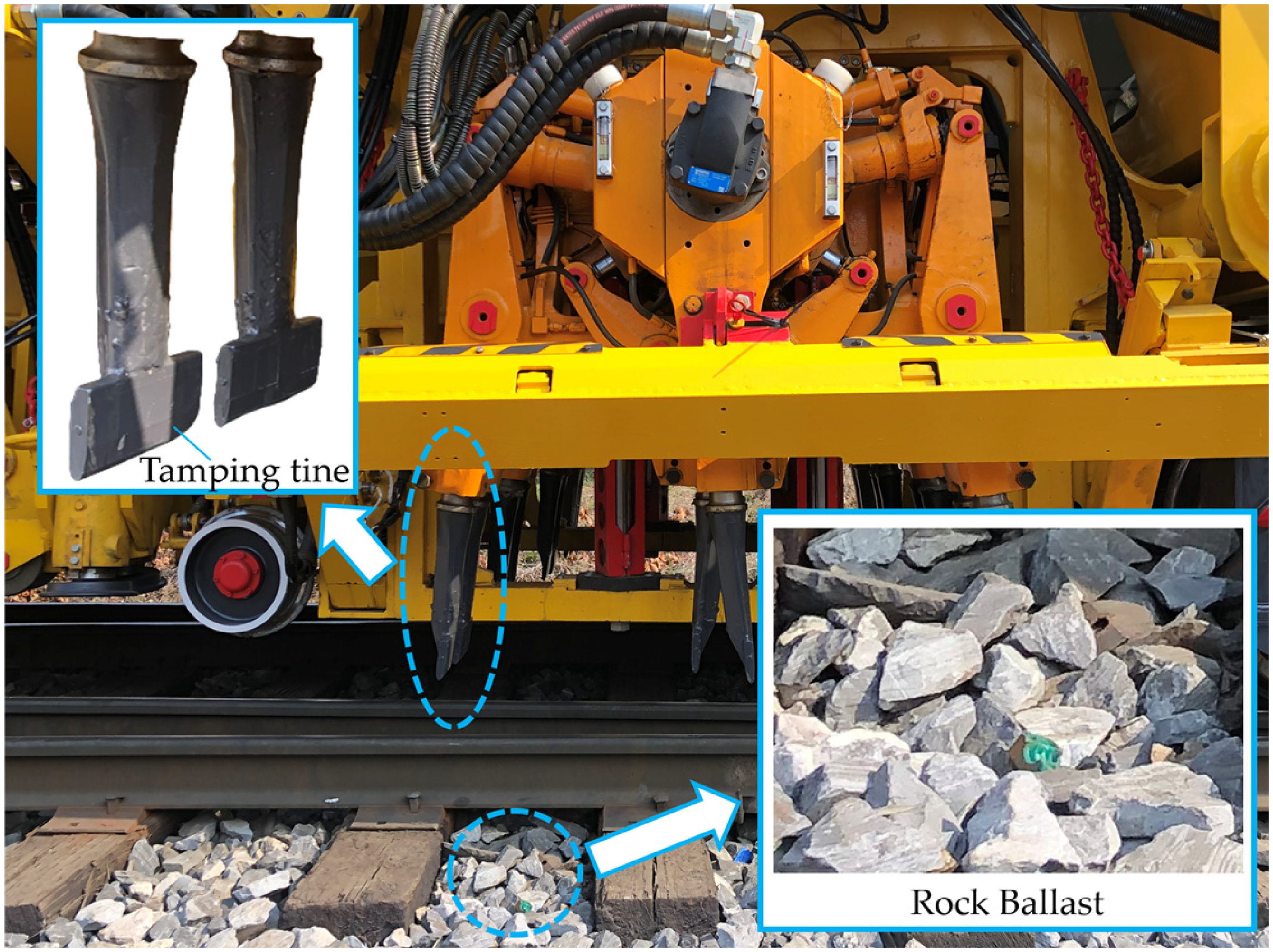
The conventional tamping method currently employed worldwide is illustrated in Figure 2. The tamping machine features a fixed tine, the size of which significantly influences performance. When the tamping tine is large, substantial damage is inflicted on the crib ballast during the insertion stage, and ballast disturbance is further exacerbated during withdrawal. Conversely, a small tamping tine fails to adequately compact ballast into the voids beneath the sleeper, leading to suboptimal maintenance outcomes. Therefore, the tine size plays a crucial role. To simultaneously achieve the least damage to the ballast and the most considerable maintenance effects on the ballast bed, different sizes of tamping tine at different stages are required.
Old tamping method currently used in the world.
The new and old tamping machines are compared in Figure 3. The essential difference lies in the fact that the tamping tines of the old tamping machine have fixed sizes, whereas those of the newly developed tamping machine can be automatically adjusted during operation. Figure 3(b) illustrates the schematic of the design for new tamping machine. A hydraulic controller was added to the top of the tamper and was connected to the tamping tine through an oil pipe. The tamping tine is a key component of the newly designed tamping machine. Two movable wing plates were placed on the two sides of the tamping tine. They were connected and controlled using a piston rod. When the tamping tine was extending, the oil in the hydraulic controller was transferred to the oil chamber through the oil pipe and injection hole. This can provide a sufficient extending force acting on the wing plates through the piston rod; thus, the tamping tine can finally reach the extended state. Conversely, when the tamping tine was retracting, the oil in the oil chamber flowed back into the hydraulic controller. This can provide an adequate retraction force acting on the wing plates through the piston rod, and the tamping tine can finally achieve the retracted state. Notably, the tamping tines experience substantial loading during maintenance operation and exhibit a relatively short service life. Therefore, high-strength steel is required for the manufacture of this component. Summarily, the newly designed tamping tine can adaptively change its state during tamping operations. Specifically, it remains in a retracted state with a reduced tine profile during the insertion and withdrawal stages, thereby minimizing damage to the ballast. In contrast, during the squeezing stage, the tine extends to an enlarged size, which improves track consolidation and enhances maintenance outcomes. This innovative functionality effectively addresses the practical limitations associated with conventional tamping methods.
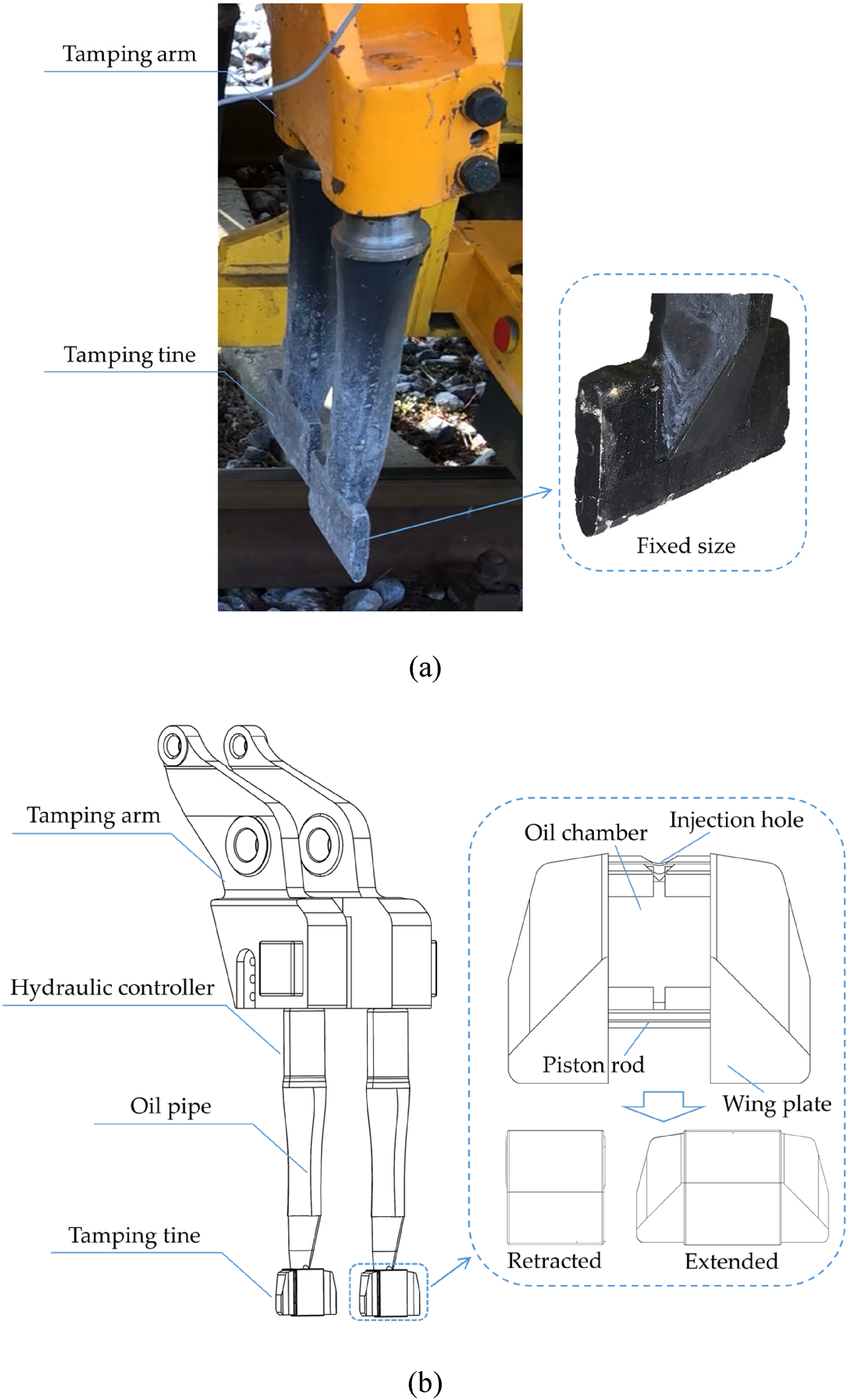
Comparison between the structures of old and new tamping machines: (a) old tamping tine with fixed size and (b) new tamping tine with adjustable size.
The new tamping machine was made of steel, which is a rigid body; hence, its model was established using the MBD according to the design sketch, as presented in Figure 4. Figure 4(a) and (b) illustrate the retracted and extended states of the new tamping machine model, respectively. The two states undergo interconversion during tamping. Additionally, the tine size significantly influences tamping effects on the ballast bed. Hence, new tamping machines with different sizes of tamping tines were constructed, with widths ranging from 50 to 90 mm and heights ranging from 70 to 90 mm. For the tamping machine system in MBD, the global equations of motion were established by computing the relative displacements between nodal points. Two adjacent nodes discretized from the continuum were selected, and the position vectors of the nodes in the inertial coordinate system were determined from the nodal position vectors and the relative deformation. Subsequently, based on the principle of virtual displacement, the recurrence relation for the virtual displacements of adjacent nodes was derived. Finally, by performing iterative calculations along a specified path and incorporating the Euler-Lagrange equations, the system motion was obtained.
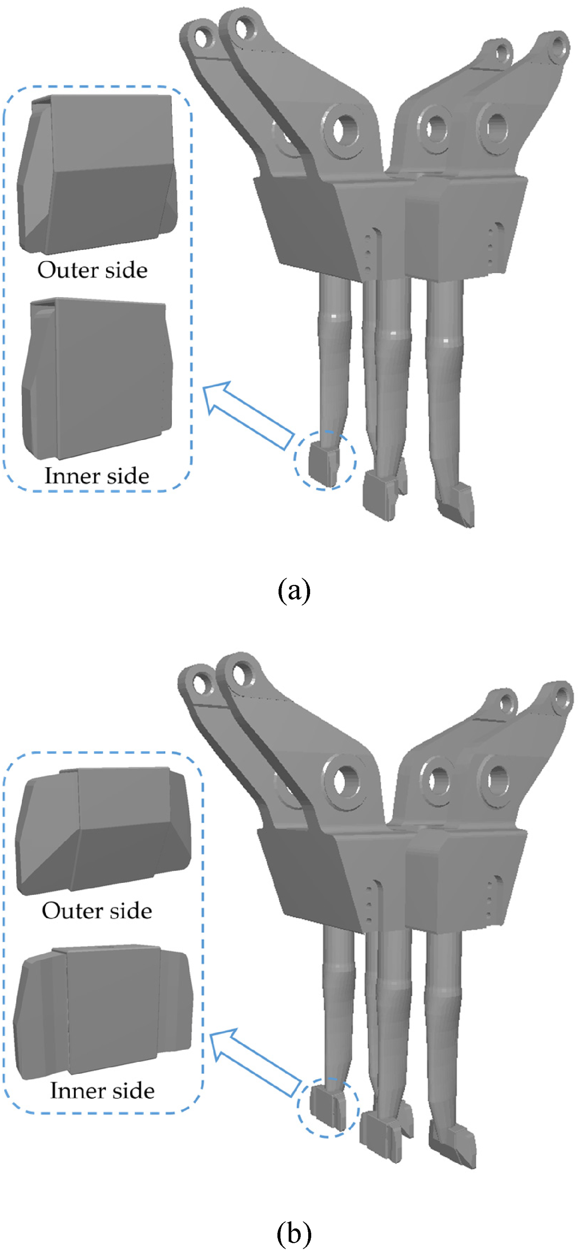
Model of the newly designed structure of the tamping machine with different states: (a) tamping tine retracted and (b) tamping tine extended.
In summary, the new tamping method effectively overcomes the shortcomings of the old tamping methods. The design employs an active variable size to optimize the tine-ballast interface mechanics across different operational stages. During the insertion and withdrawal stages, the retracted profile minimizes the projected contact area, which significantly reduces the penetration resistance and the normal stress exerted on the ballast grains, thereby preventing particle crushing. Conversely, in the squeezing stage, the hydraulic-piston actuation expands the wing plates to maximize the effective working surface. This adaptive synergy between hydraulic control and geometric configuration ensures high maintenance efficiency while preserving the structural integrity of the ballast.
Tamping-ballasted track model
In this section, a model of ballasted track subjected to tamping was constructed. Additionally, the operating procedure of a new tamping method was analyzed.
The ballasted track comprises discrete ballast and continuum parts. Hence, the ballast was modeled by a clump of multi sphere elements with different radius using the DEM (Alabbasi and Hussein, 2021; Ngo and Indraratna, 2020; Tolomeo and McDowell, 2022a). This model captures the actual shape of ballast and the contacts between ballast particles (Chen et al., 2024; Tolomeo and McDowell, 2022b). Additionally, the rail, fastener, and sleeper models were established utilizing MBD (Fang et al., 2023; Liu et al., 2021; Shi et al., 2024). Based on this, a series of ballast models exhibiting distinct shapes, such as cuboid, elongated, and flaky, were developed. Subsequently, these ballast models were integrated with the rail, fastener, and sleeper models to form a complete system. Then, a rigid body was generated on top of the ballast aggregate, and it moved downward to compact the granular assembly. The motion ceased once the geometry and gradation met the corresponding standards (Code for design of high speed railway[S]. Beijing: China Railway Publishing House, 2017). The rigid body remained stationary until the aggregate reached a stable state. Thereafter, the rigid body was gradually retracted upward and removed, thus completing the development of the ballasted track model. The interactions among aggregates and between ballasted track layers were calculated using the Hertz–Mindlin theory, as described by Eqs. (1) and (2), respectively. Ultimately, the old and new tamping machine models were combined with the ballasted track model, as presented in Figure 5. The corresponding parameters are provided in Table 1 (Wanga et al., 2025; Yang et al., 2023; R. Zhou et al., 2024).


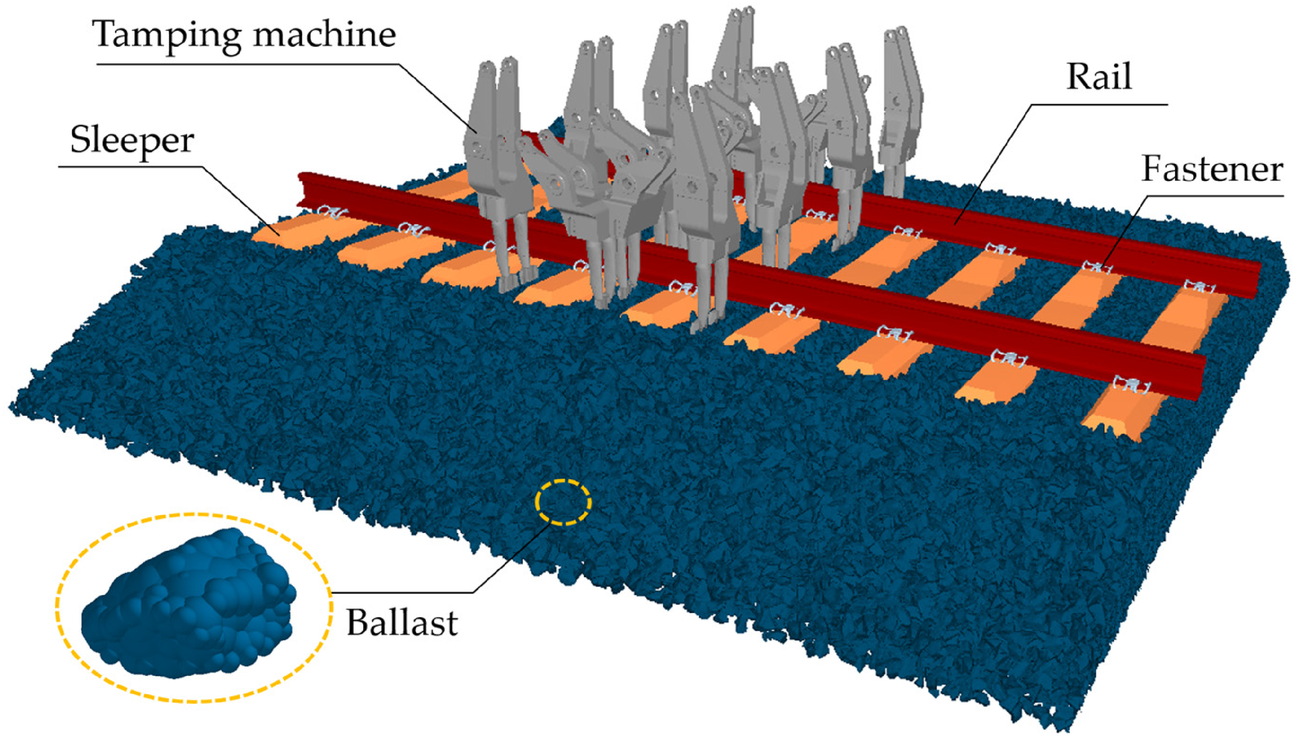
Model of ballasted track subjected to tamping using old/new methods.
Model parameters.
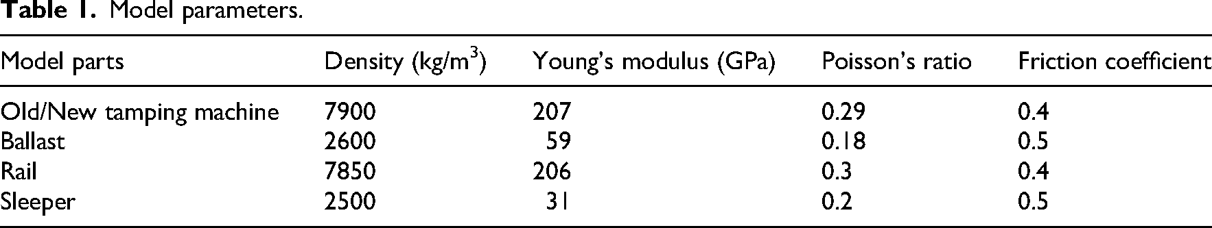
The loading procedure for the new tamping method in the DEM model is illustrated in Figure 6. In the first inserting stage (0–0.3 s), the sleeper was lifted to the desired height, and a new tamping machine with the retracted tine was inserted at a constant velocity under linear motion constraints until the target depth was reached. Then, in the tine extending stage (0.3–0.5 s), the tamping tine was extended to its widest state. In the squeezing stage (0.5–1.1 s), a rotation constraint is imposed on the tamping machine, and the ballast particles are squeezed by the extended tine. Subsequently, in the tine retracting stage (1.1–1.3 s), the tamping tine was retracted to its narrowest state. In the next rotational withdraw stage (1.3–1.7 s), the tamping machine with the retracted tine rotated to its vertical state. Finally, in the linear withdrawal stage (1.7–2.0 s), the tamping machine with the retracted tine was lifted and left the ballast bed.
Tamping loading process using the new tamping method.
In summary, when the new tamping machine was inserted and withdrawn, the tamping tine was in the retracted state with a narrow size; thus, the new tamping method causes slight damage to the ballast bed. When the new tamping machine was being squeezed, the tamping tine was in the extended state with a wide size; thus, the new tamping method facilitates optimal performance in ballast bed maintenance.
Model validation
The ballast vibration reveals the mechanical response of ballast and determines the maintenance effects (Cui et al., 2024; Heydari et al., 2024). Hence, the simulated accelerations of ballast underneath the sleeper during tamping were compared with field test results, thereby validating the constructed model.
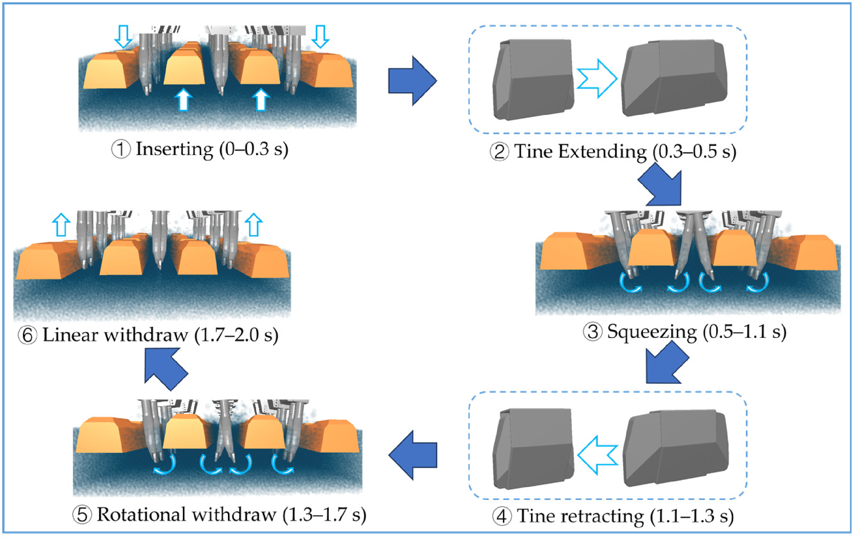
A field test for ballast acceleration during tamping is depicted in Figure 7(a). Before tamping, a sleeper was randomly selected, and the ballast particles adjacent to one side of it were removed. Subsequently, an acceleration sensor with 0.001 m/s2 accuracy was placed underneath the sleeper, as shown in the enlarged view of Figure 7(a). This acceleration sensor was purpose-built to closely mimic the morphology of an actual ballast particle; thus, the actual contacts between discrete particles can be revealed. Additionally, a data acquisition unit was mounted on the outer side of the ballast bed and connected to the acceleration sensor via an armored cable. The data acquisition unit was operated via a laptop, enabling real-time collection and display of the test results. Subsequently, the space around the sleeper was backfilled with the removed ballast particles. Finally, the tamping machine operated on the track, and the particle vibration was measured using the acceleration sensor. To facilitate comparison, the ballast acceleration was extracted from the simulation model, as illustrated in Figure 7(b). Specifically, a ballast particle located at the corner of the middle sleeper was selected to ensure that the monitoring location in the simulation remained consistent with that of the field test. This particle was tracked throughout the entire tamping process to record its acceleration response.
Test for the acceleration of a particle underneath the sleeper during tamping operation: (a) field test and (b) simulation model.
The particle accelerations are compared in Figure 8. The variation regularity of the ballast acceleration in the simulation was similar to that in the field test. The ballast accelerations obtained from both experimental and simulated results displayed minor variations during the machine's insertion and withdrawal intervals, i.e., 0–0.3 s and 0.9–1.5 s, respectively. Conversely, a substantial increase in acceleration was observed during the squeezing stage, i.e., 0.3–0.9 s. Peak magnitudes occurred at approximately 0.75 s, coinciding with the moment the tamping tine reached its close proximity to the acceleration sensor. The peak values of both positive and negative ballast accelerations are summarized in Table 2. The magnitude of positive ballast acceleration during tamping was 871.39 mm/s2 in the simulation, while it was 839.12 mm/s2 in the field test, differing by 3.84%. Additionally, the magnitude of the negative ballast acceleration during tamping was −781.78 mm/s2 in the simulation, while it was −815.67 mm/s2 in the field test, differing by 4.16%. Hence, the difference rates in the magnitudes of positive and negative ballast accelerations were both less than 5%.
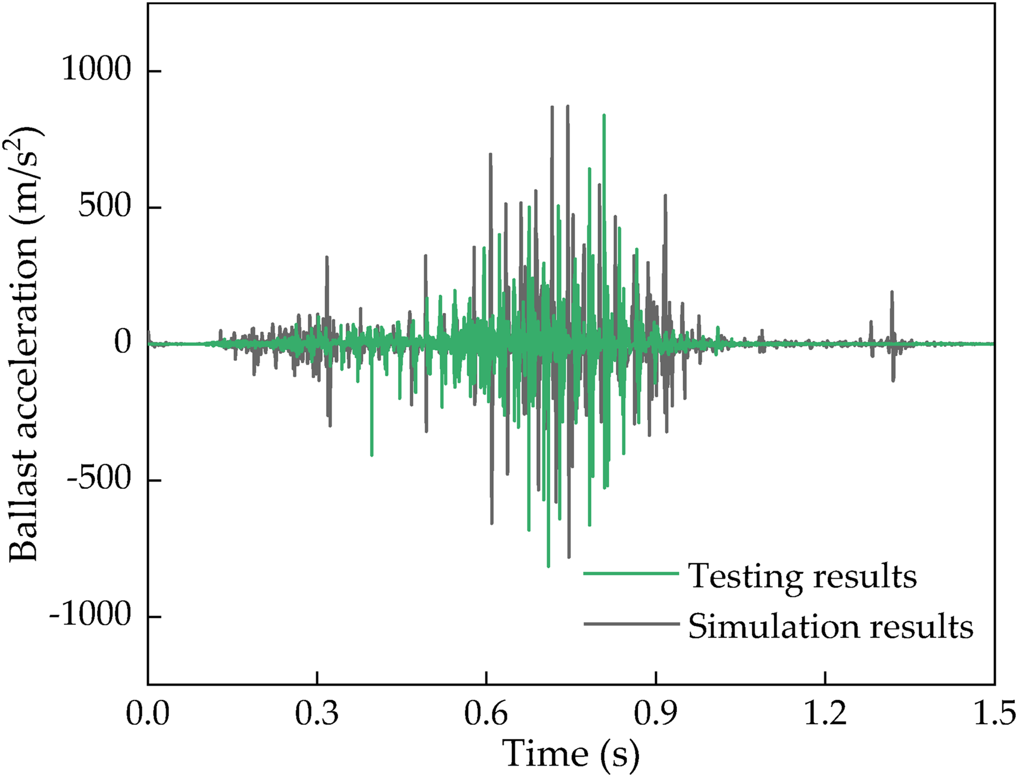
Ballast accelerations in testing and simulation results.
Comparison of ballast acceleration.
In summary, the vibration of the ballast during tamping in simulation correlated well with the field measurements. Therefore, the established model and dynamic solving method exhibited high accuracy.
Results and discussion
Mechanical responses of rock ballast particles
Previous studies have proven that a significant positive correlation exists between the mechanical responses of ballast, including contact force, velocity, and angular velocity, and the resulting ballast damage. Specifically, more pronounced mechanical responses indicate more severe damage to the ballast particles. Consequently, these mechanical indicators have been widely utilized to evaluate ballast damage in the field of railway engineering (Liu et al., 2022; Luo et al., 2025; Shi et al., 2025); hence, they are analyzed in this section.
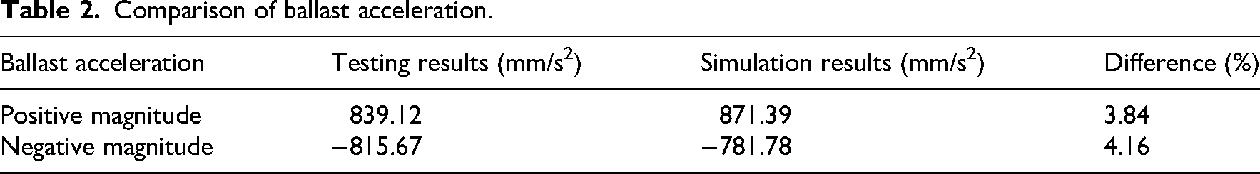
The greatest mechanical extremes during tamping occur in the ballast surrounding the tamping tine at the final insertion moment (Shi et al., 2021); hence, this area is selected, and the corresponding average value of total contact forces on ballast in tamping is illustrated in Figure 9(a). The force acting rises steeply during the insertion and reaches the maximum for the old tamping machine. Following the insertion of the tamping machine, the tamping tine extends. In this stage, the force first decreases sharply for all tamping machines, and then the force increases for the new tamping machines, especially for the 70–90 mm width and 80–90 mm height. This is owing to the fact that the tine extending causes more ballast particles to interact with it. The force peaks upon completion of the tine extending for the new tamping machine with a width of 90 mm and height of 90 mm.
Average contact force on ballast in unfavorable area: (a) temporal evolution of average contact force during tamping and (b) comparison of maximum values.
Figure 9(b) compares the peak values of the average contact forces. The maximum force acting on ballast for the old tamping machine, that is, 1524.79 N, is considerably higher than that for the new tamping machine. This demonstrates that the new tamping machine can significantly reduce ballast degradation compared with the old tamping machine. The maximum values are similar for the new tamping machines with 50–80 mm width and 70–85 mm height, ranging from 678.21 N to 842.29 N, decreasing by 44.76%–55.52% compared with the old tamping machine. Additionally, ballast particles are susceptible to crushing when the corresponding contact force exceeds 10 kN. Consequently, the proportion of particles subjected to contact forces greater than 10 kN is commonly adopted as a damage index. The measured damage index is 0.51% for the old tamping machine, while it is 0.19% for the new tamping machine with 50 mm width and 70 mm height, representing a reduction of 62.75%. These results confirm the significant effectiveness of the new tamping machine in reducing ballast degradation. The maximum average contact force for the new tamping machine with 90 mm width and 90 mm height, that is, 1091.88 N, is 47.59% higher than that for the new tamping machine with 80 mm width and 85 mm height, indicating that the excessive size of the tamping tine is unfavorable for ballast.
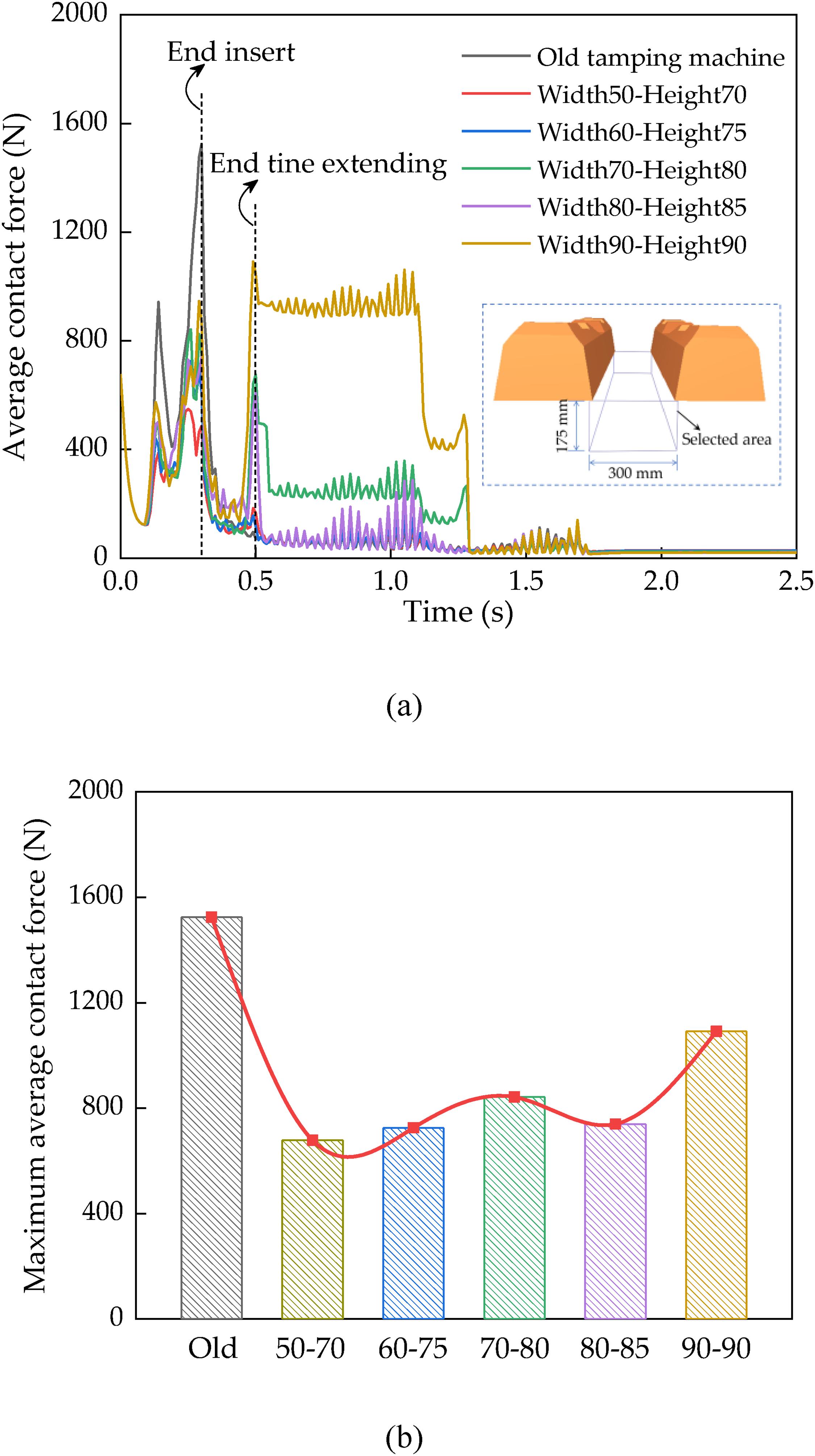
Upon completion of the insertion, the force on ballast is illustrated in Figure 10. The color scale indicates the magnitude of contact forces, while the arrows represent the direction of ballast movement. Figure 10(a) shows that numerous ballast particles around the tamping tine bear large contact forces, indicating that the impact force is transmitted to the ballast bed on a large scale when operating with the old tamping machine (Prasanna and Polojärvi, 2023). Figure 10(b) demonstrates that ballast particles experiencing large contact forces accumulate around the tamping tine during the operation of a new machine. However, the transmission scope of the external force from the new tamping machine is significantly smaller than that from old tamping machine. Hence, the new tamping machine can reduce impact-induced damage to the ballast.
Distribution of contact force acting on ballast upon completion of the insertion: (a) using an old tamping machine and (b) using a new tamping machine with a 50 mm width and 70 mm height.
The intense vibration of the crib ballast, induced by the insertion of a tamper, results in the loosening of the ballast in this section (Chi et al., 2024; Wang et al., 2023). Figure 11(a) presents the mean velocity of crib ballast. The average velocity exhibits similar trends for the old and new tamping machines. The average velocity surges during the insertion stage, peaking around its midpoint. Subsequently, the ballast in the crib vibrates slightly in the squeezing and rotating withdrawal stages. During the linear withdrawal stage, the velocity surges to a pronounced peak. Summarily, the ballast in the crib undergoes the most intense vibration at certain points in the insertion and linear withdrawal stages. This is highly unfavorable to the discrete aggregate in maintaining stable.
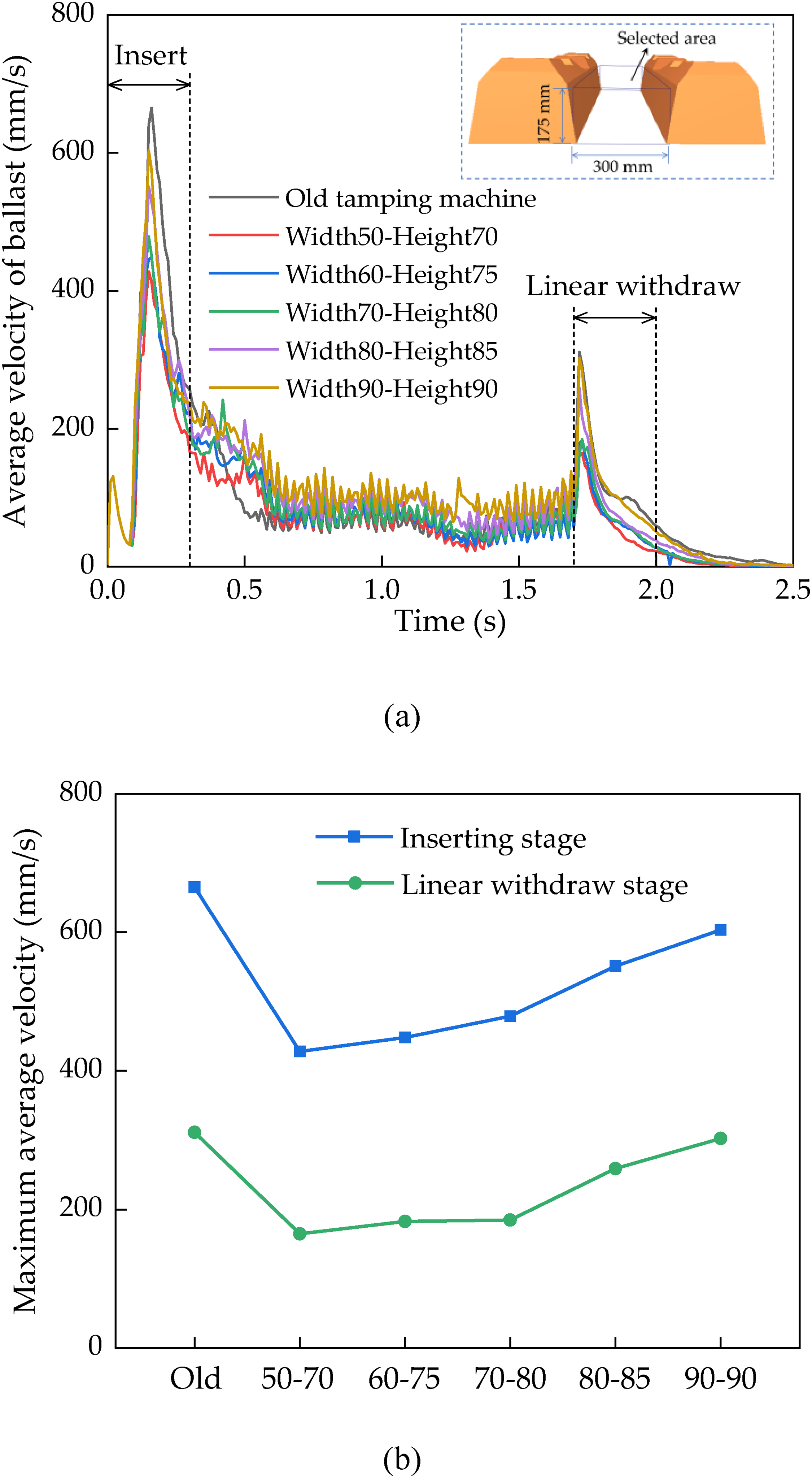
The average ballast velocity within the inter-sleeper zone: (a) temporal evolution of average velocity during tamping and (b) comparison of maximum values.
The peak average velocity in the insertion and linear withdrawal stages for different tamping machines is compared in Figure 11(b). During the insertion, the peak average values produced by the new tamping machines are markedly lower compared to those from the old machine, which is 665.35 mm/s. The maximum is the lowest for the new tamping machine with 50 mm width and 70 mm height, that is, 428.03 mm/s, decreasing by 35.67% compared to that for the old machine. In addition, the maximum average velocity increases with the tine size for the new machines. It is 603.49 mm/s for the new tamping machine with 90 mm width and 90 mm height, an increase of 40.99% compared to that for the new machine with 50 mm width and 70 mm height. The variation pattern of the maximum average velocity in the linear withdrawal stage is similar to that in the inserting stage. Therefore, the new tamping machines can significantly reduce the vibration of ballast in crib, especially for 50–70 mm width and 70–80 mm height.
Ballast in the crib rotates under the inserting effects of the tamping machine; this can also loosen the ballast in this section (Fu et al., 2021). The temporal evolution of average rotational velocity during tamping is depicted in Figure 12(a). The rotational velocity rises and then falls during the insertion stage, with significant variation rates observed. The rotational velocity peaks at the stage's midpoint. After the insertion stage, the rotational velocity exhibits minor fluctuations within a limited range until it enters the linear withdrawal stage. The average rotational velocity surges to a high value at the onset of the linear withdrawal stage. Finally, it decreases gradually until the ballast achieves stability. Hence, the crib ballast experiences the most unfavorable rotation at some points in the insertion and linear withdrawal stages.
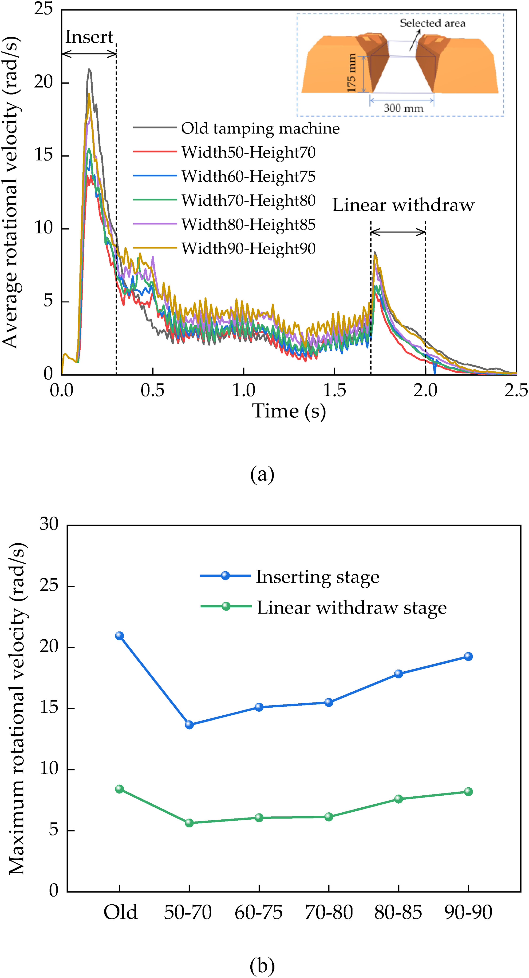
The average ballast rotational velocity within the inter-sleeper zone: (a) temporal evolution of average rotational velocity during tamping and (b) comparison of maximum values.
The maximum recorded rotational velocities are presented in Figure 12(b). The variation pattern of the peak average rotational velocity in the insertion stage is similar to that in the linear withdrawal stage. Nevertheless, the variation in the amplitude during insertion is relatively large. The maximum average rotational velocity during the inserting stage for the old tamping machine is the highest, that is, 20.95 rad/s. It is the lowest for the new tamping machine with 50 mm width and 70 mm height, that is, 13.66 rad/s, decreasing by 34.77% compared with that for the old tamping machine. Moreover, the maximum rotational velocity exhibits a positive correlation with the size of the new tamping machine. It is 19.26 rad/s for 90 mm width and 90 mm height, representing a 40.95% enhancement over the case of 50 mm width and 70 mm height. Therefore, the new tamping machines can mitigate ballast rotation, particularly for widths of 50–70 mm and heights of 70–80 mm.
The longitudinal displacement of crib ballast directly reveals the disruption to particles caused by tamping, as presented in Figure 13. One can observe from Figure 13(a) that the probability density of longitudinal displacement satisfies the normal distribution, and the longitudinal displacement of 0 mm is the axis of symmetry. This indicates that the movements of the ballast on the two sides of the tamping tine are similar. Figure 13(b) illustrates the mean longitudinal displacement of ballast on one side of the tamping machine. The mean longitudinal displacement using the old tamping machine, that is, 14.86 mm, is significantly larger than that using the new tamping machines. The mean longitudinal displacement is the minimum for the new tamping machine with 50 mm width and 70 mm height, that is, 9.04 mm, decreasing by 39.15% compared with that for the old tamping machine. Additionally, the mean displacement increases with the size of the new tamping machine. It is 10.55 mm for the new tamping machine with 90 mm width and 90 mm height, an increase of 16.69% compared with the new tamping machine with 50 mm width and 70 mm height. Therefore, the new tamping machines can mitigate the damage to ballast in the crib, especially for the new tamping machine with small sizes.
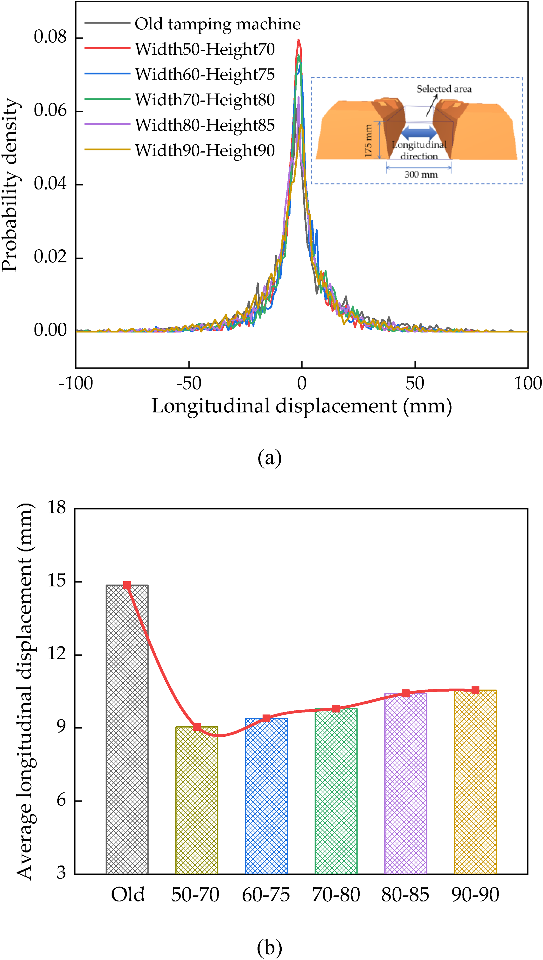
Longitudinal displacement of ballast in the area between sleepers: (a) probability density of longitudinal displacement and (b) average displacement.
The tamping operation serves to achieve ballast consolidation by eliminating the voids beneath the sleeper. Hence, the vertical displacement of ballast underneath the sleeper significantly governs the consolidation of ballast beneath the sleeper, as depicted in Figure 14. Figure 14(a) shows that the probability density is similar to a normal distribution. Most ballast particles beneath the sleeper move upward after tamping. The average vertical displacements obtained using different machines are compared in Figure 14(b). The average vertical displacement using the old machine is 16.32 mm. It is 15.74 mm using the new tamping machine with 50 mm width and 70 mm height, decreasing by 3.55% compared with that for the old tamping machine. The average vertical displacements for new tamping machines with 60–90 mm widths and 75–90 mm heights are all larger than those for the old tamping machine, ranging from 16.52–17.72 mm, increasing by 1.23%–8.57% compared with those for the old tamping machine. Therefore, the new large-sized tamping machine is beneficial for the ballast to fill the voids underneath the sleeper.
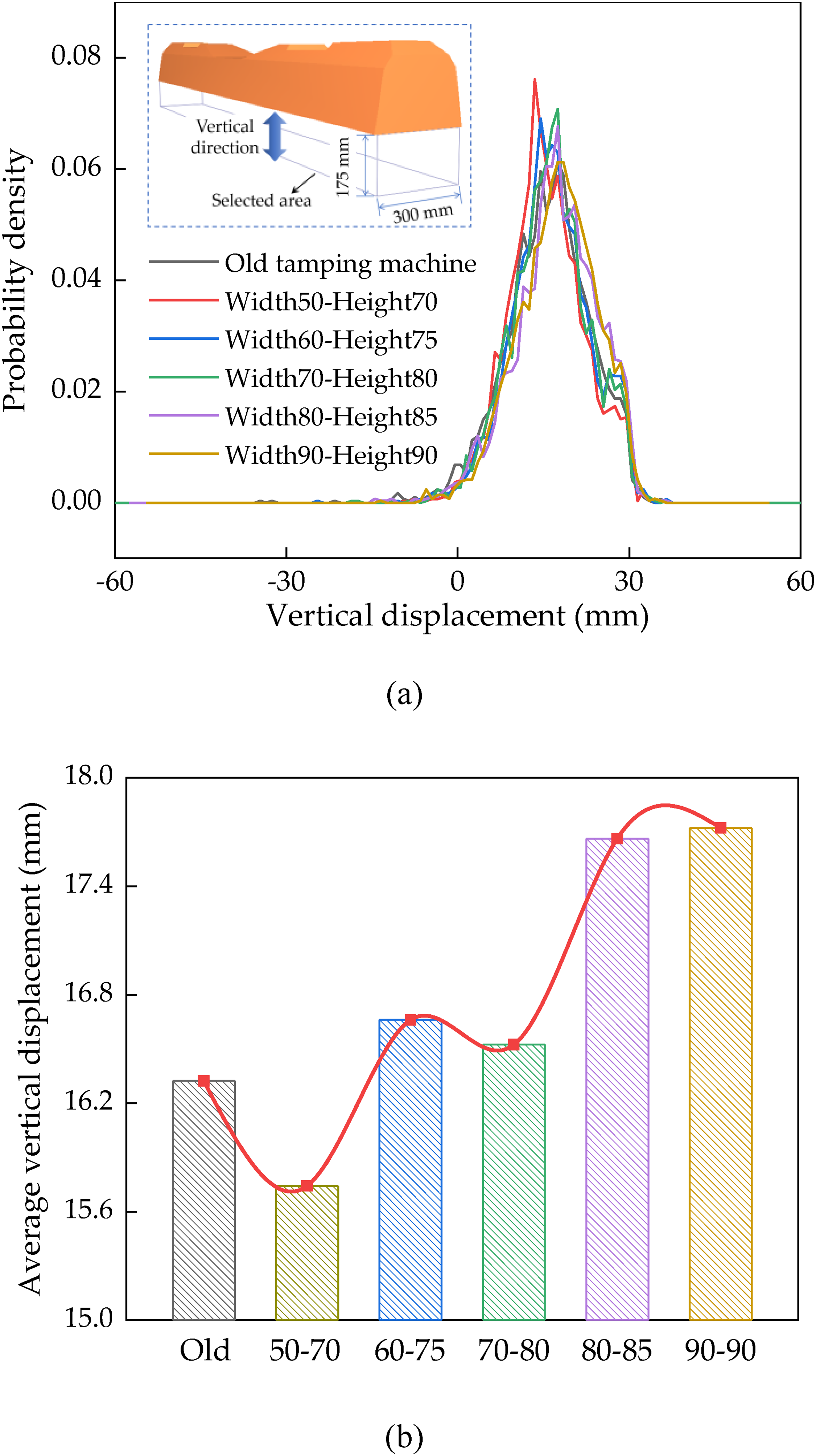
Vertical displacement of ballast underneath sleeper: (a) probability density of vertical displacement of ballast and (b) average vertical displacement of ballast.
In summary, the new tamping machines substantially mitigate the mechanical responses of ballast aggregates, particularly the contact forces acting on rock ballast. Consequently, contact force represents the most sensitive indicator of ballast damage. The new tamping machines with 50–70 mm width and 70–80 mm height perform the best for mitigating ballast degradation. Additionally, the new tamping machines with widths of 60–90 mm and heights of 75–90 mm can achieve sufficient ballast movement underneath the sleeper.
Mechanical states of the rock ballast bed
The new tamping machines are especially designed to improve the maintenance effects. Hence, the mechanical states of the rock ballast bed are analyzed to evaluate the maintenance effects achieved by the old and new tamping machines.
The coordination number of a particle quantifies the interparticle contacts it possesses (Ngo et al., 2025; Yuanjie Xiao et al., 2024). The mean coordination number during operation is presented in Figure 15(a). The number drops significantly during the insertion for all tamping machines. This implies that the insertion of the machine causes severe damage to the contact states. The average number gradually increases during the tine extending and squeezing stages. Interestingly, the number achieves a higher increase during tine retracting compared to that in the squeezing stage, indicating that tine retracting after squeezing is conducive to further improving interparticle contacts. In the final withdrawal stage, the number decreases slightly using the new tamping machine compared to that using the old tamping machine, implying that the new tamping machine induces less adverse impact on the interparticle contacts.
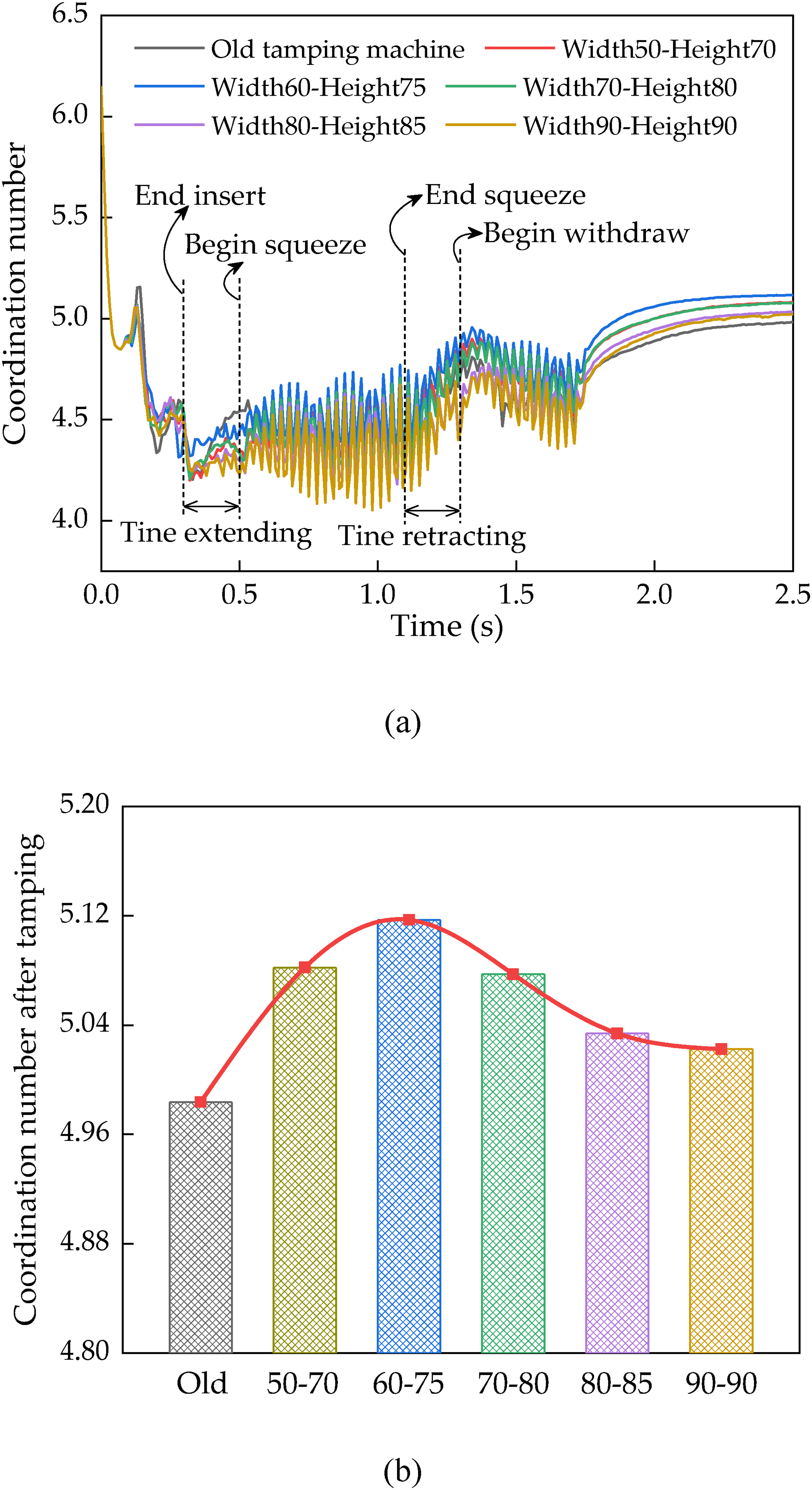
Mean coordination number of the ballast: (a) temporal evolution during tamping and (b) post-tamping number using different machines.
Figure 15(b) summarizes the post-tamping coordination number using different machines. The post-tamping number using the old tamping machine is the lowest at 4.984. The final average coordination numbers using the new tamping machines exceed that recorded for the old tamping machine. Specifically, the final average coordination number using the new tamping machine with 60 mm width and 75 mm height is the highest, that is, 5.117, an increase of 2.68% compared with that using the old tamping machine. Additionally, the final average coordination number using the new tamping machine then decreases with the size of the tamping tine. It is 5.022 using the new tamping machine with 90 mm width and 90 mm height, a decrease of 1.85% compared with that using the new tamping machine with 60 mm width and 75 mm height. Therefore, the new tamping machines offer a distinct advantage in enhancing the interparticle contact condition of ballast, particularly for tamping tine with small size.
The contact density represents the concentration of contact points across the ballast–sleeper interface. A higher contact density correlates with an enhanced stability at the ballast–sleeper interface (Fang et al., 2024; Mansouri et al., 2022). Figure 16(a) illustrates the time-history variation of the contact density. During the tine extending, the contact density initially decreases before increasing. This indicates that the preliminary extending of the tine can damage the contact state of the interface; however, the later tine extending gradually restores the contact state. The contact density rises during the squeezing, as the voids under the sleeper are progressively filled by the compaction of ballast particles. During tine retracting, the contact density exhibits slight fluctuations, indicating that the ballast underneath the sleeper maintains a stable state at this stage. In the final withdraw stage, the contact density decreases only slightly, indicating that the withdraw of the tamping machine minimally impacts the contact state.
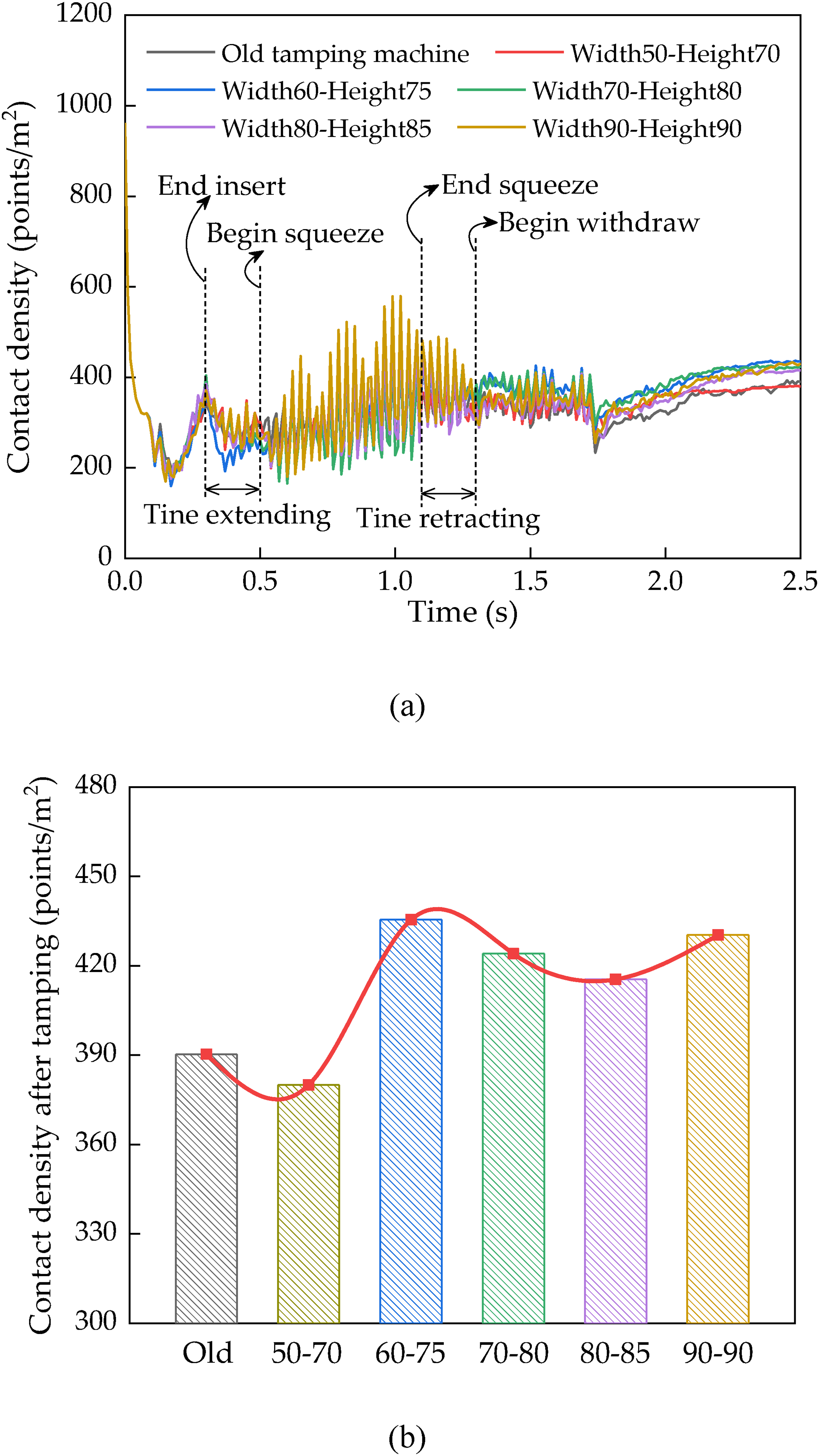
Average contact density across the ballast–sleeper interface: (a) temporal evolution of average contact density during tamping and (b) average contact density after tamping.
The post-tamping contact density is summarized in Figure 16(b). The post-tamping contact density obtained using the old machine is 390.29 points/m2. It is 380.01 points/m2 using the new machine with 50 mm width and 70 mm height, representing a 2.64% decrease compared to the old tamping machine. This indicates that this new tamping machine is less effective at maintaining the contact state. Additionally, the final contact densities are much higher for the new tamping machines with 60–90 mm width and 75–90 mm height compared with that for the old tamping machine. It is the highest for the new tamping machine with 60 mm width and 75 mm height, that is, 435.43 points/m2, increasing by 11.57% compared with that for the old tamping machine. Therefore, the new tamping machines with large sizes of the tamping tine can improve the interface contact state.
The contact configuration across the ballast–sleeper interface is shown in Figure 17. The point color denotes the contact force magnitude. One can see from Figure 17(a) that there are several noncontact areas on the underside of the sleeper after operating with the old machine, which are marked by orange circles. This is because the tamping tine is too small for the ballast within the circular region to be properly squeezed. The lack of interface contact can cause stress concentration under train loads, thus accelerating ballast degradation. One can notice from Figure 17(b) that there are still some noncontact areas on the underside of the sleeper after operating with the new machine with a 50 mm width and 70 mm height, marked by green circles; nevertheless, these areas are much smaller than those for the old tamping machine. One can observe from Figure 17(c) that the contact points are distributed uniformly on the underside of the sleeper after operating with a new machine with dimensions of 90 mm × 90 mm. This is greatly beneficial for the force diffusion under train loads.
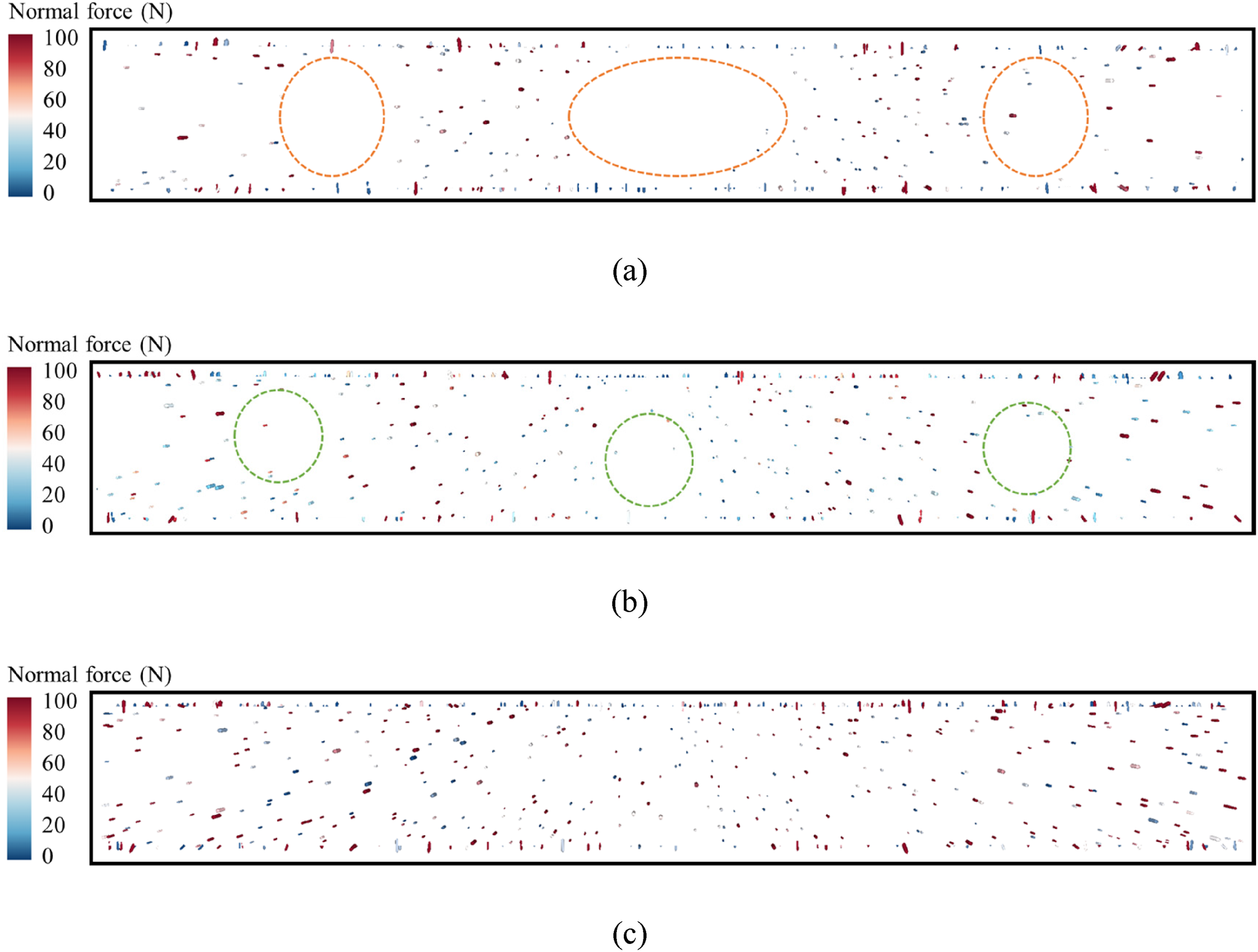
Distribution of contacts between ballast and underside of sleeper using different tamping machines: (a) old tamping machine, (b) new tamping machine with 50 mm width and 70 mm height, and (c) new tamping machine with 90 mm width and 90 mm height.
The evolution of ballast compactness beneath the sleeper during tamping is presented in Figure 18(a). The value is determined by measuring the volumetric proportion of the ballast constituent relative to the total demarcated region. (Xiao et al., 2024). The compactness increases during the insertion of the tamping machine. This is because the voids caused by sleeper lifting are filled by surrounding particles. During the tine extending, the compactness increases further, suggesting that the machine vibration drives the migration of ballast into the sub-sleeper voids. During the squeezing stage, the process of void-filling through particle rearrangement leads to a marked increase in ballast compactness. During the tine retracting, the compactness of the ballast exhibits slight fluctuations across all tamping machines. In the final withdrawal stage, the compactness remains stable for new machines, whereas it decreases significantly for the old tamping machine. This is because the retracted tamping tine can substantially mitigate the damage to the particle state during withdrawal.
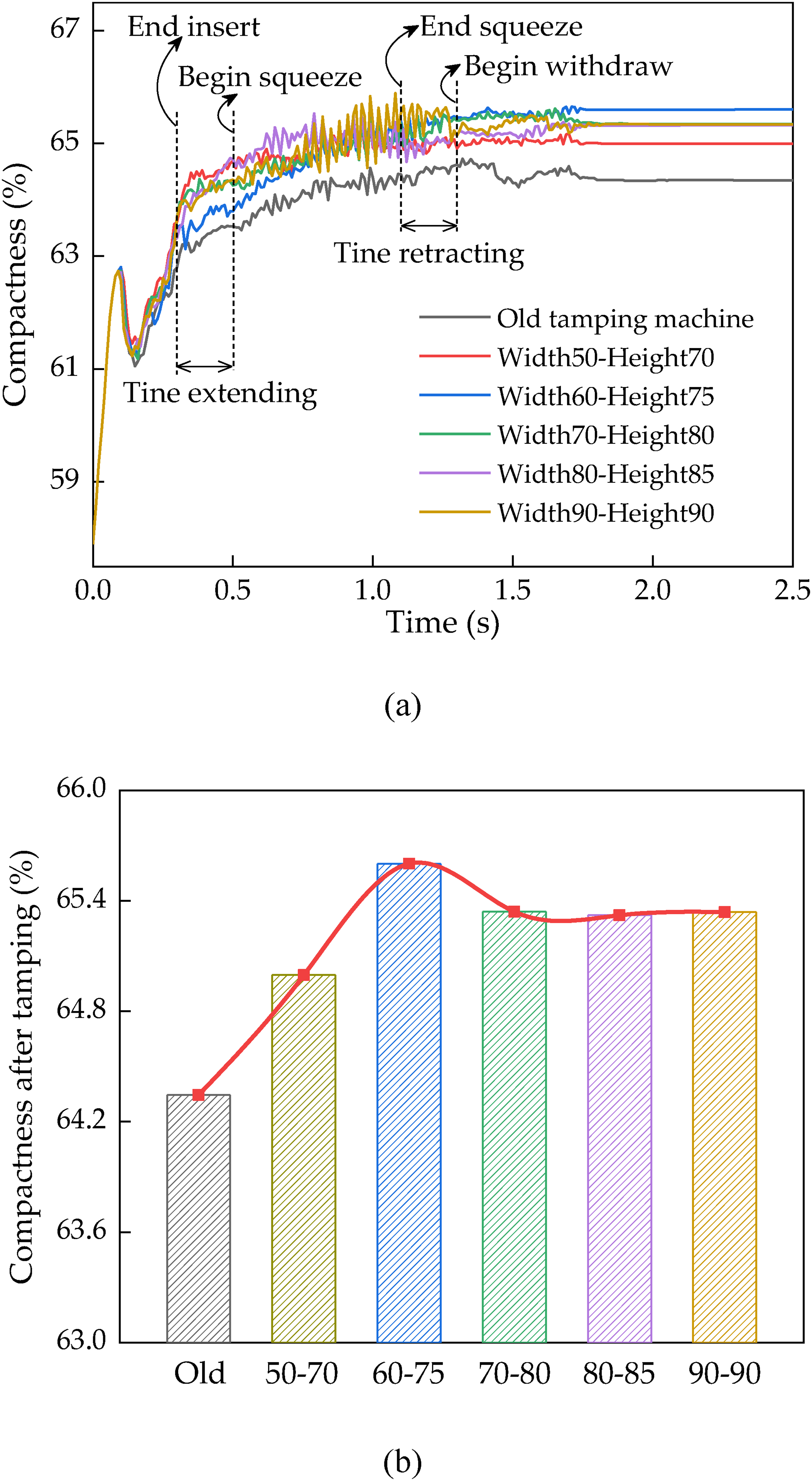
Compactness of ballast beneath sleeper: (a) temporal evolution during tamping operation and (b) post-tamping compactness.
The post-tamping compactness using different machines is compared in Figure 18(b). The post-tamping compactness using the old tamping machine was the lowest, that is, 64.35%. The post-tamping compactness using the new machine initially rises and then declines as the tamping tine size increases. It is the highest using the tamping machine with 60 mm width and 75 mm height, that is, 65.61%, with a performance margin of 1.95% over the old tamping machine. Additionally, the final compactness of ballast ranges from 65.32% to 65.34% for new tamping machines with 70–90 mm width and 80–90 mm height, demonstrating minimal difference between them, and the corresponding decreasing rates are 0.39%–0.43% compared with that using the new tamping machine with 60 mm width and 75 mm height. Therefore, the new tamping machines can significantly enhance the compactness and thus improve the carrying capacity of the ballast structure.
The uniformity of ballast compaction beneath the sleeper governs the force diffusion under train loads. Hence, the selected area beneath the sleeper is subdivided into 10 discrete sections, as illustrated in Figure 19, with the compactness in each part recorded during the tamping operation. The uniformity index can be calculated according to the differences in compactness across the parts, as expressed in Eq. (3). A higher uniformity index correlates positively with improved ballast compaction homogeneity.
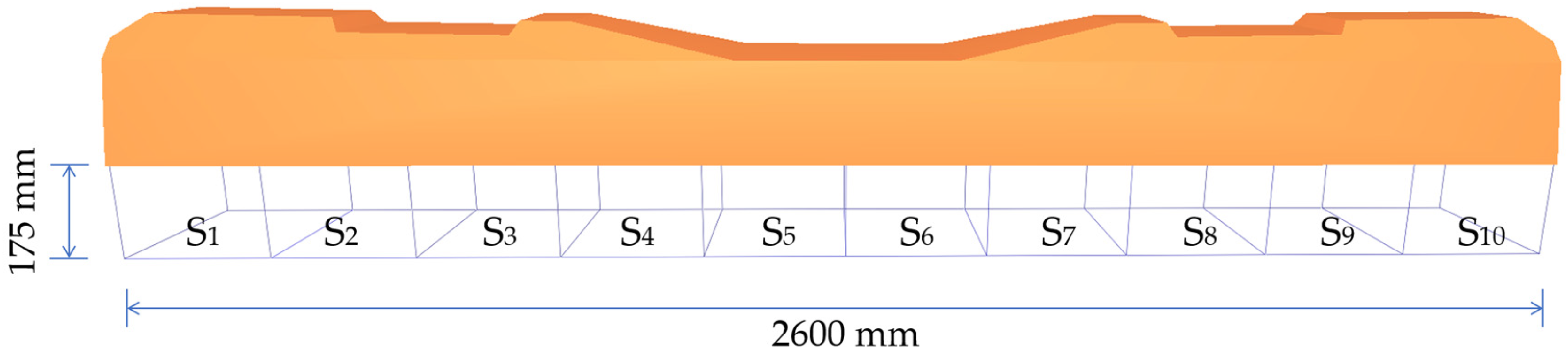
Section division for calculating the uniformity of ballast underneath the sleeper.
The uniformity evolution during tamping is demonstrated in Figure 20(a). It varies within a narrow range in the insertion stage and remains stable during tine extending. Notably, the uniformity index rises sharply during the squeezing, particularly for the new tamping machines. Hence, the squeezing contributes a lot to achieving a uniform distribution of ballast. In the final withdrawal stage, the uniformity index exhibits varying trends across different tamping machines. Specifically, the uniformity index of the ballast decreases for the new tamping machine with 60 mm width and 75 mm height, whereas it increases for the new tamping machine with 50 mm width and 70 mm height. Generally, the gap in the uniformity index of the ballast between the different tamping machines narrows during the final withdrawal stage.
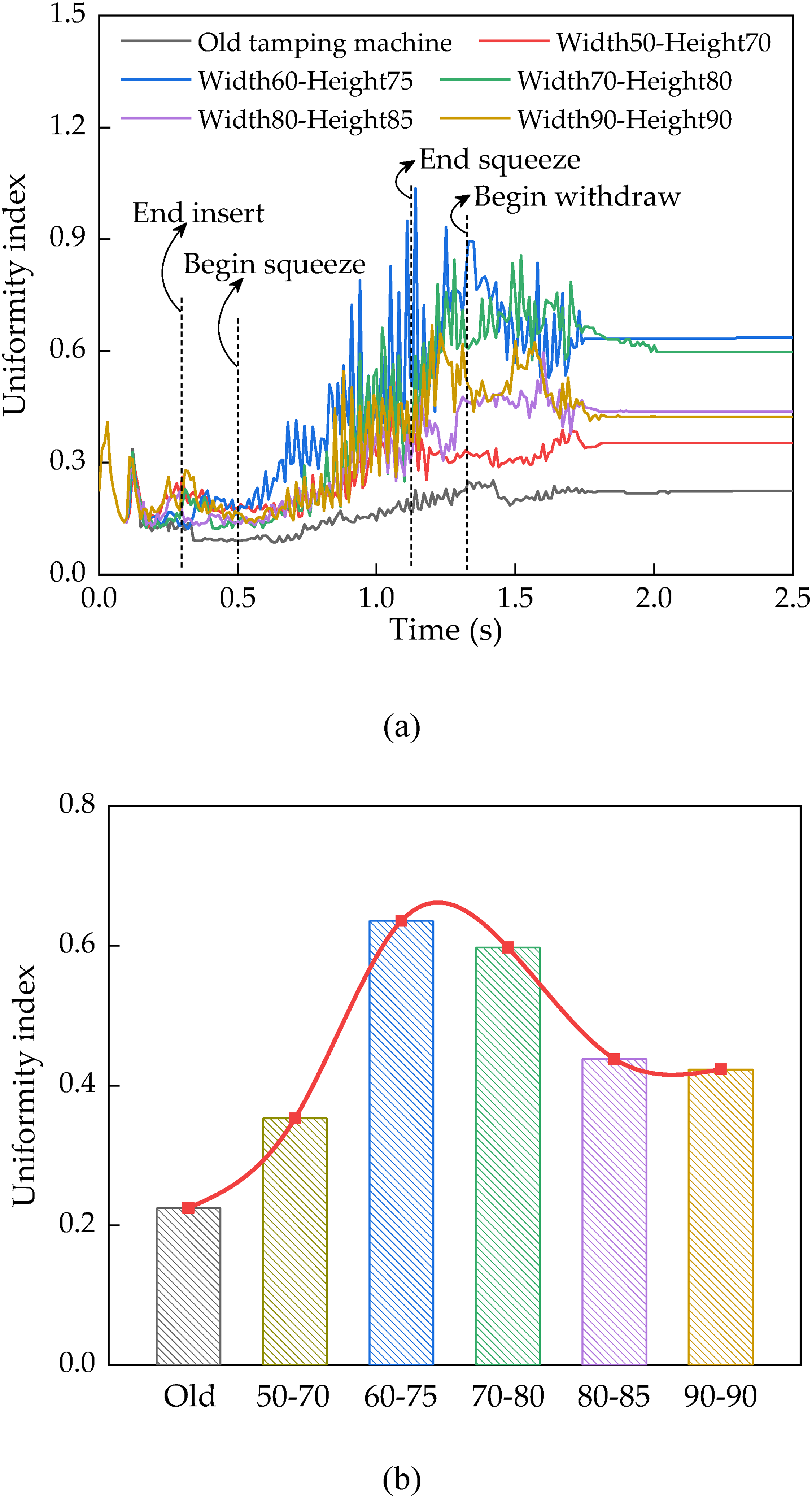
Uniformity of ballast underneath sleeper: (a) temporal evolution of uniformity index during tamping operation and (b) uniformity index after tamping operation.
The final uniformity indices of the ballast are presented in Figure 20(b). The final uniformity index for the old tamping machine is the lowest, at 0.225. For the uniformity index of the ballast after operating with the new tamping machines, it initially rises and then declines as the tamping tine size increases. The final uniformity index of ballast for the new tamping machine with 60 mm width and 75 mm height is the highest, that is, 0.636, increasing by 182.96% compared with that for the old tamping machine. It is 0.423 for the new tamping machine with 90 mm width and 90 mm height, a decrease of 33.45% compared to that for new machine with 60 mm width and 75 mm height. Therefore, the new tamping machines can significantly improve ballast uniformity, and the tine size plays a crucial role in determining it.
Summarily, the new tamping can significantly improve maintenance effects for rock ballast beds compared with the old tamping machine. Comprehensively, according to the coordination number, contact density, compactness, and uniformity of the rock ballast, the new tamping machines with widths of 60–70 mm and heights of 75–80 mm perform the best.
Conclusions
In this study, a new tamping method was developed, and the corresponding mechanical response of rock ballast particles and maintenance effects on the ballast bed were investigated. The major findings are summarized as follows:
A tamping method with an adjustable tamping tine was innovatively developed. It allows switching between retracted and extended states of the tine; that is, it is retracted in the insertion and withdrawal stages, while being extended in the squeezing stage. A model of ballasted track subjected to tamping was established. Additionally, the acceleration of the sub-sleeper ballast during tamping was quantified in field tests. The model was subsequently validated by benchmarking its simulations against these experimental measurements. The new tamping method can significantly reduce the mechanical response of rock ballast particles compared to the old method, especially for new tamping machines with small tamping tines. The maximum contact force acting on ballast during operation using a new tamping machine with a 50 mm width and 70 mm height decreases by 55.52% compared with that using the old tamping machine. Hence, the new tamping method can effectively mitigate rock ballast damage. Moreover, the new tamping machine with a sizeable tamping tine facilitates favorable ballast movement beneath the sleeper. The new tamping method can greatly improve the maintenance effects compared to the old tamping method. The uniformity index of the rock ballast beneath the sleeper using the new machine with 60 mm width and 75 mm height increases by 182.96% compared to that using the old tamping machine. Comprehensively considering the coordination number, contact density, compactness, and uniformity of the rock ballast, the new tamping machines with a width of 60–70 mm and height of 75–80 mm deliver optimal maintenance results for the ballast bed.
Finally, it should be noted that this study primarily focuses on conventional ballasted beds. Due to the increased structural complexity of the proposed tamping machine, its performance under extreme conditions, such as highly compacted ballast, where the machinery is more susceptible to damage, has not been accounted for. These factors constitute the primary limitations of the present research. Future research should focus on the production and the service performance of the new tamping machine under extreme conditions. Additionally, it should also be noted that the present study is positioned as a numerical investigation, focusing on evaluating the superior performance of the newly designed tamping device from a micro-mechanical perspective. These simulation results provide valuable insights into the conceptual feasibility of the method. In future research, a combination of field trials and laboratory tests will be conducted to further verify the effectiveness of the new tamping device from a macro-scale perspective under realistic operating conditions.
Footnotes
Author contributions
Yuze Wang: writing–original draft; data curation; validation. Shunwei Shi: project administration; supervision; formal analysis. Jiangwei Xue: investigation; visualization. Yue Liu: conceptualization; software. Liang Gao: methodology; resources.
Funding
This study was supported by the Fundamental Research Funds for the Central Universities (grant number 2024XKRC034), the National Natural Science Foundation of China (grant number 52408452).
Declaration of conflicting interests
The authors declared no potential conflicts of interest with respect to the research, authorship, and/or publication of this article.
Data availability statement
The data will be made available upon reasonable request.
Highlights
A novel tamping method with automatic telescoping tine was developed. Mechanical responses of rock ballast were analyzed to mitigate damage. Mechanical states of rock ballast were analyzed to enhance maintenance effects. The optimal tine size for the novel tamping method was determined.