
Abstract
Short fatigue crack growth is strongly affected by microstructural heterogeneity, crack-size effects, and loading-path dependence, leading to nonlinear, intermittent, and locally sensitive propagation behavior. Conventional long-crack growth models based on linear elastic fracture mechanics are therefore insufficient for describing short-crack propagation under different loading conditions. To address this issue, this study proposes a multi-scale short fatigue crack growth rate model that couples crack-tip strain energy density, crack-size effect, microstructural barrier resistance, and crack closure correction. Compared with the existing short-crack models, the proposed model introduces a microstructural barrier penetration function and a crack-opening correction factor to describe crack arrest, re-initiation, growth-rate fluctuation, and the effective crack-driving force. The model is validated using literature-reported experimental datasets for LZ50 steel, EA4T steel, CuNi2Si alloy, and 42CrMo steel under different load sequences, loading frequencies, loading paths, loading modes, and load levels. The results show that the proposed model can reasonably capture the nonlinear evolution of short-crack growth rates under multi-condition loading. Quantitative evaluation shows an average log-scale coefficient of determination of 0.894, with 96.1% of the evaluated data points falling within the factor-of-three error band. These results indicate that the proposed model provides a physically interpretable framework for short fatigue crack growth assessment. Further validation under random or spectrum loading is still required.
Keywords
Introduction
The propagation behavior of short fatigue cracks (SFCs) is one of the key factors determining the fatigue life of materials and structures, particularly in critical engineering fields such as aerospace, automotive manufacturing, and energy equipment. Structural failures induced by SFCs are frequently reported in these industries, posing significant challenges to engineering applications (Li et al., 2025; Su et al., 2025; Wang et al., 2025). Compared with long cracks, the propagation of SFCs is more strongly influenced by the combined effects of microstructural features, varying loading conditions, and scale effects, exhibiting pronounced nonlinearity and stochasticity. However, conventional crack growth models based on linear elastic fracture mechanics (LEFM) are inadequate for accurately describing the propagation mechanisms and growth rates of short cracks, leading to considerable limitations in prediction accuracy and applicability (Leonetti et al., 2021). As shown in Figure 1, significant differences exist between short cracks and long cracks in terms of both propagation rate and propagation characteristics. The growth curve of SFCs exhibits pronounced nonlinear fluctuations and frequent crack arrest phenomena, highlighting the substantial influence of microstructural features and scale effects. In contrast, long cracks generally propagate in a relatively stable and linear manner, which can be well described using conventional LEFM-based approaches (Dekker et al., 2021; Gao et al., 2023). These distinct characteristics make the prediction and control of short-crack propagation considerably more complex and challenging. In practical engineering applications, the loading conditions experienced by structural components are usually diverse and complex. Crack growth models developed under simple or single loading conditions are often insufficient to realistically reflect the fatigue crack behavior of structures operating in complex service environments. Moreover, the propagation process of SFCs involves multi-scale interactions and coupling effects across the micro-, meso-, and macro-scales. Traditional single-scale models often neglect the interaction mechanisms among different scales, making it difficult to fully reveal the intrinsic laws governing crack growth behavior (Li et al., 2024; Long et al., 2023; Sun et al., 2023). Therefore, investigating the propagation mechanisms and developing multi-scale crack growth rate models for SFCs under various loading conditions is of great theoretical significance and practical engineering value. Such research efforts are essential for accurately describing the propagation behavior of short cracks under complex loading scenarios, improving the fatigue reliability of engineering structures and reducing service risks (Gaole et al., 2023; Lei et al., 2025; Shuancheng et al., 2023).
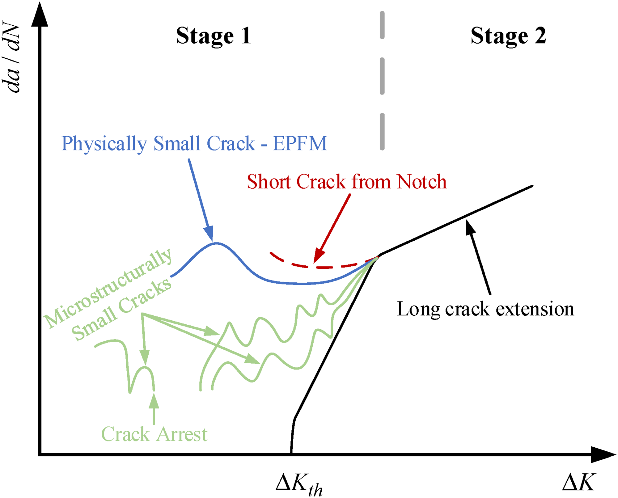
Schematic illustration of short and long fatigue crack growth rates.
In recent decades, substantial efforts have been devoted to experimental observations, mechanism analysis, and model development of SFC growth. These studies have confirmed that short-crack propagation is strongly affected by crack size, microstructural barriers, loading path variation, and local stress–strain conditions, resulting in nonlinear, discontinuous, and multi-scale growth behavior. Early works by Suresh (1998), Newman and colleagues (Newman et al., 1999, 2000; Wu et al., 1998), and Tanaka and colleagues (Tanaka and Mura, 1981) systematically revealed, through fatigue testing and microstructural observations, the characteristic phenomena of “crack arrest and re-initiation,” grain boundary (GB) blocking effects, and discontinuous crack paths during short-crack propagation, laying a solid foundation for understanding the underlying mechanisms of short-crack growth. Subsequently, ASTM E647 (American Society for Testing and Materials, 2015) provided a unified definition and classification framework for short cracks, categorizing them into four typical types: microstructurally small cracks (MSCs), physically small cracks (PSCs), mechanically small cracks (MenSCs), and environmentally small cracks (ESCs). In terms of modeling approaches, researchers such as Elber (Wolf, 1970) and McEvily (Mcevily et al., 2003) modified the traditional Paris law (Paris and Erdogan, 1963) (equation (1)) and LEFM theory (Irwin, 1957) by introducing effective stress intensity factors and intrinsic crack length parameters, thereby developing a series of short-crack growth rate models considering crack-size effects (Bang and Ince, 2020; Chan and Lankford, 1988; Vallellano et al., 2009). El Haddad et al. (1979) proposed a classic method for short-crack modeling by introducing the intrinsic crack length

With the increasing demands of engineering applications, growing attention has been paid to the propagation behavior of short cracks under complex loading conditions (Liao et al., 2020; Yang et al., 2018, 2020; Zhao et al., 2006). In recent years, multi-scale modeling approaches have gradually emerged internationally, aiming to establish a connection between microstructural mechanisms and macroscopic crack growth behavior. Recent studies have further emphasized microstructure-sensitive short-crack growth modeling, three-dimensional crack initiation and propagation analysis, and data-driven fatigue life prediction, providing new perspectives for short-crack growth assessment (Lei et al., 2025; Li et al., 2024, 2025; Long et al., 2023; Su et al., 2025; Sun et al., 2023). Methods such as crystal plasticity finite-element modeling, continuum damage mechanics, and cohesive zone models have been employed to couple different scales in the analysis of fatigue crack growth. Meanwhile, advanced experimental techniques, including digital image correlation, in-situ scanning electron microscopy (SEM), and X-ray computed tomography, have further revealed the propagation characteristics of short cracks under variable amplitude loading, multi-axial loading, and other complex loading conditions (Qin et al., 2023; Tao et al., 2023; Zhang et al., 2019). However, considerable challenges remain in the coupling mechanisms between scales, transient crack propagation behavior, and loading path sensitivity. A comprehensive and generalizable modeling framework for short-crack growth is yet to be fully established. It has been demonstrated that various factors, such as load sequence, loading frequency, loading path, and non-proportional multi-axial loading, significantly affect the propagation rate and growth mechanisms of short cracks (Liao et al., 2020; Qin et al., 2020; Wang et al., 2024; Yang et al., 2017). For instance, changes in load sequence may cause abrupt variations or acceleration in crack growth rates; differences in loading frequency influence the microstructural response and crack propagation behavior; and alterations in the loading path can directly modify the crack growth direction and propagation mechanisms. Nevertheless, most existing short-crack growth models are developed under single loading conditions, making it difficult to accurately describe the propagation mechanisms and rate characteristics of short cracks subjected to complex service environments. To capture the complex initiation and propagation behavior of SFCs, various experimental techniques have been employed by researchers, including direct observation, potential drop methods, acoustic emission monitoring, replica techniques, and groove line methods (Xie et al., 2017; Yang et al., 2018). In particular, the combined application of replica techniques and high-resolution microscopy has become a widely used and effective method for investigating short-crack propagation behavior (Foletti et al., 2018; Sun et al., 2019). Although significant progress has been made in characterizing short-crack growth behavior and experimental observation techniques, there is still a lack of comprehensive studies on the propagation mechanisms and rate modeling of short cracks under complex loading conditions. A unified and robust prediction methodology applicable to complicated service environments remains to be further developed.
Therefore, to address the limitations of the existing short-crack growth models under different loading conditions, this study develops a multi-scale SFC growth rate model by coupling crack-tip strain energy density, crack-size effect, microstructural barrier resistance, and crack closure correction. The main contribution of this work is not a simple empirical combination of the existing terms, but the construction of a physically interpretable framework in which the effective crack-driving force, short-crack size dependence, microstructural resistance, and crack-opening behavior are jointly considered. Compared with the models proposed by Zhao et al. (2006) and Yang and Zhao (2012), the present model provides two main improvements. First, a microstructural barrier penetration function is introduced to describe the progressive interaction between the crack tip and microstructural obstacles, thereby improving the description of crack arrest, re-initiation, and growth-rate fluctuation. Second, a crack-opening correction factor is incorporated to modify the effective crack-driving force under cyclic loading. These extensions enable the model to better describe the nonlinear and stage-dependent propagation behavior of SFCs under different prescribed loading conditions. The proposed model is evaluated using literature-reported experimental datasets for LZ50 steel, EA4T steel, CuNi2Si alloy, and 42CrMo steel, covering different load sequences, loading frequencies, loading paths, loading modes, and load levels. Quantitative statistical indicators are further introduced to assess the model’s performance. Through this work, a physically interpretable modeling framework is provided for SFC growth assessment under multi-condition loading.
The remainder of this paper is organized as follows. The second section introduces the initiation mechanisms and growth characteristics of SFCs. The third section presents the development of the proposed short-crack growth rate model, including its physical basis, parameter interpretation, and fatigue life prediction procedure. The fourth section validates the proposed model using literature-reported experimental datasets under different loading conditions and provides a quantitative statistical evaluation. Finally, the last section summarizes the main conclusions and discusses the limitations and future work.
Initiation mechanism and growth characteristics of SFCs
Fatigue short cracks refer to fatigue cracks that have not yet fully entered the applicable range of LEFM and are characterized by relatively small crack sizes. The initiation and propagation behavior of short cracks plays a decisive role in determining the fatigue life of materials. In this stage, crack growth behavior is not only significantly affected by the local stress–strain state but is also closely related to microstructural features, such as grain structure, dislocation motion, and the distribution of second-phase particles. Pearson (1975) was the first to observe the distinct differences in propagation behavior between short and long cracks. He found that short cracks typically propagate at higher rates than long cracks under the same stress intensity factor range, and highlighted the strong nonlinearity and local sensitivity associated with short-crack growth. The propagation of short cracks during this stage exhibits pronounced stochasticity and heterogeneity, often accompanied by the phenomenon of “crack arrest and re-initiation.” Specifically, short cracks may temporarily stop growing when encountering microstructural obstacles, such as GBs or twin boundaries, but can re-initiate growth under continued cyclic loading (Kamaya, 2004; Tao et al., 2023). The propagation path of short cracks is usually governed by the combined effects of crystallographic orientation, GB strength, and local stress gradients. Consequently, the growth behavior of short cracks is often characterized by discontinuous, intermittent propagation with sudden changes in growth rate, which is significantly different from the stable and continuous growth behavior typically observed in the long crack stage.
The initiation of SFCs typically occurs at microdefect regions located on or near the material surface, such as machining scratches, inclusions, and second-phase particle interfaces (Nalla et al., 2002; Newman et al., 2000). Under cyclic loading, these regions generate localized stress concentrations, leading to plastic deformation and strain accumulation, and eventually result in the nucleation of microcracks. At the microscale, these initial cracks may be initially passivated by microstructural obstacles such as GBs. However, they can subsequently be reactivated within stress concentration zones and propagate across grains, gradually evolving into larger PSCs. As shown in Figure 2, the propagation paths of SFCs at the grain scale are governed by various micromechanisms. Cracks may initiate at pores or microstructural defects and propagate along specific crystallographic orientations. Upon encountering GBs, cracks may experience path deflection or temporary arrest. Some cracks may even terminate prematurely due to unfavorable orientations or insufficient stress distribution, resulting in the formation of ineffective short fatigue cracks (ISFCs). In contrast, dominant effective short fatigue cracks (DESFCs) can continue to propagate under cyclic loading and may coalesce with other cracks at GB intersections, further accelerating the damage evolution process (Zhao et al., 1999). In addition, the coupling effects between local stress fluctuations and grain structure are important contributors to the highly heterogeneous propagation behavior of SFCs. The existence of these complex micromechanisms indicates that the propagation behavior of SFCs cannot be accurately described using a single parameter, such as the stress intensity factor alone. Therefore, it is essential to incorporate multi-scale information into modeling and prediction frameworks to capture the intricate propagation characteristics of SFCs. It should be noted that the DESFC and ISFC concepts are used here as a mechanistic interpretation framework based on reported microscopic observations, rather than as direct experimental evidence newly obtained in this study.
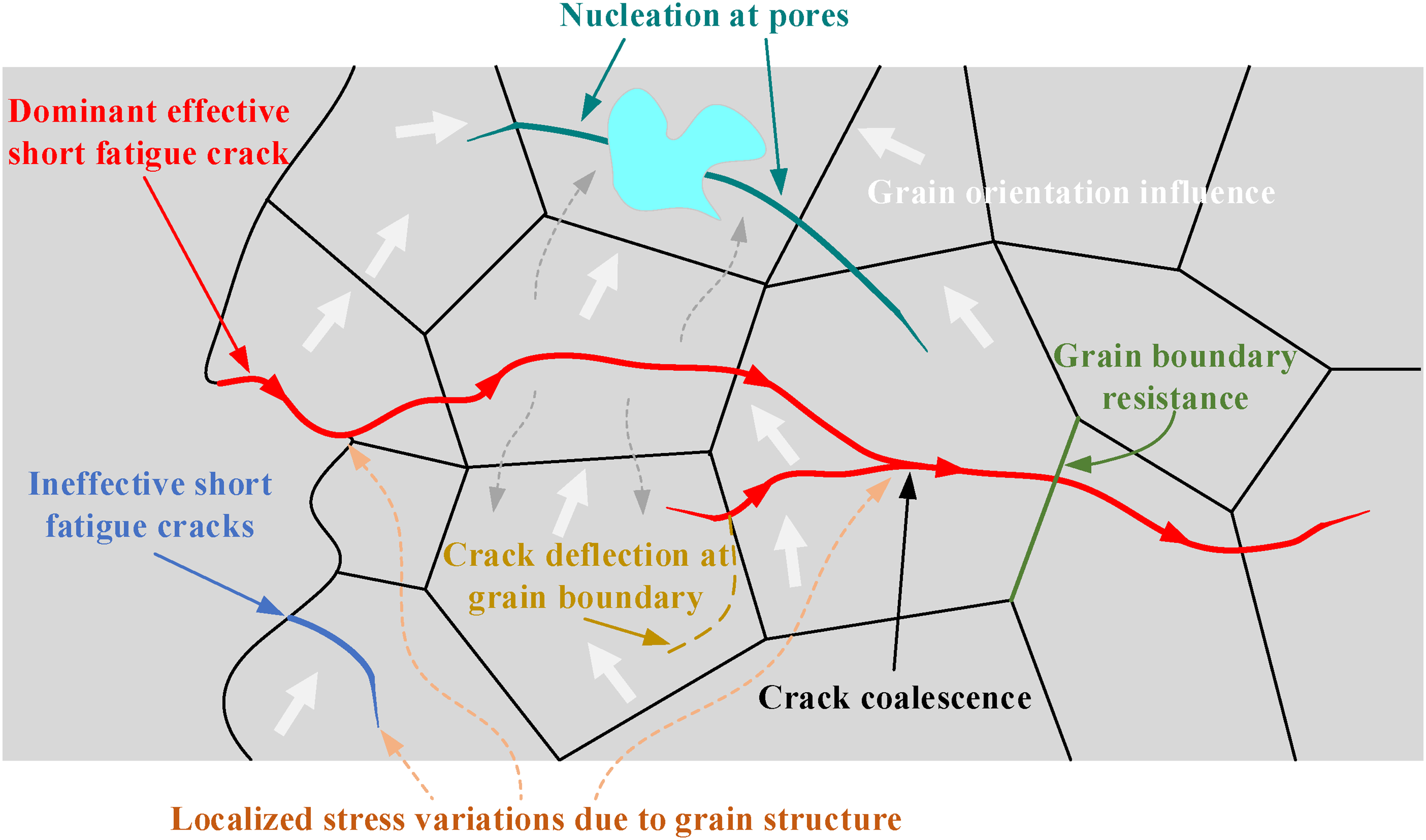
Schematic illustration of short fatigue crack propagation and microstructural interactions.
In addition, when SFCs propagate across GBs, their propagation paths and growth rates are not only affected by the location of the GBs but are also closely related to the orientation of slip planes, the misorientation angles between adjacent grains, and the geometric relationships of the GB interfaces. The propagation path of SFCs within the microstructure is often governed by the combined effects of grain orientation, slip plane direction, and GB characteristics. When an SFC propagates from one grain to a neighboring grain, it is frequently hindered by the GB, resulting in crack arrest, deflection, or branching, which in turn affects the crack growth rate and propagation mode. Figure 3 schematically illustrates the influence of the GB plane and the slip planes of adjacent grains on the propagation behavior of SFCs during the process of crossing GBs. In this figure, the misorientation angles (
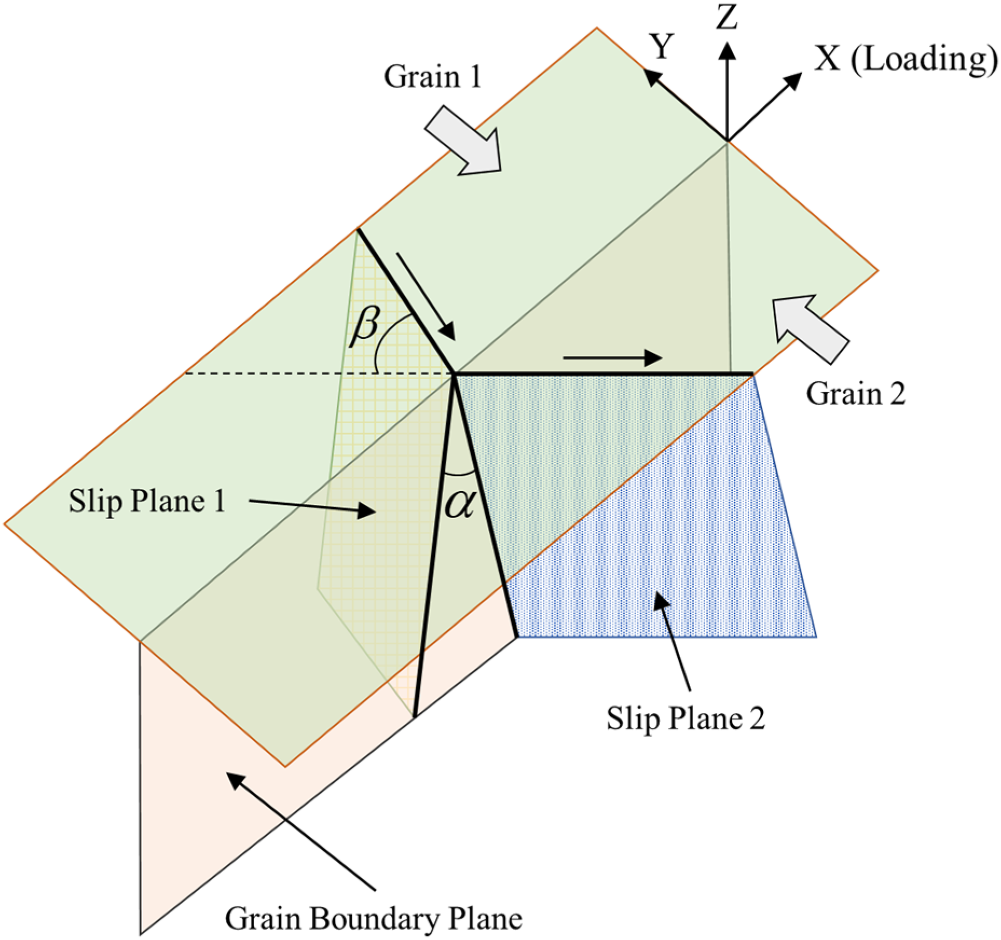
Geometrical relationship between slip planes in adjacent grains and grain boundary plane during short fatigue crack propagation (Panwar et al., 2018).
To further investigate the influence of GBs on the propagation path and behavior of small cracks during the crack growth process, an in-situ fatigue crack growth experiment conducted by Tao et al. (2023) on CP-Ti was referenced. Figure 4 presents the in-situ observation results of the crack propagation behavior in CP-Ti. As shown in Figure 4(a1), the main crack initiated from an artificial defect and propagated along the GB within Grain 7. However, the propagation of the main crack was significantly hindered by the GB, making it difficult for the crack to penetrate the boundary. Subsequently, after multiple loading cycles, a secondary crack was initiated near the tip of the main crack, as illustrated in Figure 4(a2). With the increasing number of load cycles, the secondary crack gradually extended and approached the main crack, as shown in Figure 4(a3) to (a5). Eventually, the secondary crack connected with the main crack, leading to stress relaxation at the original crack tip and a pronounced deflection of the crack path, is shown in Figure 4(a6). This phenomenon indicates that the interaction between the main crack and the secondary crack not only alters the crack propagation path but also effectively reduces the crack driving force.
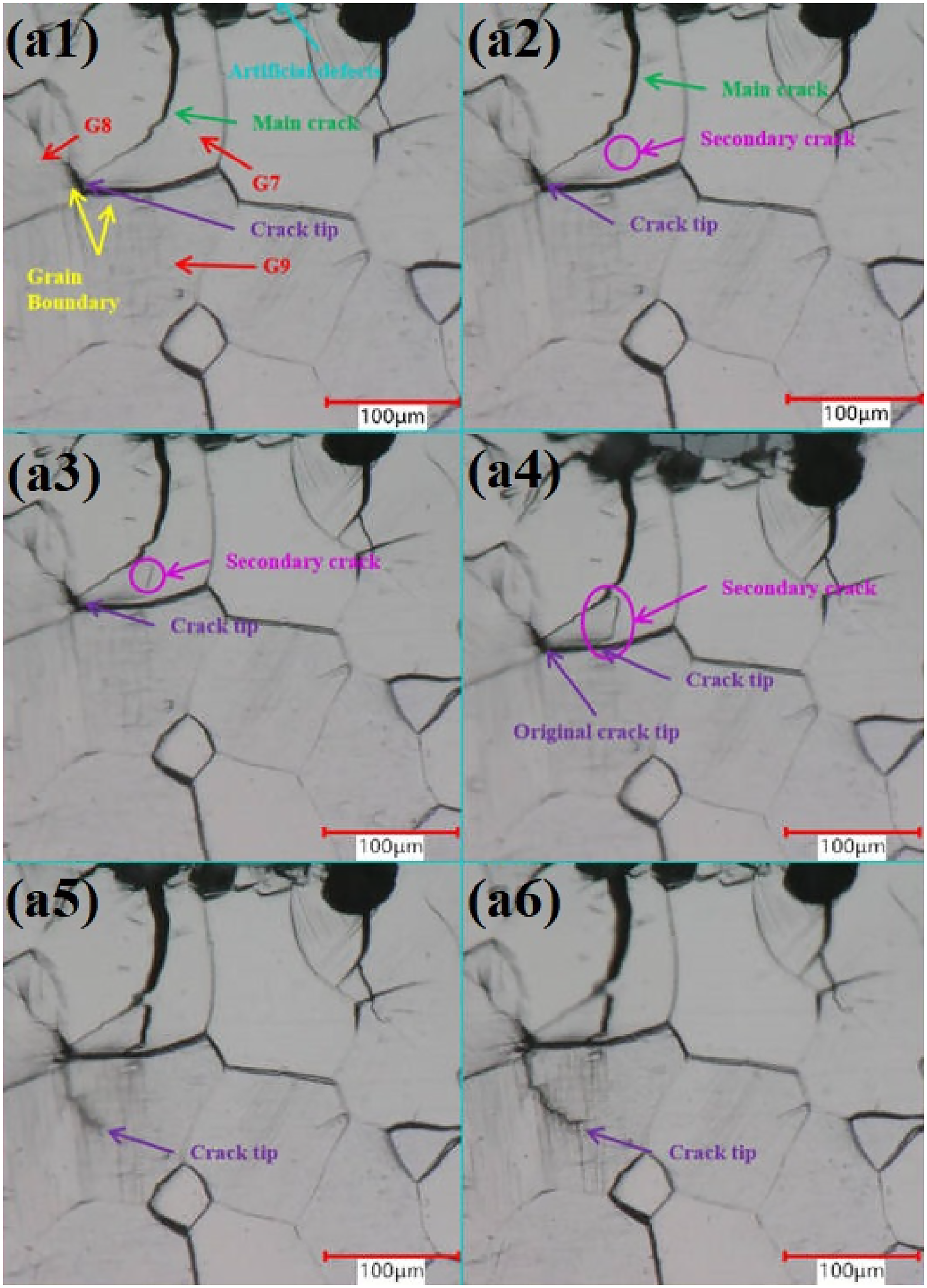
In-situ microscopy images of small fatigue crack propagation behavior in CP-Ti: (a1) Main crack initiation and propagation near grain boundaries, (a2) secondary crack initiation near the main crack tip, (a3) gradual growth of the secondary crack, (a4) connection of secondary crack with the main crack, (a5) crack tip shielding after crack coalescence, and (a6) crack path deflection and continuous propagation (Tao et al., 2023).
Currently, the most widely adopted classification method for SFCs is based on the ASTM E647 standard (American Society for Testing and Materials, 2015), which categorizes SFCs into four types: MSCs, PSCs, MenSCs, and ESCs. Here, the abbreviation MenSCs is used to denote mechanically small cracks and to distinguish this category from MSCs and PSCs within the ASTM E647 classification framework. This classification not only considers the crack size itself but also reflects the different microstructural environments and dominant mechanisms associated with each type of crack. Such definitions provide a deeper understanding of short-crack propagation behavior and highlight its significance in fatigue life prediction.
As a simple and practical tool for fatigue assessment, the classic K–T diagram has been widely used to describe the variation trend of the fatigue limit with respect to defect or crack size. As shown in Figure 5, the K–T diagram employs the crack/defect size a as the horizontal axis and the stress amplitude In region 1 ( In region 2 ( In region 3 (
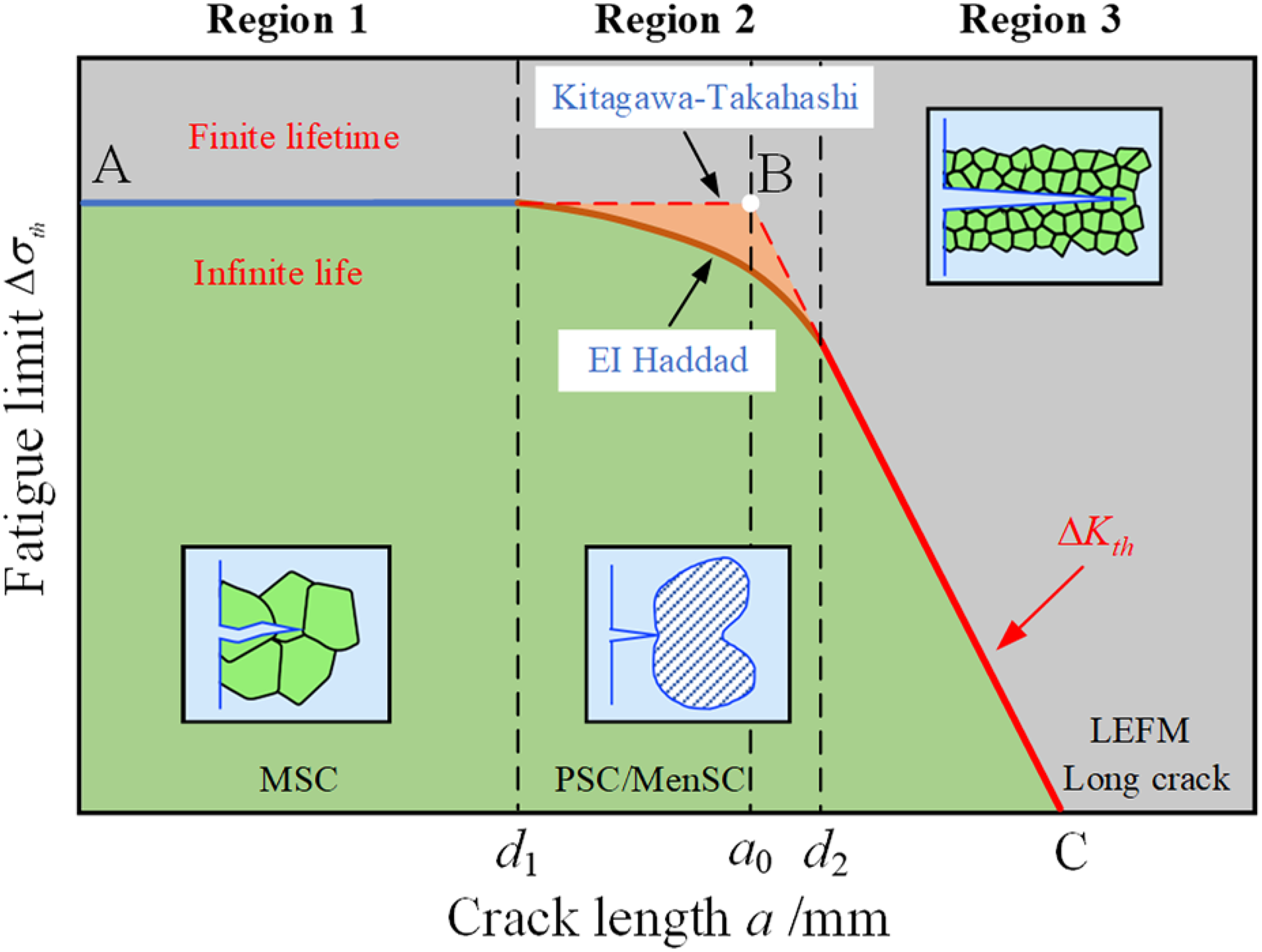
Kitagawa–Takahashi diagram and El Haddad modification illustrating the fatigue limit transition from defect-free to long-crack behavior (Gaole et al., 2023; Zerbst et al., 2021).
In Figure 5, the horizontal line AB represents the fatigue limit
However, the original K–T model (Kitagawa and Takahashi, 1976) presents a “discontinuity” issue near

Short-crack growth rate modeling
The evolution of fatigue damage in materials and structures during service is typically a multi-scale process. At the macroscopic level, it is characterized by the gradual degradation of mechanical properties and eventual failure, while at the microscopic level, it primarily involves the initiation and propagation of microcracks and their interaction with microstructural features. In particular, under complex loading environments, the propagation behavior of SFCs within materials is influenced by the coupling of multiple factors, exhibiting pronounced characteristics of nonlinearity, discontinuity, and multi-scale evolution. Traditional fatigue crack growth rate models are mostly based on LEFM theory, which are mainly applicable to the stable growth stage of long cracks. However, these models are insufficient to accurately describe the initiation and early propagation behavior of SFCs. Therefore, an in-depth investigation of the propagation mechanisms of SFCs and the development of reliable short-crack growth rate models are essential for improving fatigue life prediction of engineering structures.
Existing representative models for short-crack growth
In view of the complexity and particularity of SFC propagation behavior, a variety of representative short-crack growth rate prediction models have been proposed based on extensive fatigue experiments and mechanism investigations. Most of the existing models are developed by improving and extending traditional fatigue crack growth theories, such as the linear fatigue cumulative damage theory (Miner's rule) (Miner, 1945), the Paris law (Paris and Erdogan, 1963), the Coffin–Manson equation (Coffin, 1954; Manson, 1953), and LEFM theory (Irwin, 1957). These models have been specifically modified to address the key issues associated with SFC propagation, including the crack-size effect, microstructural influence, crack closure effect, and loading characteristics. The primary objective of these improvements is to more accurately describe the nonlinear and unstable characteristics exhibited by SFCs during the initiation and early propagation stages.
Hobson (1982) was the first to propose a crack growth rate prediction equation specifically addressing the characteristics of short-crack propagation within individual grains. This model assumes that the propagation behavior of SFCs is jointly governed by the crack length and its distance from the nearest GB. The model suggests that the crack growth rate gradually increases with the growth of the crack length during propagation. The mathematical expression of the model can be described as follows


In addition, to overcome the limitations of traditional stress intensity factor-based models in predicting SFC propagation, some researchers have attempted to modify the

On this basis, considering the effect of the stress ratio R on the threshold for crack propagation, a crack growth threshold model related to the stress ratio was further proposed. The mathematical expression of the model is given as

To address this issue, Newman et al. (2000) and Zhao et al. (1989) proposed the concept of the effective stress intensity factor range (

In addition, to better characterize the driving force of the plastic zone at the crack tip, Shyam et al. (2005) proposed a dislocation-based crack growth model. The mathematical expression of the model is given as

Although the Shyam model exhibits relatively high accuracy in predicting the propagation behavior of PSCs, it fails to fully account for the fluctuation characteristics of crack growth rates induced by microstructural features during the propagation of MSCs. Consequently, the model has limitations in reasonably explaining the instability and heterogeneity observed in the crack growth process. Moreover, the crack growth rate in this model is assumed to have a linear correlation with the product of the crack tip opening displacement and its cyclic variation, which may restrict its applicability and generalization to complex loading conditions or materials with significant microstructural crack characteristics. In addition, to address the applicability limitations of the traditional stress intensity factor K in predicting crack growth behavior, Polák and Zezulka (2005) proposed the use of the elastic–plastic fracture mechanics parameter J-integral to characterize the crack tip driving force. Their studies indicated that the correlation between the crack growth rate and J-integral is superior to that of the traditional K-based model, providing a stronger relationship for crack growth prediction. Therefore, based on the Paris law for crack growth rate, Polák and Zezulka (2005) further introduced the

To further improve the accuracy of the model, Döring et al. (2006) proposed a crack growth rate model considering the effective

The strain energy density is considered one of the effective parameters for characterizing the energy features in the crack tip region and is commonly used to evaluate the stored deformation energy in the material elements ahead of the crack tip. Essentially, it belongs to a second-order form of stress and can effectively reflect the energy accumulation and release characteristics during crack initiation and propagation processes. Therefore, the strain energy density parameter
Based on this concept, Sih and Tang (2014) proposed a multi-scale fatigue crack growth rate model by treating the strain energy density parameter (

In addition, to further distinguish the differences in crack propagation behavior across different scales, Sih and Tang (2014) defined
Proposed short-crack growth rate model in this study
To describe the nonlinear and discontinuous propagation behavior of SFCs, an improved short-crack growth rate model is proposed in this study by considering the combined effects of crack-tip energy driving force, crack-size dependence, microstructural barrier resistance, and crack closure. The existing studies have shown that the strain energy density can effectively characterize the cyclic energy input near the crack tip, especially under complex stress states and different loading paths. Based on the concept of DESFCs, Zhao et al. (2006) proposed short-crack growth rate models for the MSC stage and the PSC stage, respectively
MSC

PSC

However, the above models still have limitations when describing short-crack growth under different loading conditions. First, the interaction between the crack tip and microstructural barriers is not explicitly described as a gradual penetration process. Second, the influence of crack closure on the effective crack-driving force is not sufficiently incorporated. Third, the physical meaning and dimensional consistency of the coupled terms need to be clarified when extending the model to multi-condition loading. To address these issues, this study further incorporates a microstructural barrier penetration function and a crack-opening correction term into the strain-energy-density-based short-crack growth framework. The proposed model is expressed as follows

The proposed model is constructed by coupling four dominant factors controlling short-crack growth: crack-tip strain energy density, crack-size effect, microstructural barrier resistance, and effective crack opening. Therefore, equation (14) is not intended as a simple empirical multiplication of the existing terms, but as a physically interpretable formulation for describing the constrained propagation behavior of SFCs. In this formulation,
The dimensional consistency of equation (14) is maintained through the coefficient A. Specifically, the crack growth rate


The development of the proposed model is based on the following assumptions. First, the microstructural barrier types and their representative characteristic sizes can be determined from available microstructural information or literature-reported data. Second, the short-crack propagation path is assumed to follow the direction of relatively low resistance or minimum energy consumption. Third, the effect of microstructural barriers is significant mainly in the short-crack stage, especially during the transition from the MSC stage to the PSC stage. In this study, the MSC–PSC transition is assumed to occur when the crack length becomes comparable to or larger than the dominant microstructural barrier size, such as grain size, phase boundary spacing, or pearlite band spacing. Below this characteristic scale, crack growth is mainly controlled by local microstructural obstacles and exhibits intermittent propagation. Once the crack exceeds this scale, the influence of individual barriers gradually weakens, and the crack growth behavior evolves toward a more continuous PSC regime. Fourth, the crack-driving force is mainly characterized by the strain energy density range, and the effective crack growth behavior is further modified by crack closure and microstructural resistance. Fifth, the effects of different microstructural barriers are treated as independent correction contributions in the current formulation. Although this assumption simplifies the real interaction among multiple microstructural features, it provides a practical framework for short-crack growth prediction under different prescribed loading conditions.
Fatigue life prediction procedure based on the proposed model
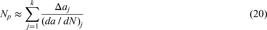
Based on the proposed SFC growth rate model, the fatigue crack propagation life can be estimated by integrating the inverse of the crack growth rate over the crack length range. The propagation life from an initially detectable short-crack length


Model validation and discussion
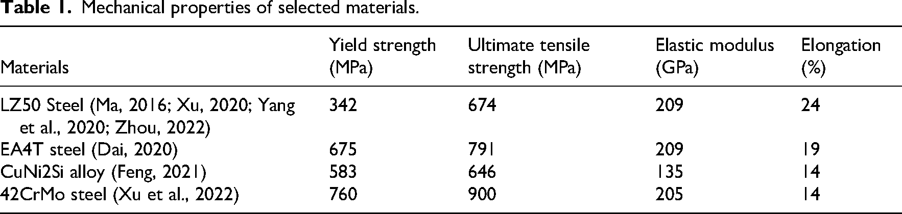
To evaluate the descriptive capability and applicability of the proposed short-crack growth model in this study, multiple sets of fatigue test data under different loading conditions were selected, covering typical metallic materials such as LZ50 steel (Ma, 2016; Xu, 2020; Yang et al., 2020; Zhou, 2022), EA4T steel (Dai, 2020), CuNi2Si alloy (Feng, 2021), and 42CrMo steel (Xu et al., 2022). These materials are widely used in various industries, including transportation, energy equipment, aerospace electronics, and mechanical manufacturing, exhibiting strong representativeness and broad application scenarios. By comparing the simulation results with the experimental data, the accuracy and robustness of the proposed model in describing the short-crack growth process were evaluated. Based on the typical mechanical property parameters of the materials listed in Table 1, the short-crack propagation behavior of these materials under different loading conditions was modeled and calculated, and the simulation results were compared and analyzed against the experimental data. To investigate the fatigue crack growth behavior of different materials under various loading conditions, multiple types of test specimens were designed, and their geometrical configurations are shown in Figure 6.
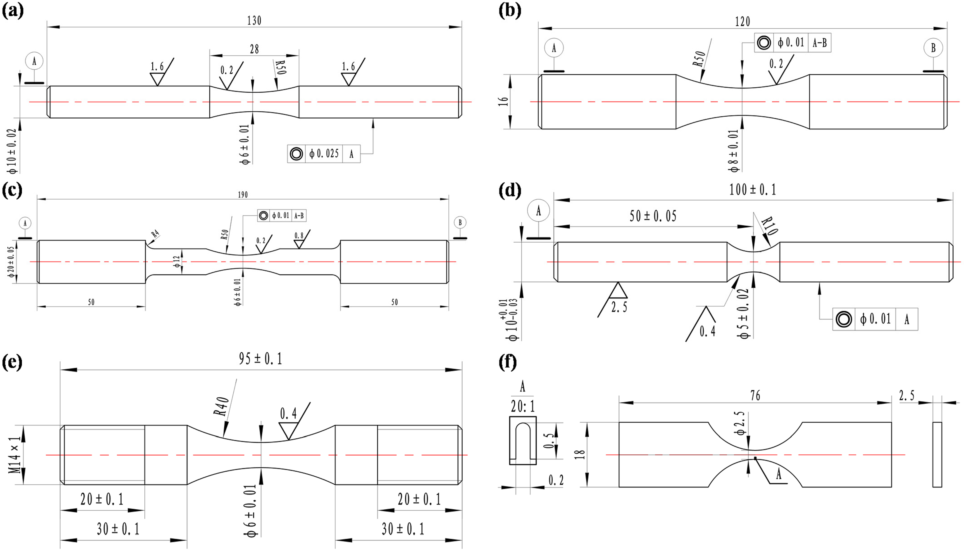
Geometrical configurations of fatigue test specimens under different materials and loading conditions: (a) LZ50 under different load sequences, (b) LZ50 under two loading frequencies, (c) LZ50 and EA4T under different loading paths, (d) CuNi2Si under rotating bending, (e) CuNi2Si under axial tension–compression, and (f) 42CrMo under axial loading.
Mechanical properties of selected materials.
To provide a clearer description of the validation datasets, the main experimental conditions used in this study are summarized in Table 2. Since the datasets were collected from published literature, the loading parameters and experimental details were extracted from the corresponding references as completely as possible. For several datasets, some information, such as repeated-test scatter, surface roughness, or complete fatigue-life distribution, was not fully reported in the original studies. These unavailable details are therefore marked as “not reported” and are discussed as one of the limitations of the present validation.
Summary of experimental datasets and loading conditions used for model validation.
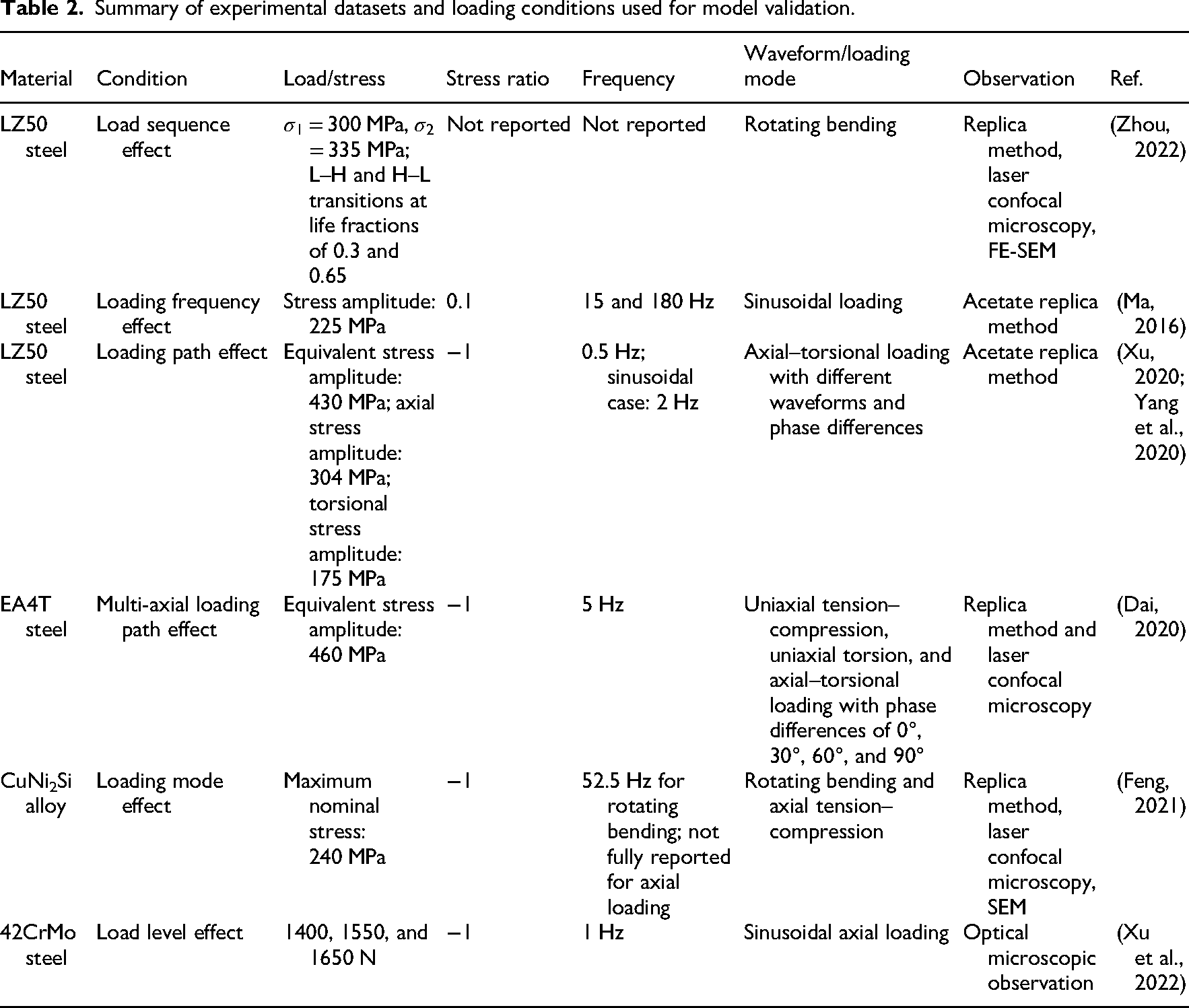
The collected datasets cover different load sequences, loading frequencies, loading paths, loading modes, and load levels. Therefore, they can be used to evaluate the descriptive capability of the proposed model under different prescribed loading conditions. It should be noted that the present validation focuses mainly on the short-crack propagation stage after a detectable crack is formed. Due to the inconsistency of crack initiation criteria and the incomplete reporting of total fatigue life in some literature datasets, the present study mainly evaluates crack growth rate prediction and propagation behavior rather than complete fatigue life scatter.
LZ50 steel is a medium-carbon steel with good comprehensive mechanical properties and excellent machinability. It is commonly used for shaft components in railway vehicles, such as axles and crankshafts. EA4T steel is a type of low-alloy high-strength steel characterized by high strength, high toughness, and good hardenability. It is widely applied in high-speed train axles and other high-speed rotating components. CuNi2Si alloy is a precipitation-strengthened copper alloy that combines high strength, excellent electrical conductivity, and good wear resistance. It is extensively used in aerospace electronics, electrical connectors, and precision elastic components. 42CrMo steel is a typical quenched and tempered alloy structural steel with high strength, high toughness, and good heat treatment performance. It is commonly used for critical components subjected to high loads, such as transmission shafts, gears, and couplings. These materials are frequently subjected to various forms of cyclic loading during service, and an in-depth understanding of their fatigue properties is of great significance for the structural safety assessment of engineering components.
Fitting of short-crack growth rates under different load sequence effects
To investigate the effect of different load sequences on the SFC growth behavior, Zhou (2022) conducted short-crack growth experiments on LZ50 steel specimens using a QBWP-6000J rotary bending fatigue testing machine. The shape and dimensions of the specimen are shown in Figure 6(a). This experimental system established a four-point bending loading environment through a simply supported beam constraint and weight loading method, enabling stable cyclic stress control. In order to capture crack evolution information, a laser confocal microscope was employed to observe the surface replica film during the test, recording the processes of crack initiation and propagation. The fracture surface morphology was examined using a JSM-7800F FE-SEM to obtain high-resolution images of crack initiation sites and propagation paths for further analysis of crack behavior characteristics. Prior to testing, the specimen surfaces were subjected to multiple preparation processes. The curved section of the specimen was sequentially polished using 1000, 2000, and 3000 grit sandpapers, followed by mirror polishing with a diamond paste of 2.5 μm particle size to eliminate surface scratches and improve the observability of crack initiation. To reveal the relationship between crack propagation and microstructure, metallographic etching was performed on the specimen surface before the replica test. A 4% nitric acid alcohol solution was used as the etchant to highlight GBs and microstructural features. Regarding the loading scheme, two typical stress amplitudes were selected as cyclic load levels: a low load of σ1 = 300 MPa and a high load of σ2 = 335 MPa. Based on the average fatigue life under single-load conditions, two loading sequence schemes—“low–high (L–H)” and “high–low (H–L)”—were designed by switching loads at different life fractions. Rotating bending fatigue tests were conducted under both loading sequences.
Taking the LZ50 steel specimens under different load sequence conditions as the research object, the development process of the proposed short-crack growth rate model is illustrated in this study, which is equally applicable to other materials and loading conditions examined in this paper. There are two typical types of microstructural barriers in the microstructure of this material, namely ferrite GBs and pearlite banded structures. During the early stage of crack propagation, the first type of microstructural barrier (ferrite GBs) plays a dominant role in hindering crack growth, especially before the crack fully penetrates this type of barrier, where the resistance effect is particularly significant. After the crack tip crosses the first type of barrier, its obstructive effect gradually weakens, and the crack propagation enters a stage dominated by the second type of microstructural barrier (pearlite banded structure), during which the crack growth mechanism and behavior characteristics change accordingly. In addition, multi-stage loading conditions were applied during the tests. Different loading conditions not only altered the characteristics of the crack tip driving force but also led to variations in the far-field strain energy density ΔS. Notably, after the crack tip breaks through the first type of microstructural barrier, the far-field loading level changes, and the crack propagation behavior exhibits obvious stage-dependent characteristics. Therefore, the proposed short-crack growth rate model in this study considers the effects of both types of microstructural barriers and the different loading stages. The mathematical expressions of the crack growth rate can be written separately as follows


Based on the modified Ramberg–Osgood relation and the cyclic hysteresis loop equation, the far-field cyclic strain energy density is expressed in a constant-coefficient form as (Yang et al., 2020)


The revised short-crack growth rate model simplifies to


By transposing G1 and G2 to the left-hand side and taking the logarithm of both sides of the transformed equation, we obtain


According to the above equation, a good linear relationship is observed between
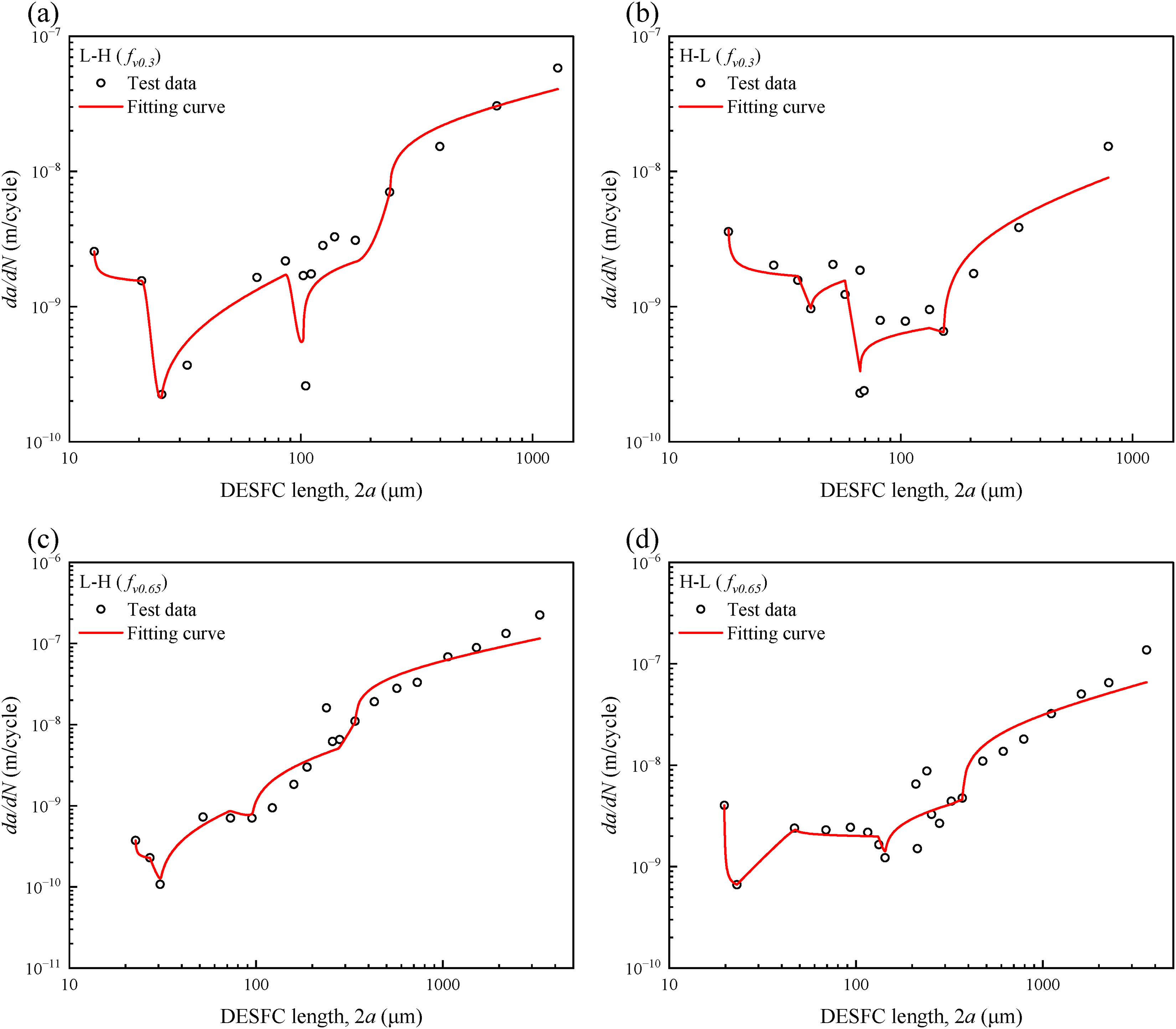
Fitting results of the short-crack growth rate model under different load sequences and life fractions: (a) L–H loading with a life fraction of 0.3, (b) H–L loading with a life fraction of 0.3, (c) L–H loading with a life fraction of 0.65, and (d) H–L loading with a life fraction of 0.65.
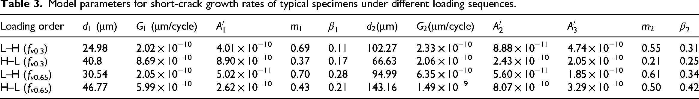
Model parameters for short-crack growth rates of typical specimens under different loading sequences.
Fitting of short-crack growth rates under different loading frequencies
To investigate the effect of different loading frequencies on the SFC growth behavior, Ma (2016) conducted short-crack growth replica tests on LZ50 steel under two loading frequencies of 15 and 180 Hz. The specific shape and dimensions of the specimen are shown in Figure 6(b). The fatigue tests were performed under stress-controlled loading conditions, with a stress amplitude of 225 MPa, a stress ratio of R = 0.1, and a sinusoidal waveform. The test at a loading frequency of 15 Hz was carried out using an MTS 809 axial–torsional composite fatigue testing machine, while the test at a loading frequency of 180 Hz was conducted using a GPS-100 high-frequency fatigue testing machine. During the tests, the acetate replica technique was employed to periodically replicate the surface crack growth behavior of the specimens, enabling the capture of short-crack initiation and propagation processes. Figure 8 presents the fitting results of the proposed short-crack growth rate model and the experimental data under two different loading frequency conditions.
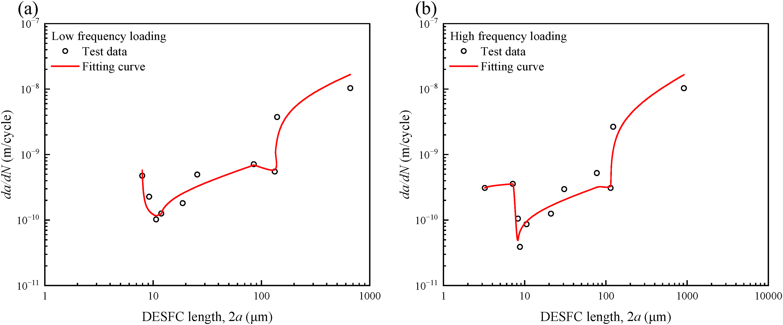
Fitting results of the short-crack growth rate model under different loading frequencies: (a) 15 Hz loading frequency and (b) 180 Hz loading frequency.
Fitting of short-crack growth rates under different loading paths
To investigate the influence of different loading paths under various waveform shapes and phase differences on the SFC growth behavior, Xu (2020) conducted short-crack growth experiments on LZ50 steel. The specific shape and dimensions of the specimen are shown in Figure 6(c). The tests were performed on an MTS 809AT axial–torsional composite fatigue testing machine, under combined axial and torsional loading conditions. During the tests, the acetate replica technique was employed to periodically replicate the minimum radius area of the specimen, aiming to capture key information such as crack initiation location, propagation path, and growth behavior. The loading parameters were set as a stress ratio of R = −1, an equivalent stress amplitude of 430 MPa, and an axial-to-torsional stress amplitude ratio of
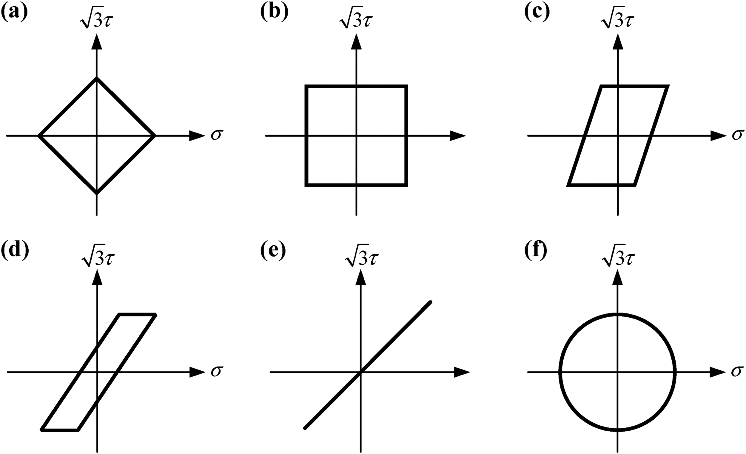
Stress paths under different loading waveforms and phase differences: (a) triangular wave with 90° phase difference, (b) square wave with 90° phase difference, (c) square wave with 60° phase difference, (d) square wave with 30° phase difference, (e) square wave with 0° phase difference, and (f) sinusoidal wave with 90° phase difference.
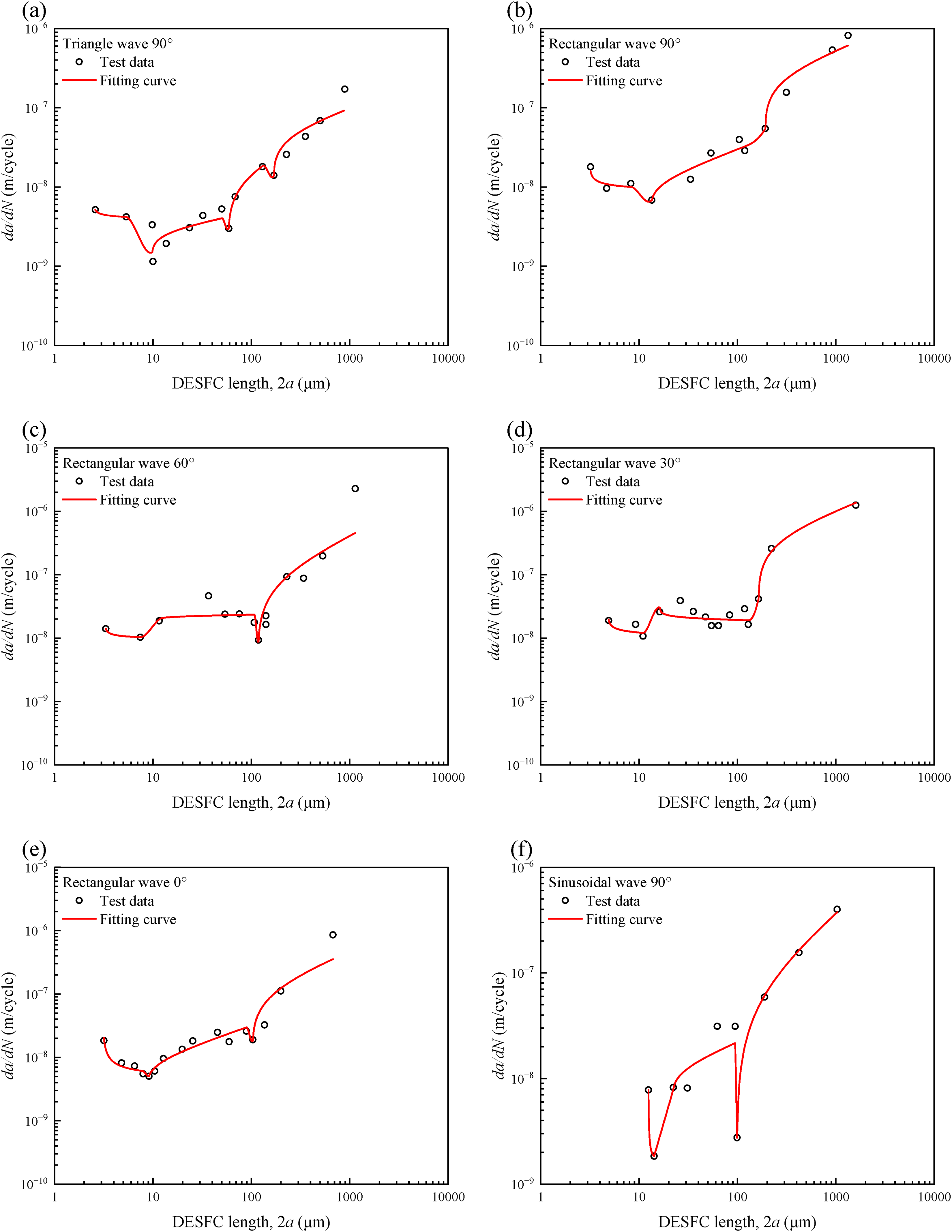
Fitting results of the short-crack growth rate model under different loading waveforms and phase differences: (a) triangular wave with 90° phase difference, (b) rectangular wave with 90° phase difference, (c) rectangular wave with 60° phase difference, (d) rectangular wave with 30° phase difference, (e) rectangular wave with 0° phase difference, and (f) sinusoidal wave with 90° phase difference.
Similarly, Dai (2020) conducted short-crack growth experiments on EA4T steel. The specific shape and dimensions of the specimen are shown in Figure 6(c). All fatigue tests were performed using an MTS 809.25 axial–torsional composite fatigue testing machine. During the experiments, both ends of the specimen were clamped using MTS hydraulic grips, with the upper end fixed and the lower end subjected to cyclic loading. The loading waveform was sinusoidal for all tests. A total of six different loading paths were designed in the experiments, including uniaxial tension–compression loading, uniaxial torsional loading, and axial–torsional multi-axial loading with four different phase differences (0°, 30°, 60°, and 90°). The stress trajectories corresponding to each loading path are shown in Figure 11. The loading parameters for all tests were set as an equivalent stress amplitude of 460 MPa, with stress ratios of R = −1 for both axial and torsional loading, and a specified axial-to-torsional stress amplitude ratio. The loading frequency was f = 5 Hz. During the tests, an Olympus LEXT OLS4100 laser confocal microscope was used to observe and collect surface crack data. In addition, the acetate replica technique was applied to periodically replicate the minimum radius area of the specimen, in order to record crack initiation locations, propagation paths, and growth behaviors, providing data support for subsequent analysis of crack growth mechanisms. Figure 12 presents the fitting results of the proposed short-crack growth rate model and the experimental data of EA4T steel under different loading paths.
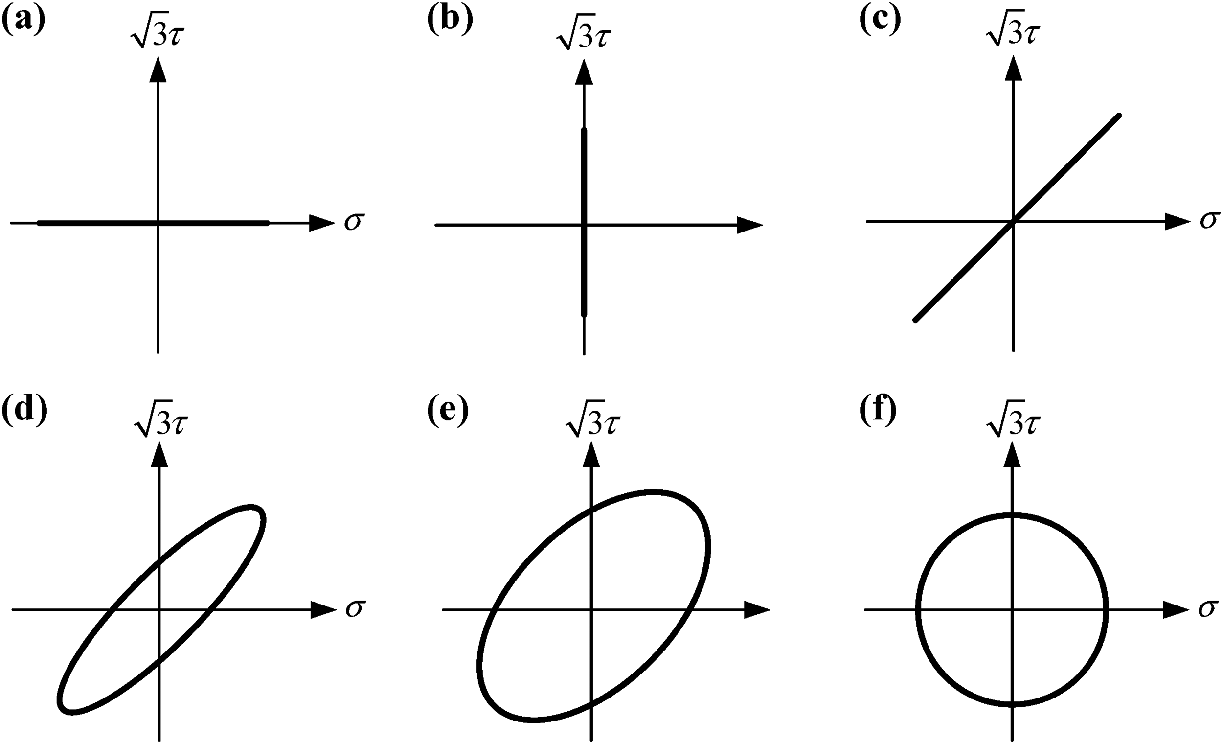
Stress paths under uniaxial and biaxial loading conditions with different phase differences: (a) uniaxial tension–compression, (b) uniaxial torsion, (c) biaxial loading with 0° phase difference, (d) biaxial loading with 30° phase difference, (e) biaxial loading with 60° phase difference, and (f) biaxial loading with 90° phase difference.
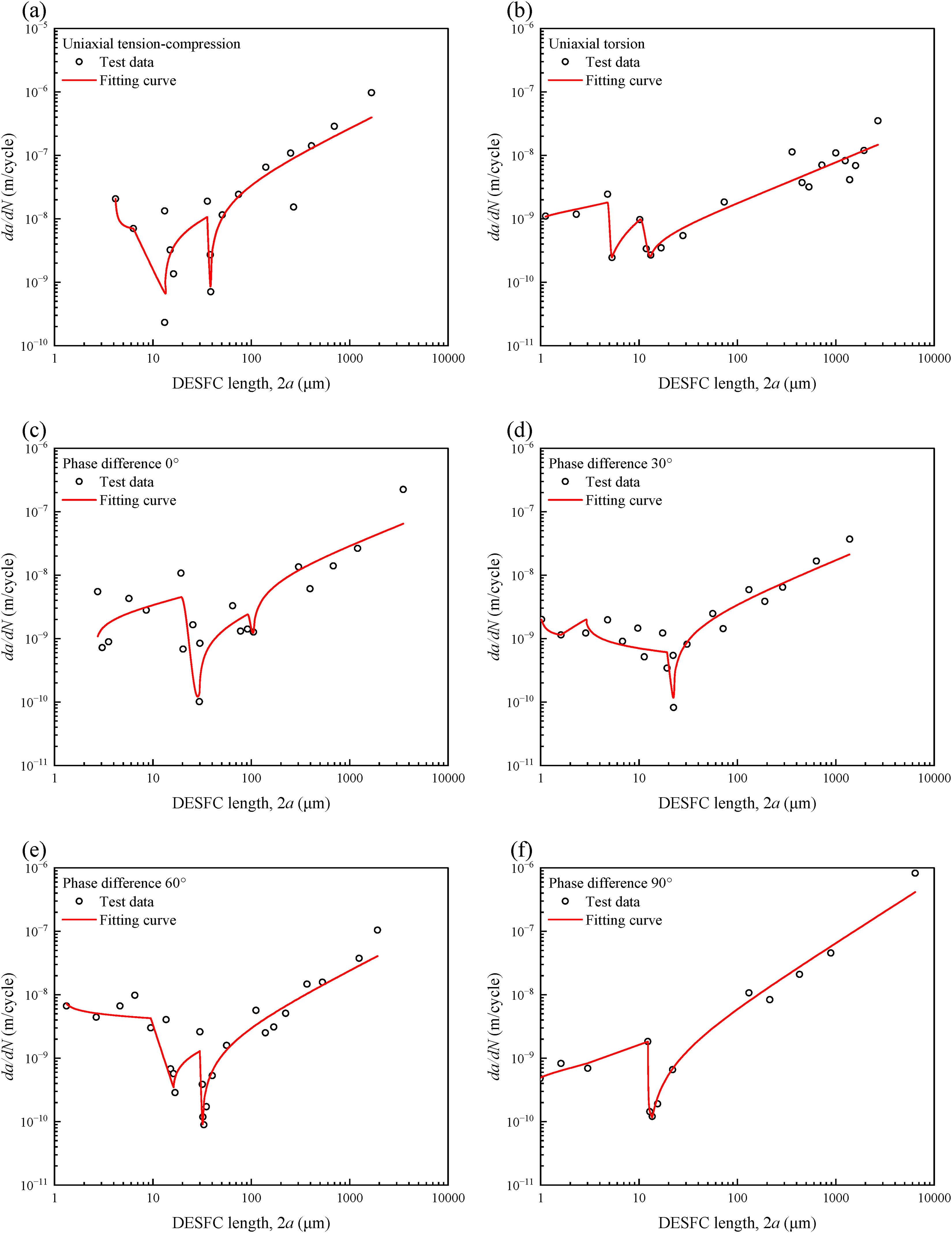
Fitting results of the short-crack growth rate model under different loading waveforms and phase differences: (a) uniaxial tension–compression, (b) uniaxial torsion, (c) biaxial loading with 0° phase difference, (d) biaxial loading with 30° phase difference, (e) biaxial loading with 60° phase difference, and (f) biaxial loading with 90° phase difference.
Fitting of short-crack growth rates under different loading forms
To investigate the effect of different loading modes on the SFC growth behavior, Feng (2021) conducted short-crack growth experiments on CuNi2Si alloy. The specific shapes and dimensions of the specimens are shown in Figure 6(d) and (e), corresponding to rotary bending loading and axial tension–compression loading conditions, respectively. The rotary bending fatigue tests were carried out using an RBE4-3150-V1 rotary bending fatigue testing machine with a loading frequency of 52.5 Hz, while the axial tension–compression fatigue tests were performed on a Rumul-250 high-frequency fatigue testing machine. All experiments were conducted at room temperature with a stress ratio of R = −1, a maximum nominal stress of 240 MPa, and a sinusoidal loading waveform. During the tests, an Olympus OLS4100 laser confocal microscope was used to observe the surface crack growth process and collect experimental data. To further analyze the crack initiation characteristics and propagation path, the acetate replica technique was employed to periodically replicate the minimum radius area of the specimen. After the tests, the fracture surface morphologies of the specimens were observed using a JSM-6610LV SEM to obtain information on crack initiation sites, propagation characteristics, and fracture mechanisms. Figure 13 presents the fitting results of the proposed short-crack growth rate model and the experimental data of CuNi2Si alloy under different loading modes.
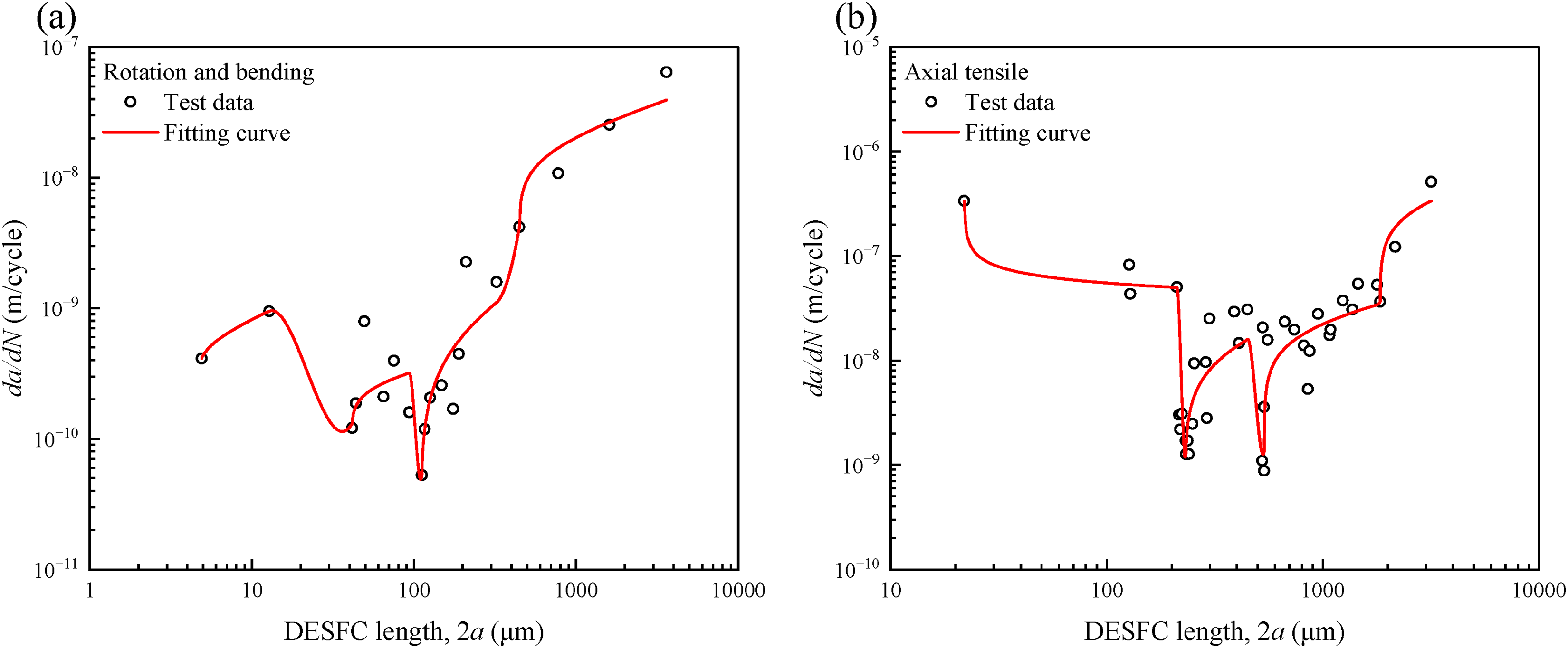
Fitting results of the short-crack growth rate model for CuNi2Si alloy under different loading forms: (a) rotating bending and (b) axial tension–compression.
To investigate the influence of different loading modes on the SFC growth behavior, Xu et al. (2022) conducted short-crack growth experiments on 42CrMo steel. The specific shape and dimensions of the specimen are shown in Figure 6(f). In order to induce crack initiation at specific locations and reduce the randomness and workload of crack observation, two small notches with dimensions of 0.5 mm × 0.2 mm were prefabricated on both sides of the specimen centerline. The fatigue tests were conducted under sinusoidal loading conditions with a loading frequency of 1 Hz and a stress ratio of R = −1, at room temperature and in an air environment. Crack length and its corresponding growth rate were measured under three different load levels of 1400, 1550, and 1650 N. The specimen surface was subjected to pregrinding, fine grinding, and polishing treatments to eliminate machining marks and ensure the clarity of crack observation. Crack initiation and propagation processes were observed using a microscope equipped with the microfatigue testing machine. In addition, to analyze the influence of material microstructure on crack growth behavior, the specimen surface was etched with a 3% nitric acid alcohol solution after testing, to reveal the metallographic features and assist in the analysis of crack growth mechanisms. Figure 14 presents the fitting results of the proposed short-crack growth rate model and the experimental data of 42CrMo steel under different load levels.
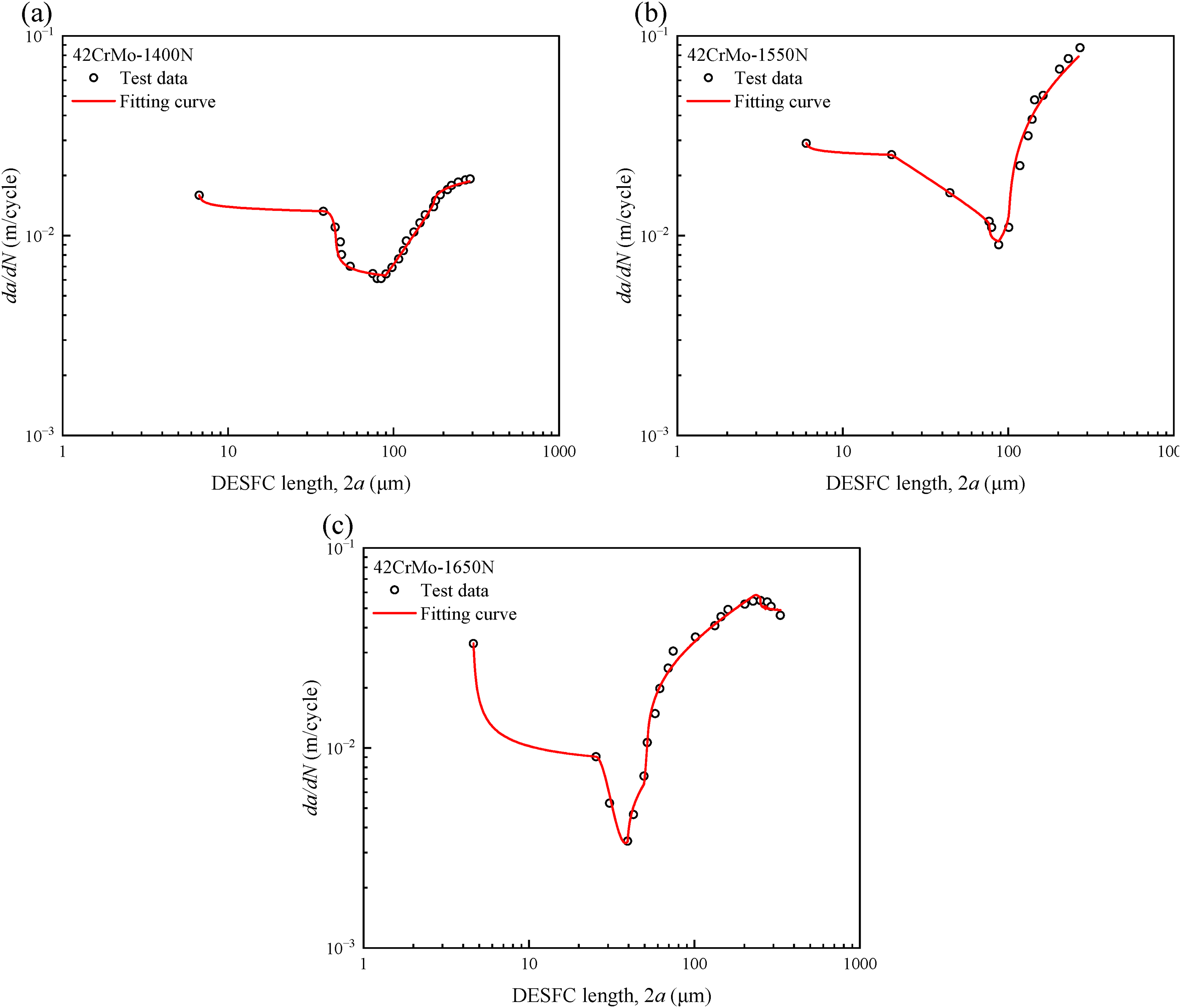
Fitting results of the short-crack growth rate model for 42CrMo steel under different load levels: (a) 1400 N, (b) 1550 N, and (c) 1650 N.
Results’ discussion and statistical evaluation
To further evaluate the applicability and reliability of the proposed SFC growth rate model, the predicted results were compared with the experimental data under different materials and loading conditions. The validation cases cover different load sequences, loading frequencies, loading paths, loading modes, and load levels. Overall, the proposed model can reasonably capture the nonlinear evolution of short-crack growth rates and the stage-dependent characteristics of crack propagation under multi-condition loading.
For the load sequence effect shown in Figure 7, the L–H and H–L loading sequences exhibit different crack growth behaviors due to the influence of prior loading history. In the L–H loading cases, the increase in the applied stress level promotes crack acceleration after load transition. In the H–L loading cases, the previous high-load history affects the subsequent crack growth response even after the load is reduced. These results indicate that short-crack growth is sensitive to load sequence and loading history. This trend is consistent with the stage-dependent change in crack-driving force considered in the proposed model.
For the loading frequency effect shown in Figure 8, the crack growth behaviors at 15 and 180 Hz are reasonably reproduced by the proposed model. The experimental results indicate that the crack growth rate under lower-frequency loading is generally higher than that under higher-frequency loading. This may be related to the longer interaction time between the crack tip and the surrounding environment at lower frequency, which can promote crack-tip oxidation, local damage accumulation, and environmental interaction. In contrast, higher-frequency loading reduces the available time for environmental interaction, leading to a relatively lower crack growth rate under the same nominal stress amplitude.
For the loading path effect shown in Figures 10 and 12, short-crack growth under multi-axial loading is strongly affected by waveform and phase difference. Non-proportional loading paths generally lead to more complex crack propagation behavior than proportional loading paths. With increasing phase difference, additional cyclic hardening, shear-normal stress interaction, and crack path deflection may occur, thereby accelerating short-crack growth and increasing the fluctuation of crack growth rate. This behavior reflects the necessity of incorporating loading-path-dependent crack-driving effects and microstructural resistance into short-crack growth modeling.
For the loading mode effect shown in Figure 13, the crack growth behaviors under rotating bending and axial tension–compression loading are different. Under rotating bending, the surface stress gradient and bending-induced stress concentration may promote crack initiation and early propagation. Under axial tension–compression loading, the stress state is more uniform, but crack propagation may be more sensitive to local microstructural features, resulting in greater scatter in crack growth rate. The relatively larger deviations observed in some local regions indicate that loading-mode-dependent crack growth is also affected by local microstructural heterogeneity and crack path variation.
For the load level effect shown in Figure 14, the crack growth rate of 42CrMo steel increases with increasing load level. Higher load levels provide a larger crack-tip driving force and promote faster crack propagation. This result indicates that the crack-tip driving force plays a dominant role in the load-level-dependent growth behavior of 42CrMo steel.
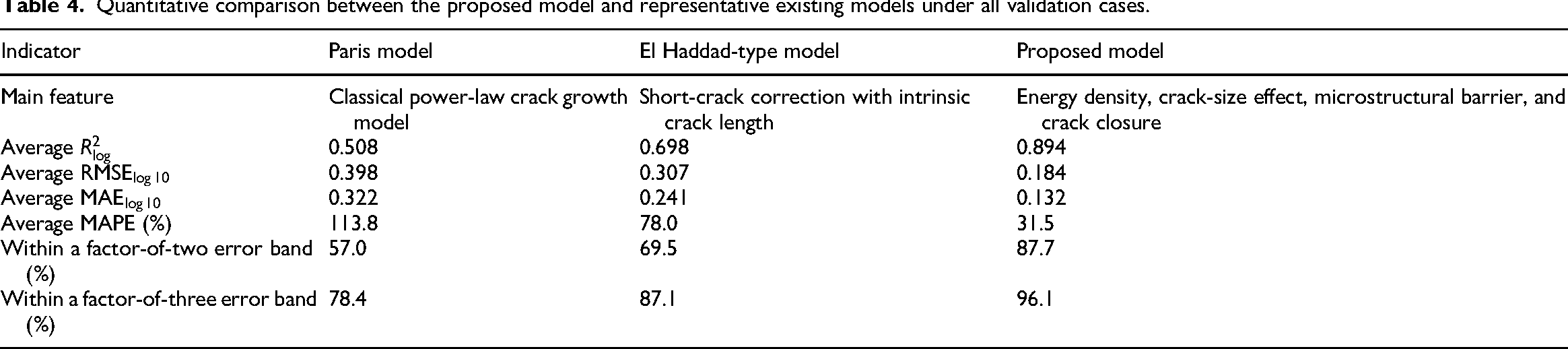
To further compare the proposed model with the representative existing models, the Paris model and the El Haddad-type short-crack correction model were selected as baseline models. The Paris model represents the classical long-crack-growth formulation based on LEFM, while the El Haddad-type model represents a typical short-crack correction method considering the intrinsic crack length effect. Because complete stress intensity factor solutions and threshold parameters were not available for all literature-reported datasets, the two baseline models were fitted in equivalent forms for each validation case. The parameters of both baseline models were identified by least-squares fitting on a logarithmic scale. It should be noted that Newman closure-based models and
The quantitative comparison results are summarized in Table 4. A total of 23 validation cases and 405 experimental data points were evaluated. The Paris model gives an average
Quantitative comparison between the proposed model and representative existing models under all validation cases.
To further visualize the comparative performance of different models, the experimental and predicted crack growth rates obtained by the Paris model, the El Haddad-type model, and the proposed model are plotted in Figure 15. Compared with the Paris and El Haddad-type models, the data points predicted by the proposed model are more concentrated around the perfect agreement line, and a higher proportion of points falls within the factor-of-two and factor-of-three error bands. This indicates that the proposed model provides a more reliable description of SFC growth behavior under different loading conditions.
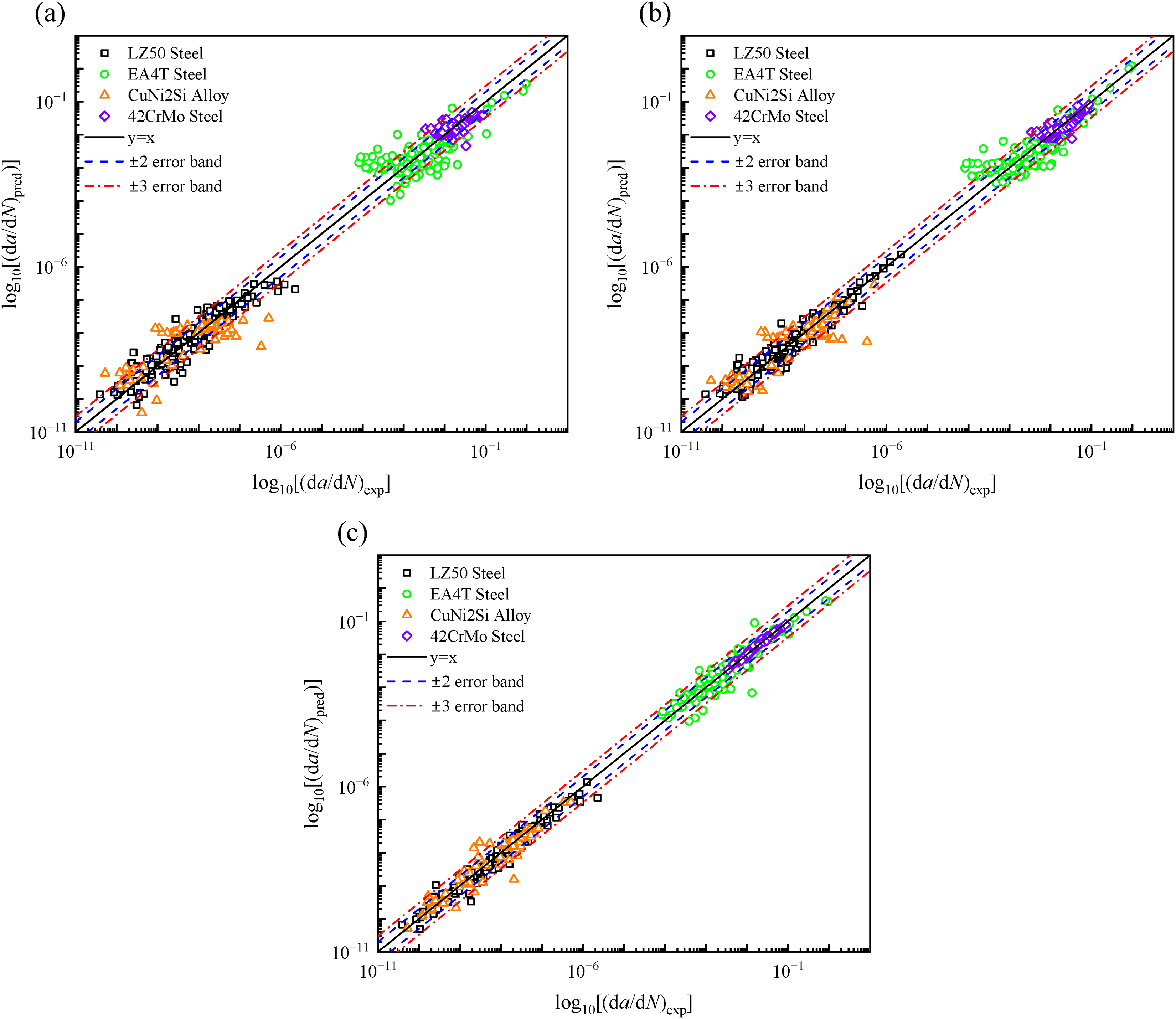
Experimental–predicted comparison of short fatigue crack growth rates for different models: (a) Paris model, (b) El Haddad-type model, and (c) proposed model.
It should be noted that the fitting accuracy varies among different loading cases. Relatively better fitting performance is observed in the load-level-dependent cases of 42CrMo steel, where the crack growth behavior is mainly governed by the external driving force. In contrast, larger deviations are observed in some multi-axial loading and loading-mode-dependent cases. These deviations may be attributed to the strong local sensitivity of short-crack growth to microstructural heterogeneity, crack deflection, crack coalescence, GB resistance, and measurement scatter from the replica method. The replica method may introduce measurement uncertainty due to surface replication quality, image resolution, crack-tip identification, and the selected measurement interval, especially in the early short-crack stage.
Therefore, the proposed model should be regarded as a physically interpretable and engineering-oriented framework for describing the general evolution trend of SFC growth under different prescribed loading conditions, rather than a purely empirical curve-fitting equation. Nevertheless, some limitations remain. First, the current validation is mainly based on published experimental datasets, and some experimental details, such as measurement uncertainty, repeated-test scatter, crack-length resolution, and complete microstructural statistics, are not fully available. In particular, the replica method may introduce additional uncertainty due to surface replication quality, image resolution, crack-tip identification, and the selected measurement interval, which may partly contribute to the scatter of experimental
Conclusion
In this study, a multi-scale SFC growth rate model was proposed to describe the nonlinear and stage-dependent propagation behavior of SFCs under different loading conditions. The model couples crack-tip strain energy density, crack-size effect, microstructural barrier resistance, and crack closure correction, providing a physically interpretable framework for short-crack growth assessment. The main conclusions are as follows:
SFC growth is strongly affected by microstructural features, crack-size effects, and loading conditions. Crack arrest, re-initiation, deflection, coalescence, and growth-rate fluctuation are typical characteristics of short-crack propagation. These behaviors indicate that short-crack growth cannot be fully described by conventional long-crack models based only on LEFM. Compared with the existing short-crack growth models, the proposed model introduces a microstructural barrier penetration function and a crack-opening correction factor. The penetration function describes the gradual interaction between the crack tip and microstructural obstacles, while the crack-opening correction modifies the effective crack-driving force during cyclic loading. Therefore, the proposed model can better represent the constrained and nonlinear propagation behavior of SFCs. The model was validated using literature-reported experimental datasets for LZ50 steel, EA4T steel, CuNi2Si alloy, and 42CrMo steel under different load sequences, loading frequencies, loading paths, loading modes, and load levels. Quantitative evaluation shows that the average The proposed model is mainly applicable to fatigue assessment problems in which short-crack initiation and early propagation occupy an important portion of fatigue life, such as railway axles, rotating shafts, mechanical transmission components, and metallic structures subjected to sequential or multi-axial loading. The model provides a useful tool for short-crack growth analysis and propagation-life estimation after the formation of a detectable crack.
Nevertheless, several limitations remain. First, the validation datasets used in this study were collected from published literature, and some experimental details, such as repeated-test scatter, measurement uncertainty, and complete microstructural statistics, were not fully available. Second, although microstructural barrier effects are considered, some barrier-related parameters are still obtained by fitting, and their uniqueness and transferability require further investigation. Third, the present validation mainly focuses on constant-amplitude or prescribed loading conditions. Further studies under random loading, spectrum loading, and real service loading histories are needed to improve the robustness and applicability of the proposed model.
Footnotes
Author contributions
Funding
The authors disclosed receipt of the following financial support for the research, authorship, and/or publication of this article: This work was supported by the National Natural Science Foundation of China (Grant No. 52365014), the Natural Science Foundation of Inner Mongolia Autonomous Region (Grant No. 2025QN05040), and the Science and Technology Major Project of Inner Mongolia Autonomous Region (Grant No. KCX2024010).
Declaration of conflicting interests
The authors declared no potential conflicts of interest with respect to the research, authorship, and/or publication of this article.
Data availability
Data will be made available on request.