






Abstract
The irradiation effect on the fracture toughness and the energy release rate in metallic materials leads to typical cracking behaviors in structural components of reactors. In this paper, the fracture toughness degradation mechanism and cracking behavior in irradiated face-centered cubic (fcc) metals are numerically analyzed using a newly developed phenomenological constitutive model. By characterizing the irradiation-induced plastic flow behavior through variations in the hardening modulus and taking into account the neutron-irradiation strain subjected to irradiation doses, a phenomenological constitutive model for irradiated fcc metals is constructed based on the framework of incremental plasticity theory. The constitutive model is validated as universally applicable over a wide irradiation range by comparing simulation results with experimental data. Furthermore, using the presented constitutive model, cracking simulations are conducted under various irradiation conditions. The numerical results show that the plastic zone near the crack tip decreases nonlinearly as the irradiation extent increases. Irradiation-induced degradation of fracture toughness is thoroughly interpreted through the influence mechanism of irradiation dose on the plastic zone near the crack tip. In addition, the irradiation effect on cracking is quantitatively analyzed by calculating the J-integral at the crack tip. The energy release rate during crack propagation increases logarithmically with increasing irradiation doses, indicating that irradiation accelerates cracking in fcc metals. As an application example, the presented constitutive model is utilized to estimate the onset condition for crack propagation in the fcc metal matrix. This study lays a foundation for investigating irradiation resistance performance and evaluating the failure of structural components in reactors.
Introduction
Mechanical properties of structural components in reactors are significantly altered during irradiation (Arsenlis et al., 2004; Dai et al., 1994; Gussev et al., 2012; Krishna et al., 2010), including decreased fracture toughness, increased yield strength, reduced plasticity under high doses, reduced ductility, and so on (Chen et al., 2012, 2020; Hall and Flinn, 2010; Ming et al., 2020). Accordingly, irradiation is a crucial factor influencing the cracking failure of in-pile materials. As a widely used structural material within reactors, face-centered cubic (fcc) metals are commonly used to manufacture cladding, cooling pipes, heat exchangers, and so on. Thus, analyzing the typical cracking behavior in irradiated fcc metals is crucial for reactor safety.
The irradiation-induced cracking behavior can be assessed utilizing the energy criterion, which is based on fracture toughness and the energy release rate (Chen et al., 2012; Ersoy et al., 2014; Liu et al., 2020). By analyzing whether the energy release rate reaches the fracture toughness, issues related to crack initiation, propagation and arrest can be studied in irradiated fcc metals. The prerequisite for analyzing irradiation-induced cracking is to obtain the fracture toughness and determine the energy release rate under different irradiation doses. Researchers have developed various crystal plasticity models (Xiao et al., 2015), molecular dynamics models (Morales et al., 2024) and data-driven irradiation constitutive models (Gussev et al., 2012) to characterize the influence of irradiation on mechanical properties, such as the yield stress and the irreversible deformation, revealing the temperature dependence and the irradiation dose dependence of fracture toughness (Azihari et al., 2024; Burchell and Strizak, 2014; Jia and Dai, 2006; Kim and Kim, 2024). But the complete irradiation failure process—from deformation and yield to damage evolution, crack initiation, and macroscopic cracking—has not been explicitly characterized or numerically simulated. How neutron dose affects key fracture parameters (e.g. the energy release rate) remains unclear.
To determine the influencing mechanism of irradiation on the energy release rate in fcc metals, a universal irradiation constitutive model that can rapidly and accurately describe the true stress–strain relationships over a wide irradiation range should be developed. Shi et al. (2022) indicated that defect strengthening coefficients were overestimated by classical hardening formulations, and the irradiation hardening model at the regime of high doses needed improvement through the integration of more precise descriptions of irradiation-induced microstructure evolution and the associated defect accumulation kinetics. That is why the constitutive relationship under high irradiation doses is difficult to reproduce precisely with the microstructure-evolution model (Chatterjee et al., 2016; Deo et al., 2008; Erinosho and Dunne, 2015; Farrell et al., 2004; Lee et al., 2014; Li et al., 2014; Rys and Skoczen, 2017; Wu et al., 2022; Yu and Shen, 2016). Erinosho and Dunne (2015) revealed strain localization and failure in irradiated Zircaloy using crystal plasticity. Li et al. (2014) predicted irradiation hardening via dislocation dynamics. Yu and Shen (2016) identified, at the atomic scale, the role of grain boundaries as point defect traps. Despite their mechanistic insights, these models typically require a large number of microstructural parameters and involve high computational costs, making them impractical for direct application to component-scale cracking analysis.
Given that irradiation behaviors are inherently multi-scale while the effects are manifested at the component level, a universal phenomenological constitutive model is effective for the cracking analysis of irradiated fcc metals (Alabdullah and Ghoniem, 2020). And the macro variables in this model must be correlated with the evolution of irradiation-induced microstructures. Existing phenomenological models for irradiated metals are typically validated only at low to moderate irradiation doses (Hall, 2010) and focus primarily on homogeneous deformation behavior (e.g. creep and swelling). They lack direct coupling with fracture mechanics parameters, rendering them incapable of analyzing irradiation-induced cracking.
Taken together, by developing a phenomenological constitutive model for the fcc metals and numerically implementing it in the finite element method (FEM), this work simulated the variation of energy release rate induced by irradiation and analyzed cracking behaviors of fcc metals under different neutron doses. The presented model incorporates mechanical variables originating from the microstructural evolution subjected to irradiation doses (Chen and Song, 2022; Hall, 2010; Moladje et al., 2020; Pham and Kim, 2024), and describes the irradiation-induced mechanical properties over a wide irradiation range. The irradiation effect on the plastic zone near the crack tip is revealed for interpreting the degradation mechanism of fracture toughness in irradiated fcc metals. Based on the presented constitutive model, the fracture parameter of fcc metals under different neutron doses can be numerically calculated, and utilized for analyzing the irradiation effect on the cracking behavior according to the energy criterion (Li et al., 2016).
Compared to crystal plasticity and molecular dynamics models, which provide detailed microstructure evolution but are computationally expensive and difficult to scale to component-level cracking analysis, the present phenomenological model offers high computational efficiency and direct applicability to engineering-scale problems. Besides, the present model is validated in a wide irradiation range and directly linked to the J-integral for cracking assessment, verifying its novelty and practical value.
This study aims to develop a numerical approach for investigating the cracking behavior in irradiated fcc metals. Section “Methodology” presents the derivation of an irradiation phenomenological constitutive model and the numerical implementation method. Several numerical samples are simulated and validated against experimental data to verify the model's feasibility and predictive accuracy. In Section “The effect of irradiation doses on the cracking behavior,” the effects of irradiation on the plastic zone near the crack tip and the energy release rate are discussed by simulations of a central crack model. The irradiation-induced variation of the plastic zone interprets the degradation of fracture toughness in irradiated materials. In Section “Cracking analysis of an in-pile component,” the present method is further applied to the cracking analysis of a local dispersion nuclear fuel model. Finally, some conclusions are summarized in Section “Conclusions.”
Methodology
The phenomenological constitutive model for irradiated fcc metals
This section constructs a phenomenological constitutive model for irradiated fcc metals in strict accordance with the framework of incremental plasticity theory (Zhou, 2010; Boyne et al., 2013). The contribution of irradiation-induced microstructure evolution on the constitutive relationship is represented using the irradiation flow stress and neutron-irradiation strain in the model. In this way, the irradiation effects on physical fields are taken into account in the calculation of each incremental tensor.
In irradiated fcc metals, the total strain tensor is composed by two parts, namely the reversible stain

The reversible strain arises from the elastic behavior throughout the entire deformation process, while the irreversible stain can be decomposed into the inherent plastic term and the irradiation term. The inherent plastic term represents the intrinsic plasticity of metallic materials, existing when the stress exceeds the yield strength. Whereas the neutron-irradiation strain refers to the irreversible strain term induced by irradiation-induced microstructure changes (Hall, 2010). Thus the variation of total strain in Equation (1) is extended as:

Due to the irreversible deformation caused by irradiation, the equivalent stress needs to reach an elevated yield strength to enter the plastic stage. Through characterizing strain tensors of the elastic term, the irradiation term and the plastic term in Equation (2), irradiation-dependent physical states can be derived according to the incremental plasticity theory. The constitutive equations before and after yielding are represented separately. Ultimately, the phenomenological constitutive model for irradiated fcc metals is systematically determined and listed in Table 1. The detailed derivation is demonstrated in Appendix A.
The phenomenological constitutive model for irradiated fcc metals.
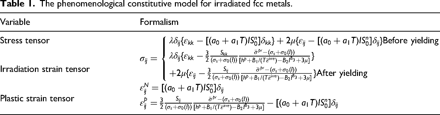
For the expressions in Table 1,
As the present model adopts a classical (local) plasticity framework, the material response at a material point depends only on the local strain–stress state (Kim and Kim, 2024; Robertson et al., 2026). The strain gradient effect, which may become significant near crack tips where strain fields vary sharply over small distances (Martínez-Pañeda and Fleck, 2019), is therefore not considered. This assumption is consistent with standard engineering fracture mechanics practice (Rice, 1968) and is subsequently justified by the model's successful prediction of macroscopic stress–strain data.
Generally, for irradiated materials exposed to high-energy neutrons, the displacement per atom (dpa) is commonly utilized to qualitatively characterize the influence of irradiation on material structures (Arsenlis et al., 2004; Boyne et al., 2013; Gussev et al., 2012; Krishna et al., 2010; Ustrzycka et al., 2020). dpa stands for a measure of the irradiation dose hereinafter.
Numerical implementation of the presented constitutive model
In order to investigate the typical cracking behaviors in irradiated fcc metals, the proposed constitutive model in Table 1 was coded and utilized as the user-defined material subroutine in the FEM. The numerical implementation method is depicted in detail in Figure 1.
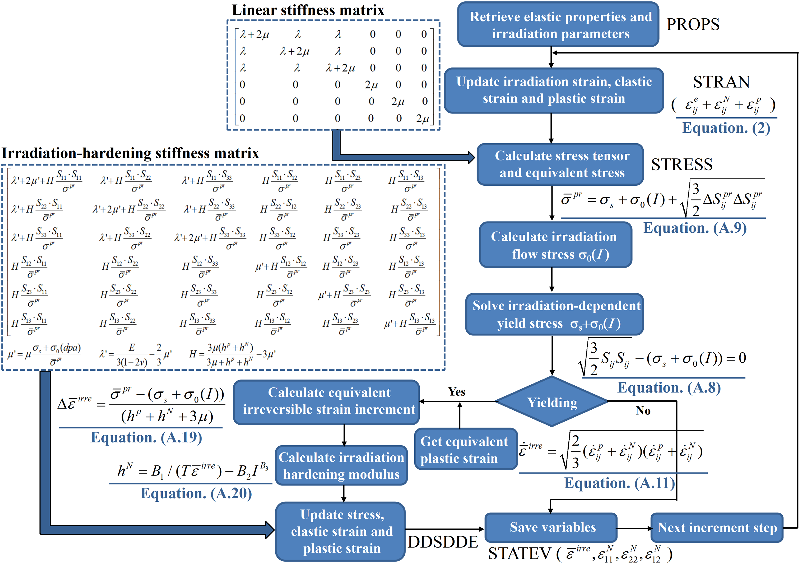
Numerical implementation flowchart of the phenomenological constitutive model.
The model was implemented in the finite element framework utilizing the incremental form. In ABAQUS/Standard, the stress tensor shown in Table 1 was calculated from an accumulative form across different deformation stages. The backward Euler method was used to integrate the rate equations, allowing the constitutive rate equations to be transformed into incremental equations. Then physical fields of every increment step can be calculated and transmitted to the next step. The computational scheme incorporates a numerically consistent tangent modulus, while second-order convergence is attained during the nonlinear iterative process. By accumulating the calculated stress states and strain states at each increment step, the physical fields of the entire geometric model can be determined.
The finite element implementation is based on the principle of virtual work:
Under the small deformation assumption, the strain–displacement relationship is given by:
After finite element discretization, the nonlinear equilibrium equations are obtained as:
The above nonlinear equations are solved using the Newton–Raphson iteration scheme. At the k-th iteration, the following linearized system is solved:
The above governing equations are solved by the finite element solver (ABAQUS/Standard). The user-defined material subroutine developed in this work provides the constitutive response at each integration point. Given the strain increment
Firstly, according to the constitutive relationship before yielding as described in Table 1, the linear elastic states in irradiated fcc metals can be determined using the user-defined material properties and the linear stiffness matrix.
Secondly, the current stress state is determined based on whether yielding has occurred. The equivalent stress 
The variation rate of dislocation density 
By substituting Equations (7) and (8) into the constitutive equations in Table 1, the irradiation-induced variation of macroscopic plasticity can be calculated. Note that the defect evolution in Equation (8) satisfies
Subsequently, the plastic hardening modulus is calculated and incorporated into the numerical calculations. As long as the equivalent stress exceeds the yield strength, all variables will be updated according to the constitutive relationship after yielding. Otherwise, the increment step will continue to follow the linear stage. Through calculating both the radiation-induced hardening coefficient and the increment of equivalent permanent deformation, the plastic strain tensor is obtained based upon the equivalent irreversible strain, the deviatoric stress tensor and the hardening modulus. The solution of stress field requires utilizing the stiffness matrix at different deformation stages. The consistent Jacobian (DDSDDE), namely the stiffness matrix, is defined as the partial derivative of the increment of the stress tensor with respect to the increment of the strain tensor. At the beginning of the iterative process, the initial tangent matrix is constructed according to the expressions valid at the onset of the load step. For later substeps, an updated matrix is derived from the revised constitutive relations to compute the stress tensor. At the same time, adjustments to the constitutive description are obtained by employing the stiffness matrix established at the conclusion of the preceding iteration. According to the constitutive model, the stiffness matrix was derived and represented in Figure 1. The stress tensor can be solved using the stiffness matrix and the calculated irreversible strain tensor.
In the present simulations, 4-node bilinear plane strain elements (CPE4) are used for the 2D plane strain models, and 8-node hexahedral reduced-integration elements (C3D8R) are used for the 3D validation model. Each node has 2 degrees of freedom for plane models and 3 degrees of freedom for the 3D model. A 2 × 2 Gaussian quadrature scheme is adopted for CPE4 elements, while reduced integration with hourglass control is used for C3D8R elements. The global convergence criterion is set to a force residual norm of 10−6.
Validation of the presented constitutive model
Two numerical examples were calculated to validate accuracy of the presented constitutive model. 304 stainless steel (304SS) and 316 stainless steel (316SS) are commonly used fcc metals in reactor components. These two materials are utilized as testing materials in this study. By comparing experimental stress–strain relationships (Ashrafi-Nik, 2006; Byun and Farrell, 2004; Evers et al., 2004; Monnet and Mai, 2019; Patra and McDowell, 2012; Spino et al., 2003) and the FEM results, accuracy of the presented constitutive model can be verified.
A three-dimensional displacement-controlled model was analyzed using the FEM using the numerically implemented constitutive model. Dimensions of the tested model are 10 mm, 100 mm, and 50 mm in the x, y, and z direction, respectively. The test model and the mesh result are depicted in Figure 2. Mesh convergence studies ensured that the results were independent of element dimensions. Using the developed user-defined subroutine, the model was simulated as the irradiated fcc metals to study mechanical behaviors under irradiation.
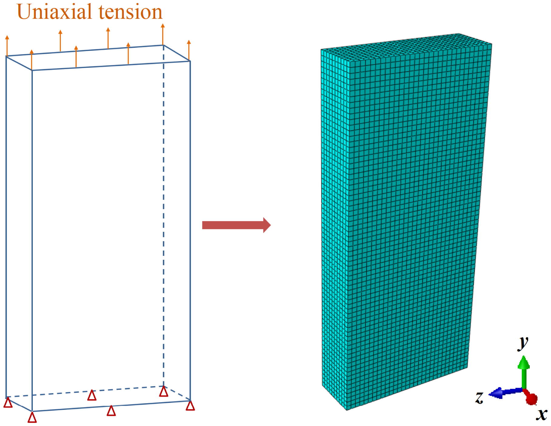
The geometric model and the mesh result for testing the presented constitutive model.
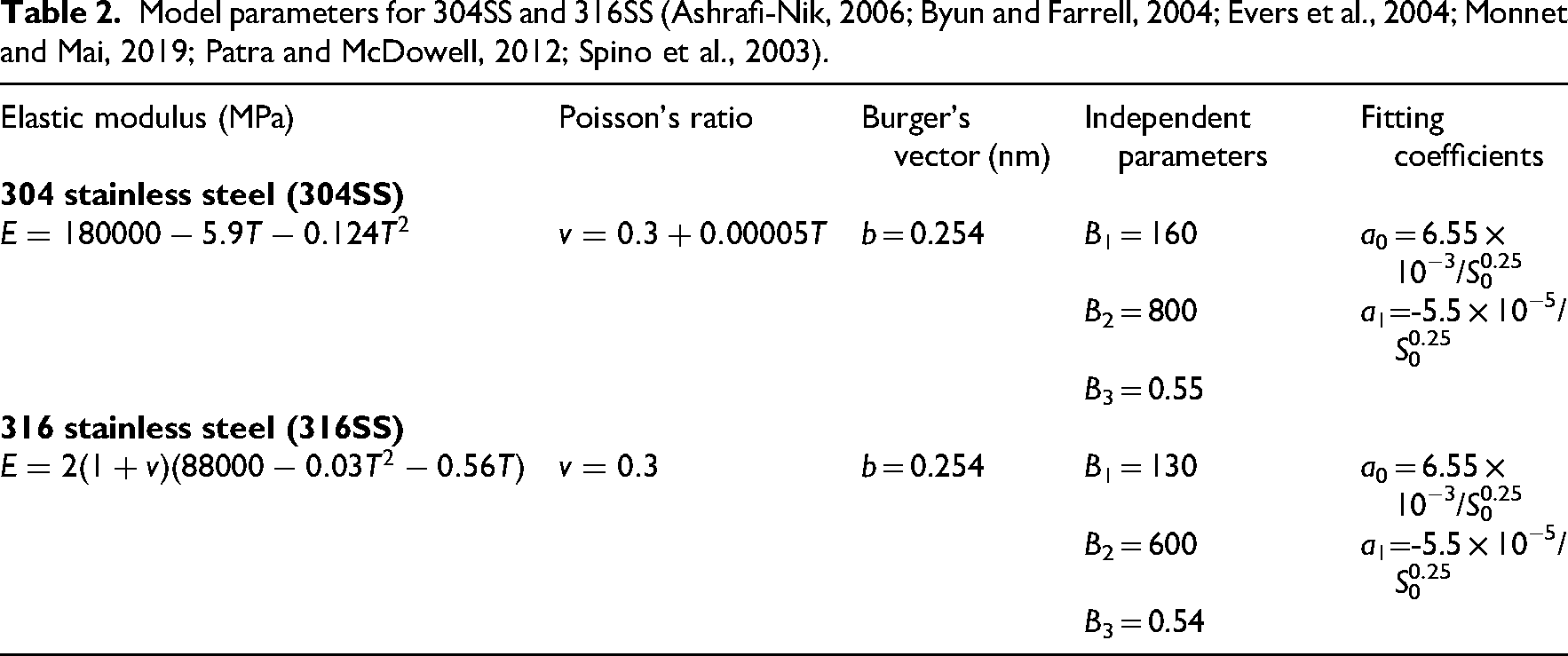
All material constants and irradiation parameters utilized in the simulation are detailed in Table 2. In addition, material constants of dislocations were determined to be kmul = 0.134 and kdyn = 329.5 (Evers et al., 2004). Taylor factor was set as ξ = 3.08 for 304SS and 316SS. The capture radius and average size of dislocation were taken as Rc = 8.5b and ld = 100b (Patra and McDowell, 2012), respectively. The typical distance that dislocations glide between adjacent obstacles, denoted as lg, was taken as 20 nm for 304SS and 316SS.
Model parameters for 304SS and 316SS (Ashrafi-Nik, 2006; Byun and Farrell, 2004; Evers et al., 2004; Monnet and Mai, 2019; Patra and McDowell, 2012; Spino et al., 2003).
According to numerical calculations, the mechanical responses obtained from the present constitutive formulation were validated against experimental measurements (Byun and Farrell, 2004; Maloy et al., 2001; Monnet and Mai, 2019), as presented in Figure 3. Experimental results were obtained by tensile tests of heat-treated subsize compact tension specimens. And simulation temperatures for all materials were identical with those in tests.
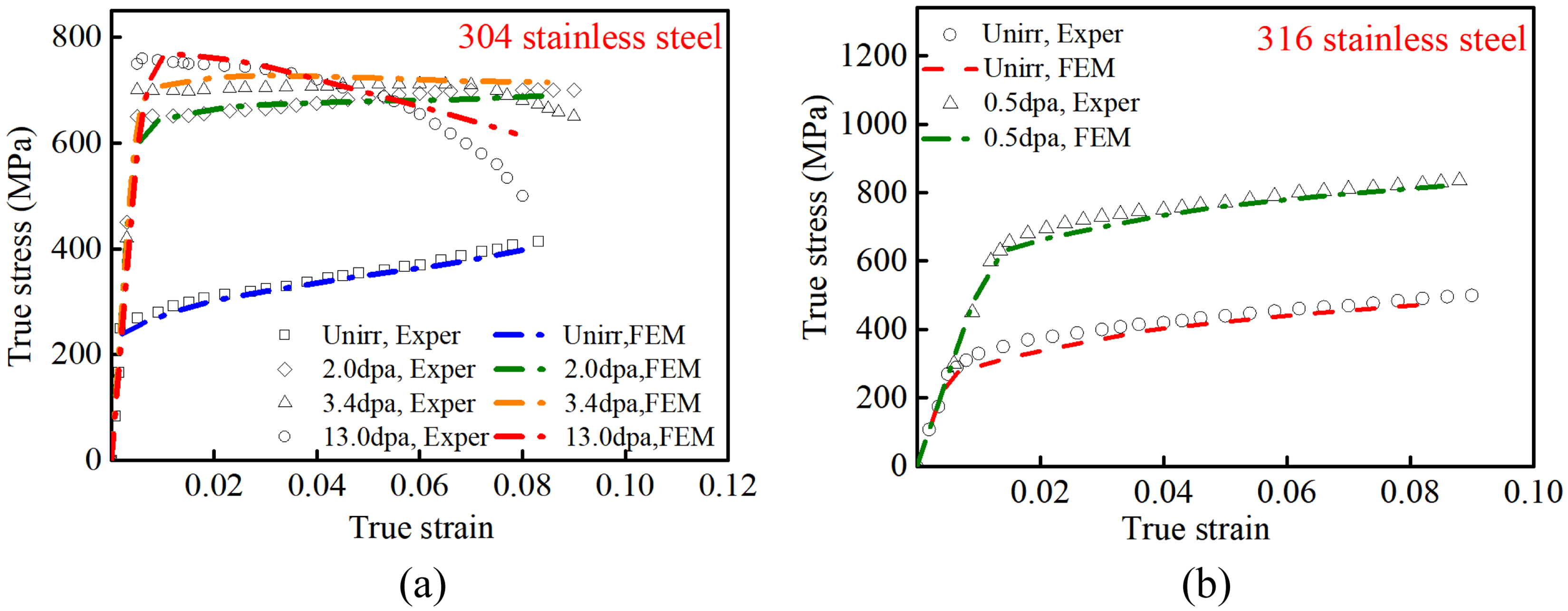
Comparisons of the experimental data (Maloy et al., 2001; Monnet and Mai, 2019; Byun and Farrell, 2004) and the predicted stress–strain curves for (a) 304SS and (b) 316SS.
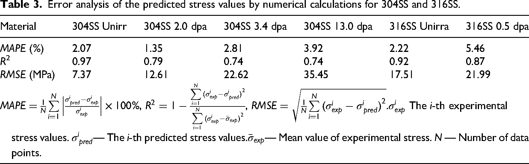
As shown in Figure 3, the constitutive curves obtained from FEM calculations closely match the measured results for both 304SS and 316SS across various irradiation dose levels. The developed constitutive model reproduces irradiation-dependent plastic deformations for various fcc metals across different doses. The accuracy of the numerical results in Figure 3 demonstrates the practical validity of the presented phenomenological model for different fcc metals. This advantage can be further assessed with additional irradiation data in the future. Accordingly, the developed constitutive model is validated to be feasible and accurate for characterizing constitutive relationships of irradiated fcc metals over a wide irradiation range. To quantitatively assess the model accuracy, the mean absolute percentage errors (MAPE), coefficient of determination (R2) and root mean square error (RMSE) between the predicted and experimental stress values are calculated over the plastic deformation stage, as depicted in Table 3.
Error analysis of the predicted stress values by numerical calculations for 304SS and 316SS.
The presented constitutive formulation accurately captures how irradiation influences both the initial yield threshold and the post-yield flow stress. On the one hand, the yield strengths of different materials increase with elevated irradiation doses (dpa), as demonstrated in Figure 3. On the other hand, the hardening modulus after yielding declines nonlinearly as the irradiation extent increases. The hardening modulus is represented by the slope of stress–strain curve beyond the yield strength. That value is hardly altered at the regime of low doses, as presented by data of 0.5 dpa in Figure 3(b). The slope of stress–strain curve for 0.5 dpa is almost the same as that of the unirradiated curve. But with irradiation doses increasing, the hardening modulus gradually decreases. The plastic stress after yielding declines evidently under strong irradiation. For instance, as illustrated by the data at 13.0 dpa in Figure 3(a), the plastic stress after yielding for the 304SS drops to less than the yield strength. The critical dose value for the hardening modulus altering is different for diverse materials. In the numerical implementation, the plastic stress declining under high doses is the direct consequence of the formalism in Equation (A.20), which provides the influences of irradiation doses, temperature and mechanical loading on the irradiation hardening modulus. As the effects of multi-scale irradiation behaviors are manifested at the component level, the phenomenological model is beneficial for conducting the cracking analysis.
Consequently, the proposed phenomenological constitutive model is validated to be accurate within the irradiation range considered in this study, which already encompasses the typical service dose interval for structural components in engineering practice. For special service conditions under ultra-high irradiation doses (e.g. lead–bismuth reactors and fast reactor core materials), the assumption of additive decomposition may become less accurate due to nonlinear coupling effects. Such very high irradiation doses or large plastic deformation will be addressed in future work. For the presented model, the typical plastic behaviors in irradiated fcc metals, including the increased yield strength and the declined plastic stress after yielding, can be reproduced macroscopically. By utilizing the developed phenomenological constitutive model, the relatively precise true stress–strain relationships for various materials exposed to a wide range of irradiation doses are determined for further investigation of cracking in irradiated fcc metals.
The effect of irradiation doses on the cracking behavior
The effect of irradiation doses on the plastic zone near the crack tip
Using the developed constitutive model, this work primarily investigates the effects of irradiation on the plastic region surrounding the crack tip and the energy release rate. The plastic zone near the crack tip is defined as the region where the equivalent plastic strain exceeds zero. It highlights the domain where the plastic deformation occurs. Through normalizing the region where the equivalent stress is less than the yield strength and emphasizing the contour plot of plastic stress, the plastic zones near the crack tips under different irradiation doses can be plotted.
Uniaxial tensile simulations of a central crack sheet model were conducted to explore the effects of irradiation on the plastic zone and the J-integral near the crack tip. The finite element model and the mesh result are presented in Figure 4. A plane-strain fracture specimen measuring h = 100 mm in length, w = 50 mm in width, and containing a centered notch of length a = 11 mm was analyzed utilizing the irradiation constitutive model. Desired parameters in the user-defined material subroutine utilized data of the 304SS in Table 2.
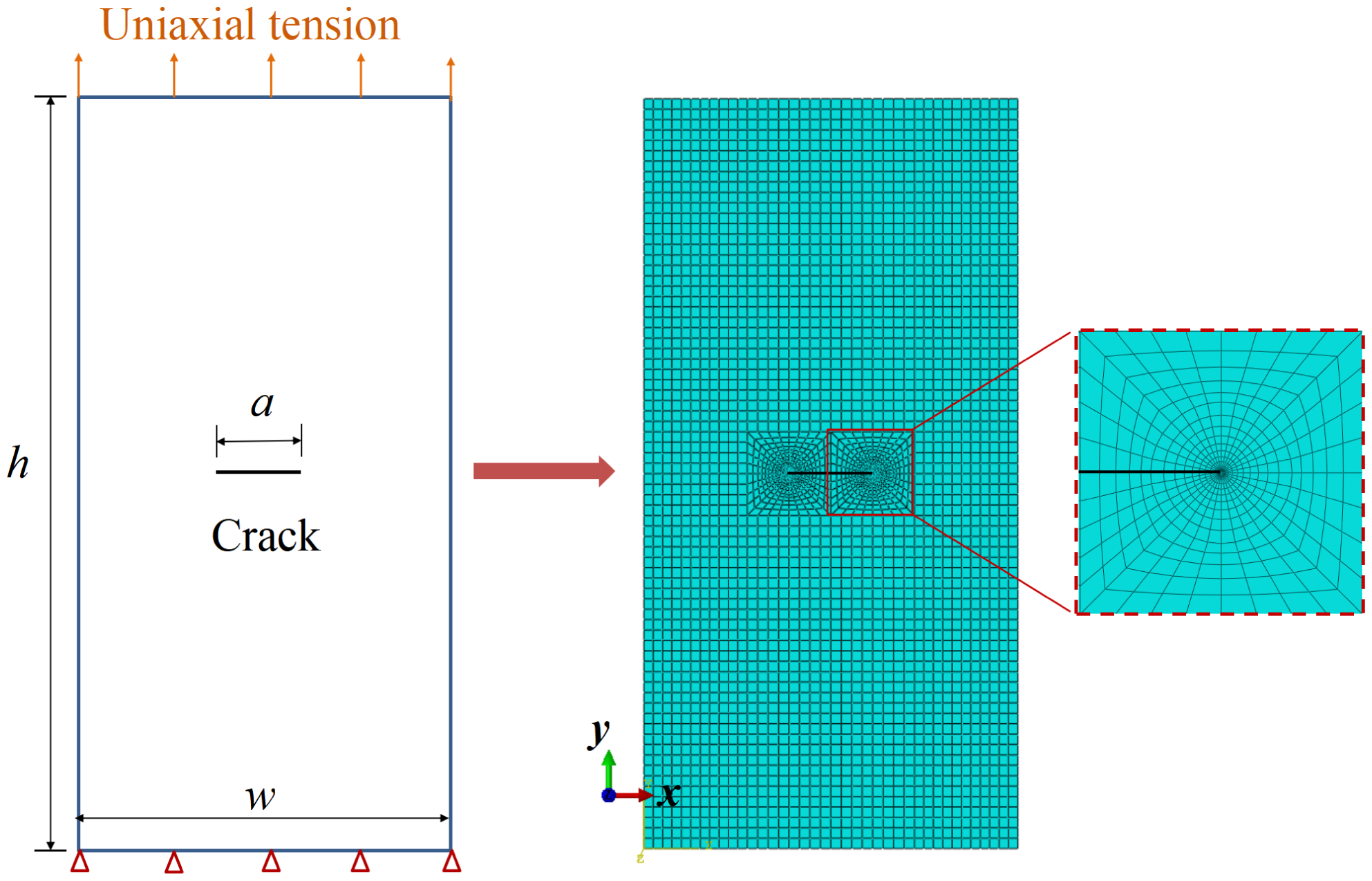
The finite element model and the mesh result for the central crack sheet subjected to the uniaxial tension.
In finite element models, a sharp crack is explicitly modeled using the seam crack function. To capture the
Variations of the Mises stress fields near the crack tip with irradiation doses are represented by the contour plots in Figure 5(a). All models were loaded under the applied displacement of Δh/h = 0.4%. The irradiation dose ranged from 1 dpa to 4 dpa. The simulation results reveal that irradiation causes the plastic stress at the crack tip to rise. The distribution of Mises stress around the crack becomes more pronounced as the irradiation level increases, with the peak Mises stress growing steadily under higher doses. Thus, exposure to radiation amplifies the stress concentration ahead of the crack tip in fcc metals.
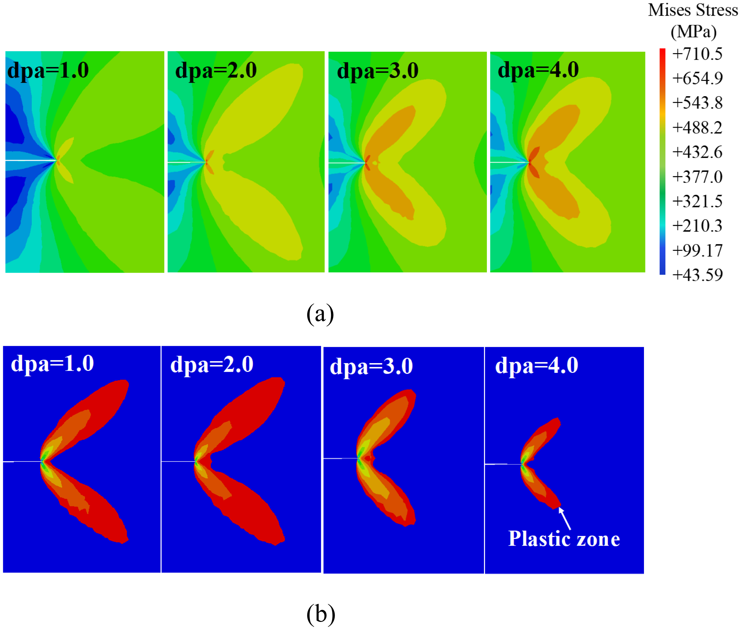
Variations of (a) the Mises stress field and (b) the corresponding plastic zone near the crack tip with irradiation doses (dpa). The plastic zone boundary is defined as the isoline where the equivalent plastic strain equals zero.
However, under the same external loading, the dimension of the plastic zone near the crack tip decreases as irradiation doses increase. Figure 5(b) presents the plastic zone near the crack tip corresponding to the Mises stress field under different doses. The boundary of the plastic zone is therefore the isoline where the equivalent plastic strain equals zero, that is, the elastic–plastic interface. For clarity, the dimension of the plastic zone near the crack tip was calculated. The irradiation effect on the plastic zone dimension is depicted in Figure 6. The dimension was normalized using the plastic zone size A0 at 1 dpa. As illustrated by the red data in Figure 6, the plastic zone near the crack tip decreases nonlinearly as irradiation doses increase.
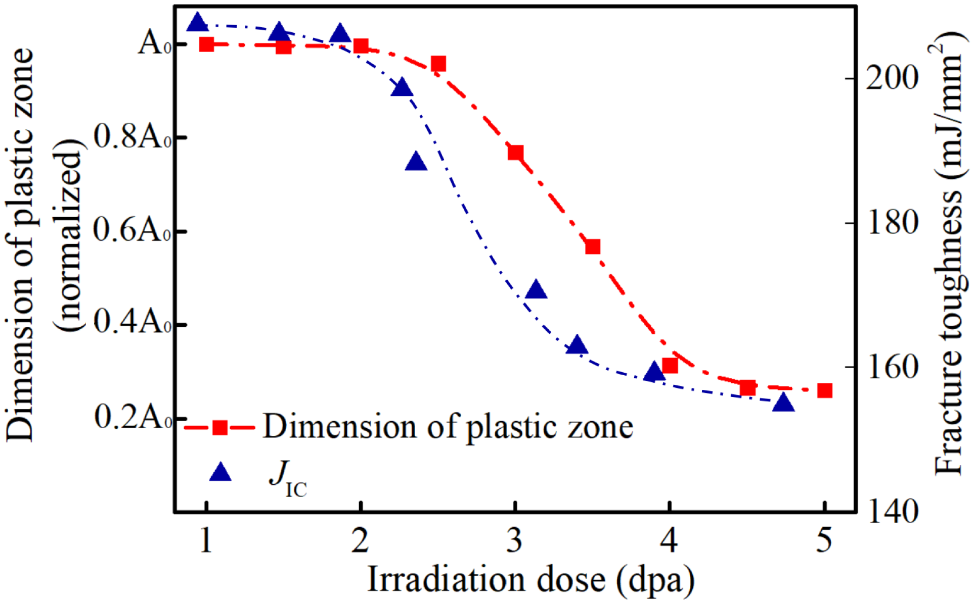
Comparison of the plastic zone dimension near the crack tip and the fracture toughness JIC (Maloy et al., 2001) under different irradiation doses (dpa). A0 is a normalized measurement area, representing the dimension of plastic zone under 1 dpa.
Simultaneously, the irradiation effect on fracture toughness measured experimentally is depicted as the blue data in Figure 6 (Maloy et al., 2001). The original fracture toughness data were obtained by testing the KIC of irradiated 304SS. This study transformed the KIC to JIC using the relationship of J = K2/E (Li et al., 2016). When the irradiation dose increases from 1 dpa to 4 dpa, the variation of fracture toughness is relatively consistent with the plastic zone near the crack tip. As the irradiation dose increases, both the plastic zone size at the crack tip and the fracture toughness exhibit a sigmoidal variation. When the irradiation dose increases from 1 dpa to 2 dpa, the crack-tip plastic zone size and fracture toughness remain almost unchanged. As the dose increases from 2 dpa to 3 dpa, the crack-tip plastic zone size decreases by approximately 54%, while the fracture toughness decreases by about 7%. When the dose further increases to 4 dpa, the crack-tip plastic zone size decreases by approximately 65%, and the fracture toughness drops to 78% of its value at 1 dpa. As the dose increases from 4 dpa to 5 dpa, the changes in mechanical properties become slower. The crack-tip plastic zone size decreases by about 5%, while the fracture toughness remains almost unchanged. It is recognized in Figure 6 that the irradiation effects on the plastic zone near the crack tip and the fracture toughness are positively correlated.
The irradiation effect on fracture toughness can be interpreted through the analysis of the plastic zone near the crack tip. As stated in Section “Validation of the presented constitutive model,” the plastic stress after yielding has been demonstrated to evidently decrease with increasing irradiation doses, while the yield strength increases monotonously. The degradation of fracture toughness in irradiated fcc metals results from both the irradiation-induced increase in yield strength and the drop in plastic stress. As the plastic zone emphasizes the region where the equivalent stress exceeds the yield strength, the evolution of plastic zone in irradiated fcc metals is determined by the combined consequence of the yield strength increasing and the plastic stress dropping. Thus the plastic zone near the crack tip can be utilized as a valuable metric representing the irradiation-induced fracture toughness degradation mechanism. Through calculating the evolution of the plastic zone near the crack tip, the fracture toughness degradation mechanism in irradiated fcc metals can be interpreted. Furthermore, based on the J-dominant criterion, the irradiation effect on the cracking behavior can be estimated by comparison of the fracture toughness and the crack tip J-integral.
The effect of irradiation doses on the J-integral near the crack tip
Furthermore, the J-integral was evaluated for various irradiation scenarios using the finite element environment. This fracture parameter characterizes the energy dissipated per unit crack extension. The center-cracked sheet shown in Figure 4 served as the computational model. It was calculated according to the conventional expression (Li et al., 2016):
The classical J-integral remains path-independent under the following conditions: (i) monotonic loading (no unloading), (ii) small deformation, and (iii) material behavior derivable from a potential function. For irradiated materials satisfying these conditions, the classical theory is a valid engineering tool. The numerical examples in this work all satisfy the classical assumptions. Integration contours were carefully chosen to fully enclose the plastic zone around the crack tip. However, at very high irradiation doses, irradiation-induced microstructural evolution may cause the material behavior to deviate from the classical assumptions, potentially affecting the path-independence of the J-integral. Under such strong irradiation-mechanical coupling conditions, the validity of the classical J-integral as a fracture parameter should be re-examined. Developing a modified J-integral formulation or adopting more rigorous fracture parameters will be the focus of future work.
Figure 7 plots the calculation results of the J-integral near the crack tip under different doses. The amount of irradiation ranges from 0 to 5 dpa. The influences of irradiation and mechanical loads are analyzed separately. Under displacement loads, the J-integrals of materials irradiated with different doses are depicted in Figure 7(a). It is noted that the present validation is limited to stress–strain curves due to the scarcity of experimental J-integral data for irradiated fcc metals containing cracks. Nevertheless, the capability of the proposed model for analyzing the cracking behavior of irradiated fcc metals can be indirectly supported by the agreement between the predicted and analytical J-integral for unirradiated materials, the accurate prediction of constitutive behavior, and the consistency with the irradiation dose-dependent evolution of fracture-related parameters.
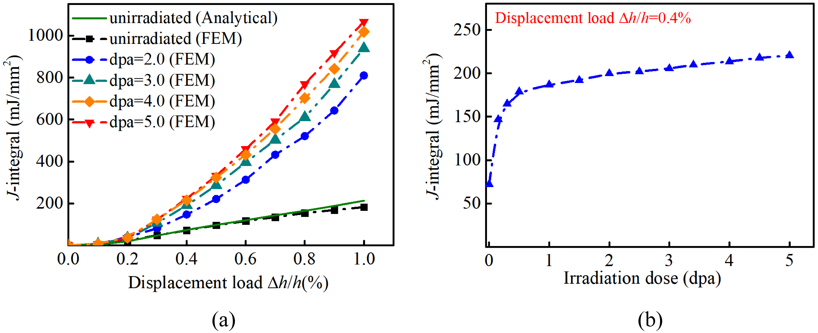
The effect of irradiation on the J-integral near the crack tip. (a) Variation of the J-integral with mechanical deformations under different doses; (b) Variation of the J-integral with irradiation doses under the displacement load of 0.4%.
For the unirradiated materials, it is demonstrated in Figure 7(a) that the J-integral calculated by FEM agrees well with the classical analytical results using Equation (9). This good agreement confirms the correctness of the current numerical procedure. Therefore, the proposed constitutive description is capable of predicting the onset and growth of cracks in irradiated fcc metals.
Figure 7(a) reveals that the J-integral grows as the applied tensile deformation increases, although the rate of this growth depends on the irradiation level. Taking the 0.6% displacement load as an example, as the irradiation dose increases from 0 dpa to 5 dpa, the J-integral increases from 116.28 mJ/mm2 to 459.12 mJ/mm2, an increase of approximately 295%. At a higher load level (1.0% displacement load), the J-integral further increases to 1066.61 mJ/mm2, corresponding to an increase of approximately 485% relative to the unirradiated case. It is also observed that under low mechanical loads (<0.2%), the J-integral remains almost unchanged across different irradiation doses. In contrast, in the higher dose range (2–5 dpa), the J-integral exhibits a nearly linear increasing trend with respect to the applied load.
It is recognized in Figure 7(a) that irradiation enhances the J-integral near the crack tip under the identical external loading. Physically speaking, the J-integral manifests the energy release rate at crack tip. This invariant integral in fracture mechanics corresponds to the amount of potential energy liberated during crack advance. Consequently, the impetus for crack extension becomes larger in irradiated fcc metals, though its enhancement with rising irradiation dose follows a nonlinear trend.
Furthermore, the irradiation effect on the driving force of crack propagation is analyzed at length. Under the displacement load of 0.4%, the variation of J-integral with doses is depicted in Figure 7(b). It is observed that the J-integral increases with the raised magnitude of irradiation doses, while the variation rate decreases as the dose increases. As the irradiation dose increases from 0 dpa to 0.15 dpa, the J-integral increases rapidly from 72.15 mJ/mm2 to 146.89 mJ/mm2, an increase of approximately 147%. Subsequently, as the dose increases from 0.15 dpa to 0.5 dpa, the J-integral increases to 178.92 mJ/mm2, corresponding to an increase of approximately 17%. This indicates that in the very low dose range (< 0.1 dpa), the J-integral is extremely sensitive to dose variations. When the irradiation dose further increases beyond 1 dpa, the J-integral exhibits a nearly linear increase with increasing irradiation dose.
In the low-dose range, the J-integral rose substantially. Its rate of increase gradually diminished as the radiation dose grew larger. The observed changes in material behavior stem primarily from irradiation-induced microstructural evolution. Nevertheless, experimental data indicate that fracture toughness deteriorates under higher radiation exposure (Maloy et al., 2001). Multiple studies have indicated that, under small-scale yielding conditions, the J-integral can effectively characterize fracture behavior in metallic materials (Cherepanov, 1967; Li et al., 2016; Rice, 1968). According to the J-dominant criterion, crack extension begins once the computed J-integral attains the material's fracture resistance. Thus, it is concluded that irradiation accelerates cracking behaviors in fcc metals.
It is noted that the increase in J-integral with irradiation dose does not contradict the observed reduction of the plastic zone near the crack tip. The J-integral measures the energy release rate, which comprises both elastic and plastic contributions. Irradiation raises the yield strength, allowing higher elastic stress concentration at the crack tip. Consequently, although the plastically deformed region shrinks, the elastic energy stored per unit volume increases, leading to a net increase in the total energy release rate. This is a characteristic behavior of irradiation-induced embrittlement.
In operating reactors, structural components at different locations are exposed to varying extents of irradiation doses. Metallic materials that are closer to the nuclear fuels are irradiated by stronger neutron irradiation. Due to the complex effects of irradiation on the mechanical properties, it is significant to determine the cracking conditions for the safety of in-pile metallic materials. The presented method in this work can estimate the driving force of crack propagation under different doses. Then the safety of different structural components can be assessed during service period according to the J-dominant criterion.
Based on the developed constitutive model in this work, the J-integral near the crack tip in irradiated fcc metals can be numerically solved. The J-dominant criterion can be utilized for estimating the cracking behaviors of structural components fabricated by fcc metals in reactors. In next section, the presented numerical method will be utilized to analyze the cracking of fcc metal matrix in the dispersion nuclear fuel meat based on the J-dominant criterion.
Cracking analysis of an in-pile component
As an application illustration, the proposed model was applied to study matrix fracture within a dispersion-type nuclear fuel element. As illustrated in Figure 8, this fuel configuration resembles a particle-reinforced composite in terms of its structural layout. Through embedding ceramic fuel particles in a metallic binder, such fuel designs offer numerous benefits over traditional fuel pellets (Raftery et al., 2020), such as fuel utilization, safety, and other effective properties. Fcc metals, such as 304SS, are commonly used as the metal matrix. The predominant cracking mode of dispersion meat is that the running-through crack in the ceramic fuel propagates into the metal matrix (Long et al., 2014).
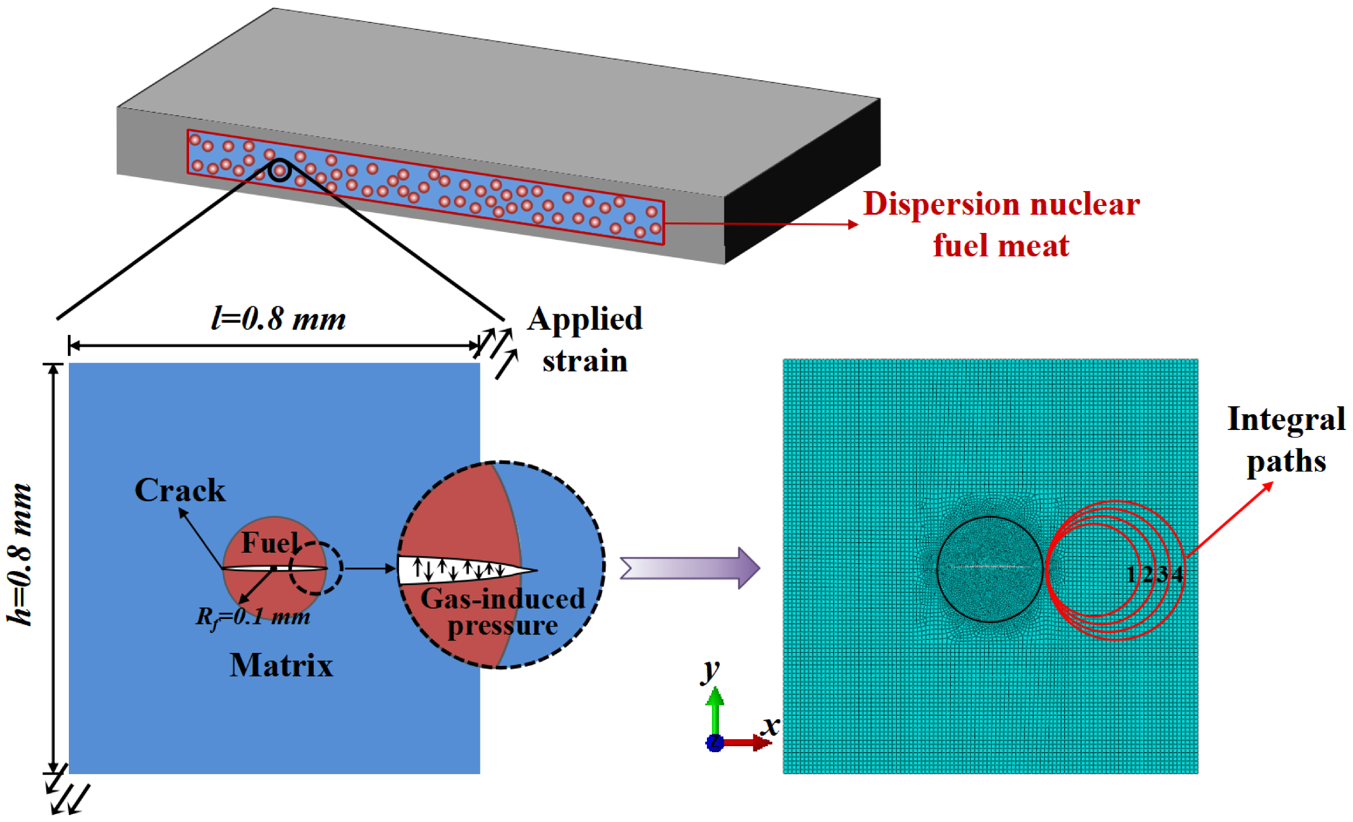
The individual fuel particle model incorporating with the running-through crack and the mesh result in FEM.
As shown in Figure 8, an individual fuel particle model incorporating a running-through crack was extracted from the dispersion fuel meat. Based on the presented constitutive model, the crack-tip J-integral values were computed numerically for various irradiation dose levels. These results were then employed, based on the energy balance approach, to examine how irradiation influences matrix fracture within the dispersion nuclear fuel.
The individual fuel particle model has dimensions of 0.8 mm × 0.8 mm (i.e. 0.8 mm in both the x and y directions). These dimensions are sufficiently large to eliminate the size effect of fuel particles on the simulation results. The fuel particle was set as UO2, while the matrix utilized the irradiated 304SS implemented by the user-defined material subroutine. The elastic modulus of UO2 ceramic is a function of temperature and burnup, represented as (Spino et al., 2003):
Within the operating reactor, large amounts of gaseous fission products are generated in dispersion fuel particles. The onset of through crack propagating is driven by the internal pressure induced by fission gases. The pressure can be expressed as (Long et al., 2014):
This application example concentrates on the mode I cracking of a running-through crack in the dispersion nuclear fuel meat. The formalism in Equation (9) actually represents the remote invariant integral computed under the remote loading at infinity (Li and Lv, 2017). Hence, in order to analyze the driving force of mode I cracking, the fuel particle model incorporating with a running-through crack was loaded under the remote applied strain, as shown in Figure 8. The crack surfaces were subjected to a gas-induced pressure of 87 MPa, which controls their deformation. In this way, the mode I cracking of the dispersion fuel meat can be quantitatively analyzed. Additionally, to improve the computational accuracy and convergence, the mesh was refined at the crack tip. The finite element model and mesh result are presented in Figure 8.
The irradiation dose ranged from 1 dpa to 4 dpa. According to the FEM results, the J-integral was calculated by performing the post-processing script. To ensure the validity of Equation (9), the selection of the integral path requires that (i) the fuel phase should not be included in the integral domain; (ii) the crack tip must be included; and (iii) the plastic zone near the crack tip should be bypassed to improve convergence. Therefore, through writing the post-processing calculation script, this study implements the eccentric circle integral path as demonstrated in Figure 8.
Figure 9(a) displays the von Mises stress distributions adjacent to the penetrating crack tip within the matrix for various radiation exposure levels. The results indicate that the peak von Mises stress grows as the radiation level intensifies. Within the dispersion nuclear fuel, the stress concentration is enhanced by irradiation. Nevertheless, the corresponding plastic zone decreases as the irradiation extent increases, as shown in Figure 9(b). That is attributed to the combined result of yield strength increasing and plastic stress decreasing in irradiated matrix.
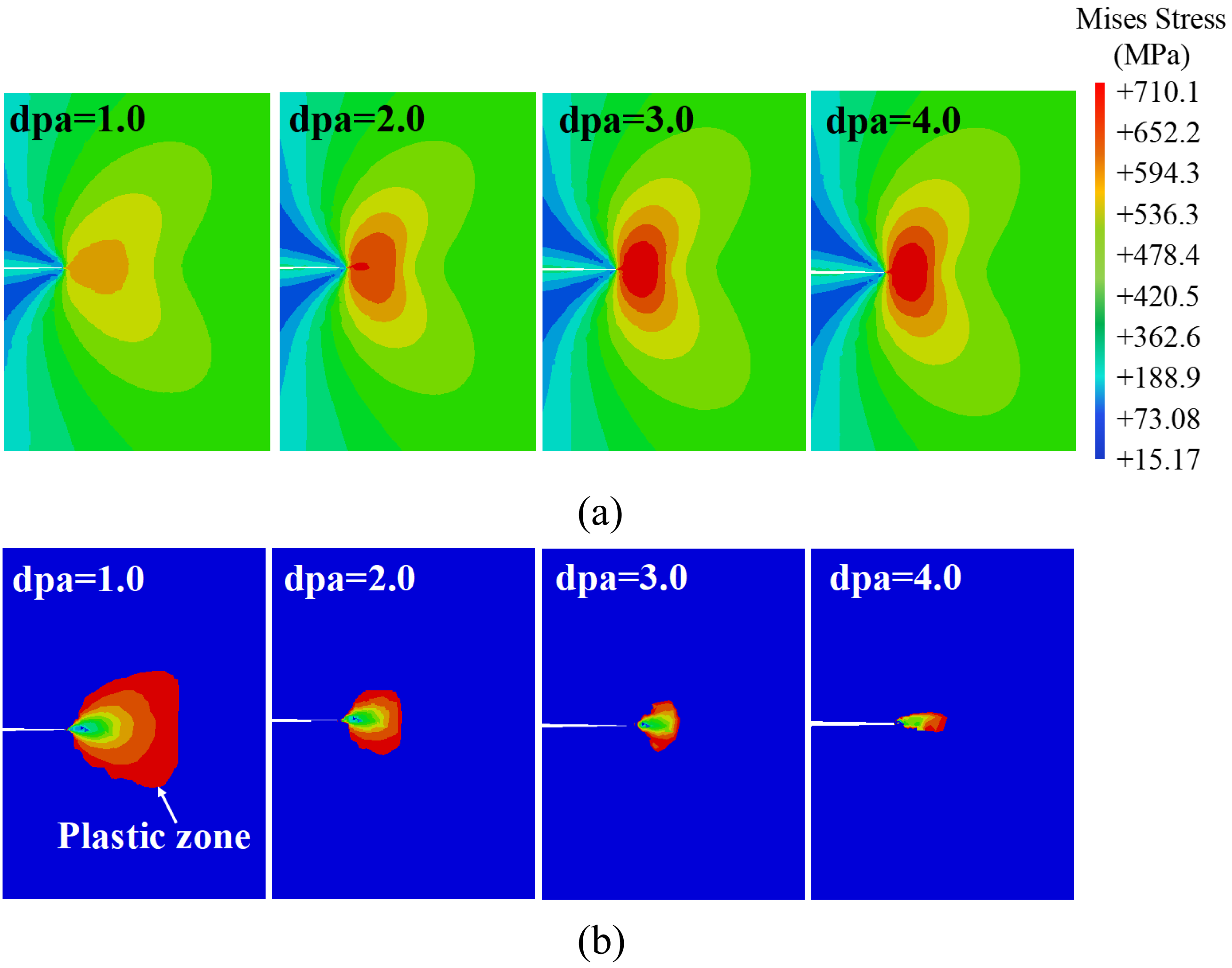
Variations of (a) the Mises stress field and (b) the corresponding plastic zone near the through crack tip with irradiation doses (dpa). The plastic zone boundary is defined as the isoline where the equivalent plastic strain equals zero.
Using the distributions of stress, strain, and strain energy density in the vicinity of the penetrating crack tip, J-integrals under different irradiation conditions were solved, as depicted in Figure 10. The J-integral increases as the irradiation extent increases. But a nonlinear correlation between the J-integral and irradiation doses has been found. The driving force of cracking increases nonlinearly with the magnitude of irradiation doses. Apart from that, the fracture toughness JIC declines with the irradiation dose in experiments (Maloy et al., 2001), as represented in Figure 10. When the J-integral reaches the fracture toughness JIC, the running-through crack propagates into the matrix (Li et al., 2016). Therefore, according to the relevance of fracture toughness and irradiation plotted in Figure 10, the J-integral will reach the fracture toughness easier at the regime of high level of irradiation. With the same far-field applied strain, increasing the irradiation doses will exacerbate the cracking behavior in fcc metal matrix.
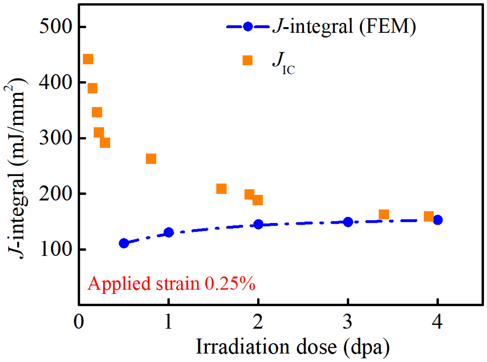
Variations of the J-integral near the crack tip and the fracture toughness JIC (Maloy et al., 2001) with irradiation doses (dpa).
Conclusions
In this study, by calculating the fracture parameter (J-integral) under different neutron doses, the cracking behavior for irradiated fcc metals was investigated using a phenomenological constitutive model. The degradation of fracture toughness in irradiated fcc metals is found to be correlated with the irradiation-induced evolution of the plastic zone near the crack tip. The main conclusions are as follows:
A phenomenological constitutive model of irradiated fcc metals has been derived and numerically implemented in the framework of FEM. Comparisons between simulated results and experimental data validate the accuracy and feasibility of the presented model across a wide irradiation range, even in the high-dose regime. The plastic zone near the crack tip in irradiated fcc metals nonlinearly decreases as the irradiation dose increases. The consistent influence of irradiation on the plastic zone and fracture toughness enhances the interpretability of the irradiation-induced fracture toughness degradation mechanism. Compared with unirradiated fcc metals, the energy release rate rises logarithmically with increasing irradiation dose. The presented numerical method can be utilized to calculate the J-integral and to further evaluate the cracking in irradiated fcc metals based on the energy criterion.
From an engineering perspective, the proposed model enables a quantitative estimate of the critical irradiation dose for crack propagation through the intersection of the J-integral and fracture toughness curves, demonstrating its potential for establishing safety limits in reactor structural integrity assessments. The same methodology can be applied to other fcc metals and loading conditions by calibrating the model parameters accordingly.
Footnotes
Acknowledgments
The authors are grateful for the fundamental research funds for the central universities (xzy012025038) and the funding from the China Scholarship Council. The computation has made use of the High Performance Computing (HPC) platform of Xi’an Jiaotong University.

Author contributions
Yingxuan Dong did conceptualization, methodology, and writing-original draft; Qun Li performed writing-review and editing.
Funding
The authors disclosed the conflicts of interest with respect to the research, authorship, and/or publication of this article: This work was supported by the National Natural Science Foundation of China (12502095) and the Natural Science Foundation of Shaanxi Province (2025JC-YBQN-071).
Declaration of conflicting interests
The authors declared no potential conflicts of interest with respect to the research, authorship, and/or publication of this article.
Data availability statement
The data used in this study will be made available upon request to the corresponding authors.
Appendix A: Derivation of the constitutive model
Before yielding, the stress linearly increases with the elastic strain, satisfying the Hooke's law, that is,
The plastic strain component does not exist before yielding. According to the relation in Equation (2), the stress tensor
Displaced atoms have been found to be the primary damage form in irradiated materials exposed to high-energy neutrons (Monnet and Mai, 2019). Generally, displacement per atom (dpa) is utilized to qualitatively characterize the influence of irradiation on material structures (Arsenlis et al., 2004; Gussev et al., 2012; Krishna et al., 2010).
The contribution of neuron irradiation to the irreversible strain term, referred to as
By substituting Equation (A.3) into Equation (A.2), the constitutive equation before yielding is modified as:
According to the incremental theory of plasticity (Zhou, 2010), the stress tensor in the plastic stage after yielding is calculated based on the increment of equivalent plastic strain
By substituting Equation (A.1) into Equation (A.6), the increment of deviatoric stress tensor is represented taking the form of:
When the equivalent stress reaches to the yield strength, the plastic behavior occurs. As for irradiated materials, the irradiation-induced flow stress
It is observed in Equation (A.8) that the irradiation flow stress induces the increased yield strength, which is consistent with macroscopic irradiation behaviors (Boyne et al., 2013). Since the real stress tensor and the equivalent stress in the plastic stage have not been solved yet, a predicted equivalent stress based upon the elastic behavior is employed for theoretical derivations. Subsequently, the stress tensor and the irreversible strain tensor will be modified by introducing the hardening modulus. The predicted equivalent stress should be equal to the sum of yield stress and the increment of predicted equivalent stress
By replacing the increment of elastic strain in Equation (A.7) with the increment of total strain, the increment of predicted deviatoric stress tensor is determined as:
According to the incremental theory of plasticity (Zhou, 2010), the equivalent plastic strain represents the invariant of plastic strain tensor. In irradiated metallic materials, the irreversible strain of plastic stage is composed by the irradiation strain
Combining the yield stress subjected to irradiation in Equations (A.4) and (A.11), the irreversible strain rate in the plastic stage, that is, the sum of plastic strain rate and neutron-irradiation strain rate, is represented as:
When the predicted equivalent stress reaches the yield strength, the variation rate of stress with strain is equal to the sum of plastic hardening modulus
According to Equation (A.12), the increment of irreversible strain tensor is represented in the following form:
By substituting Equations (A.7) and (A.13) into Equation (A.14), the increment of irreversible strain is modified as:
According to Equation (2), the increment of elastic strain is equal to the total strain increment minus the plastic strain increment and the neutron-irradiation strain increment, namely
After some manipulations, the expression in Equation (A.16) is rearranged as follows:
Through introducing the increment of predicted deviatoric stress tensor of Equation (A.9), the expression in Equation (A.17) is modified as:
By substituting Equation (A.9) and the incremental formation of Equation (A.11) into Equation (A.14), after algebraic operations, the increment of irradiation-dependent equivalent irreversible strain is depicted by:
The plastic hardening modulus
Thereby, the increment of equivalent irreversible strain is modified by substituting Equation (A.20) in Equation (A.19), that is,
Furthermore, by substituting the increment form of Equations (A.3) and (A.21) into Equation (A.14), after some manipulation, the plastic strain tensor is depicted by: