
Abstract
One key to efficient and effective reuse in product-developing companies is platform-based design. Future platforms need to more efficiently deal with: concurrency, information-rich designs and fast realization of design derivates. This calls for new ways to describe platform-based designs. The configurable component framework is intended to support concurrent, complex, and variant-rich system design considering the complete product life cycle. This article presents case studies where an extended function-means model, acting as a design rationale, is incorporated into the configurable component concept. This includes an adaptation to handle design bandwidth, a more transparent and explicit constraint handling, and the composition of a system design rationale based on multiple function-means models. This approach enables the description of complex, encapsulated configurable systems composed using multiple (sub) systems and supports concurrent engineering in a supply chain.
Keywords
Introduction
One of the main drivers for platform-based development and manufacturing is the possibility to combine customization with economies of scale. The reuse of common resources in multiple customized design variants is one way of achieving this combination. When implemented, it is often referred to as carryover or commonality. Using one part in multiple products opens up for economy of scale in production. In other words, the reuse of parts promotes efficient manufacturing.
The possibility to carryover a number of unchanged parts, from a set of quality-assured product parts (a physical or traditional platform) to another design context is influenced by the desired design differentiation. A relatively small design differentiation may lead to a relatively large number of parts having to be modified. Consequently, the economic benefits in manufacturing may be significantly reduced or lost.
However, the reuse of design information promotes efficient and effective product development. Claesson (2006) presented a product description that supports reuse on a higher level of abstraction (a more abstract type of platform definition) to achieve the economy of scale within product development. In this article, problems identified in industrial case studies (as well as problems discussed in literature) have been addressed by proposing a more abstract approach to describing configurable design platforms. This approach is based on systems theory principles (e.g. Hitchins, 2003) and design theory (Andreasen, 1998; Hubka, 1997).
A platform formed in this way consists of design solutions (DSs) in various degrees of granularity, from overall concepts all the way to very detailed solutions, while being abstract. Physical parts are not primarily part of the platform but more a consequence of the abstract content.
Limitations using platform-based development
Researchers who have recognized the potential advantages of platform-based approaches have described and proposed different frameworks, methods, and mathematical tools to define and make use of such approaches in different industrial settings (Jose and Tollenaere, 2005; Simpson, 2004; Simpson et al., 2006). One advantage already mentioned and closely related to standardization and modularization is the increased reuse of resources aimed at economies of scale. A number of publications (e.g. Baldwin and Clark, 2000; Ericsson and Erixon, 1999) discuss different techniques for standardization and modularization in this context.
Platform implementation strategies to enhance economy of scale have been described, for example, by Simpson et al. (2006). A well-known industrial example reported in the literature is from Black and Decker (Meyer and Lehnerd, 1997; Simpson, 1998). Another industrial example, described by, for example, Prencipe (1998), is from Rolls Royce.
The content of the platform and how this content is developed and described are crucial for the simultaneous optimization of both reuse and design variety. A platform based on parts already designed has severe shortcomings regarding flexibility. More abstract and easily configurable platform descriptions have therefore been proposed. Van Veen (1991) proposed a generic bill-of-material (BOM) to provide the possibilities for the description of large varieties of product types and structures. The idea is to define product data on a level of sets of product types, rather than defining individual product types. Erens (1996) applied and explored this concept further when developing product families and synthesizing product variants. Gedell (2011) generalizes the definition further and also includes a life cycle perspective by the following definition: “A platform is a set of resources that contains the design solutions that will reduce the total design effort without limiting the identified and estimated derivate designs.”
Reuse is more than a matter of maximizing the degree of commonality. Too much commonality threatens the products’ differentiation within a product offer. With platform development support as a goal, it is important that product architectures can provide the means of identifying and defining how variability (and, with it, product distinction) is achieved (Berglund and Claesson, 2005).
Reuse can benefit from product descriptions that are information rich, that is, descriptions that contain additional explicit information besides the resulting design (McKerlie and MacLean, 1994). With information describing the reasoning behind the design and issues considered (in this article referred to as “why-information”), it is more likely that the design can be used and reused in accordance with what it was designed for.
The “why-information” that includes the design intent contributes with an understanding of how to modify the design without accidentally losing desired behavior and, more fundamentally, how to dare to make any changes at all, instead of having to remake the complete design. Another use is to support application in multiple contexts (i.e. use in another product than the one primarily intended). These uses are independent regardless of whether they occur simultaneously or sequentially.
Research approach
Research questions
The aim of the research presented in this article is to incorporate “why-information” in the product description, as an extension to the existing configurable component modeling framework. The idea is to adopt function-means (F-M) models to fulfill this purpose. According to design theory (Hubka, 1997) an F-M tree is a hierarchical model of one particular system decomposed into subordinate subsystems. According to Claesson (2006), a configurable component is an autonomous configurable system model of encapsulated combined systems. This difference in scope needs to be overcome before the F-M model can be fully utilized within the configurable component framework.
The research questions formulated to address these issues are as follows:
How could F-M trees be used as carriers of “why-information” within product platforms with platform elements defined by configurable components?
How could configurable components carrying “why-information” support platform design reasoning, and thereby designing?
Research methodology
The research in this article has mainly taken a constructivistic approach. Theory-based solutions are proposed to the identified problems and needs. Data models are used to illustrate key modeling aspects. Those models define what information can be handled and how this information is structured. In that sense, they are strongly prescriptive. However, the approach has been to define a data model with significant freedom and opportunities and not to define the process of how it should be used.
The conducted research includes aspects of action research within industrial settings. The findings and proposals have been used in cooperative projects within industry with two goals in mind: to verify and validate the configurable component concept model with its design rationale (DR) and to improve the companies’ understanding of their own products.
The research approach in this work is based on the method proposed by Jørgensen (1992). Following the approach proposed by Jørgensen (1992), the method’s dual starting points in this work are (a) a problem base that is found in cooperation with the industrial partners and (b) a theoretical foundation based on systems theory principles and design theory.
The research presented here focuses on what information is handled during product platform development and how that information should describe a “reality” represented by models. Besides delivering scientific contributions, there is also an explicit goal to deliver results relevant to industry. Such relevance is met if it is possible to implement parts of the proposed models in a computer-based software application. Duffy and Andreasen (1995) have used three different modeling steps to illustrate this. In order to describe Reality, they claim that Phenomena models, Information models, and Computer models/tools are needed. To be meaningful and to support the design work, all models are to represent reality while gradually increasing their level of detail, as well as the level of concretization. A phenomenon model describes basic constructs identified when observing and analyzing reality. The phenomenon model can be further refined, or detailed, into an information model where each piece of information is structured using, for example, classes and attributes. Such a model can then be implemented in software.
The case studies presented are handled by using a software tool. The research focus is on phenomena and information models, and the software tool is just used to verify the models as well as to handle the case studies’ information content. Consequently, the software implementation is just briefly mentioned.
Studying real-life industrial examples
The real-life industrial examples are taken from the automotive industry. A subset of a car is used to illustrate the proposed methodology. The examples are focused on how to describe the design’s depth rather than its width, in order to illustrate how a system is formed by subsystems, which in turn are formed by subsystems and so on. More precisely, the example includes front seats, delimited to seat heating, which is further delimited to seat heat element, and finally the heating wire. This approach will include a number of company boundaries, thereby visualizing the ability of the methods to support.
Included in the example is support for various product life cycle phases, illustrated as follows:
The design phase, when the design and its description is created;
During production, when the description is used as a source for logistic operations.
Frame of reference
This chapter introduces the two main elements in the theory base of this article, namely, systems theory in general and the configurable component framework, which has a focus on applied modeling of systems.
Systems theory
Systems theory is a theory designed to study unified whole systems. It has some key features: its ability to represent anything of interest, so-called systems, and the fact that each system is a whole that is more than the sum of its parts.
An organism is an example of an entity where the whole is more than the sum of its parts. More specifically speaking, the behavior of a system depends on its subsystems and their relationships. This additional contribution, the so-called emergent properties (Checkland, 1981), cannot be attributed to any specific part of the system. Rather, they emerge only when the system as a whole is considered. Hitchins (2003) expresses this clearly when he states: “The properties, capabilities, and behaviors of a system derive from its parts, from interactions between those parts, and from interactions with other systems.”
A key factor in successfully handling complex systems is to sometimes deal with a limited number of a system’s parts at a time, instead of with the complete system. Decomposition is a way of limiting the task; however, it has its own drawbacks. Hitchins (2003) describes how decomposition will make the parts lose their interactions, thereby losing their context. Elaboration and encapsulation, however, look at the parts in situ and in context, thus maintaining their interactions. In Figure 1, it is illustrated how encapsulation can be compared to placing containers around sets of entities, and the perceived complexity of the system is reduced when unnecessary details are hidden, whereas elaboration can be compared with magnifying glasses, where more details become visible when magnification is increased.
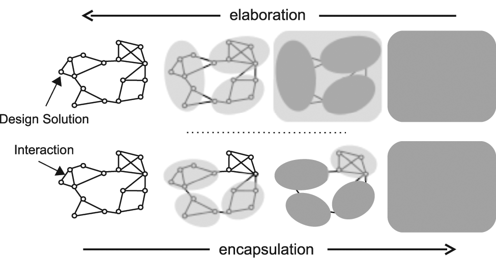
Two alternative elaborations and encapsulations.
The configurable component concept
The configurable component concept is a means of representing systems and their subsystems using a generic building block, the configurable component (Claesson, 2006). The original purpose of the concept is to handle data, information and knowledge sharing, as well as managing the conflict between commonality and reuse, while having the ability to represent variant-rich and complex products and, more generally, entire product platforms.
A configurable component represents a system, which can be elaborated and represented by a set of subsystems. In other words, the initial system is composed of a number of subsystems, which in their turn can be composed of others and so on. The model can support a decentralized setup where a designer is responsible for his/her level of granularity of the design.
A configurable component may be referred to by multiple compositions. Such references may cross product, as well as company boundaries. This requires that each configurable component should be as self-contained as possible. It also requires that parameters that describe variability should be expressed in a terminology relevant for the configurable component itself. A number of successive compositions can be perceived as a structure. For such a structure to exist, there must be a method capable of traversing a number of configurable components and presenting them as a structure. Such a traverse may start with any configurable component.
The configurable component has some constructs that can be regarded as basic—encapsulation, DS, variability, and composition.
Encapsulation will conceal the internal structure of the configurable component from the outside environment. Access is gained through interfaces, which make selected parts of the internal content available.
The DSs are the elements within a configurable component that describes the design. A DS can represent anything from an overall concept to the smallest detail.
Variability, the ability to represent a number of similar designs as one configurable component, is achieved by parameters. A specific variant, a configuration, is achieved by giving values to the parameters of the configurable component.
Composition is a feature in systems design where a system has the ability to compose itself using other systems to fulfill its purpose. Because both the parent system and its composition elements (CEs) (i.e. used systems) may be configurable, methods are needed to select the correct configuration of the used systems depending on the parent’s configuration.
Encapsulation is an enabler for decoupled design work, as the internal structure may be refined without affecting the outside. The various actors who together create a complete design by contributing with subdesigns can refine their designs with a reduced risk for locking or being locked up by other designs that are depending on their design. The designs’ interdependencies are however not neglected but represented by interactions via interfaces, with the intention to be stable over time. With these mechanisms in place, designing can be made concurrently, that is, Concurrent Engineering. Gedell and Michaelis (2011) applied the configurable component framework to describe concurrency between product development and manufacturing preparations. In this article, the framework will be applied for concurrent engineering between multiple actors in a supplier chain (e.g. the OEM and their subsuppliers).
The kernel of the design problem
In general, designing comprises a number of different activities, where each activity contributes to the creation of design information. The main activities are as follows:
Defining the design problem to be solved;
Finding a DS to the problem;
Designing a production process that can materialize the design as parts.
According to Roozenburg and Eekels (1995), a design’s function is a consequence of its form and its mode and condition of use, and the core of designing is the transition of a functional description of a product to the description of its form. Figure 2 can illustrate this, where designing is going from right to left (in other words, in the opposite direction of the arrows). The starting point is an idea of what the design shall deliver expressed as intended function, needs to fulfill, and values to match (often referred to as requirements).
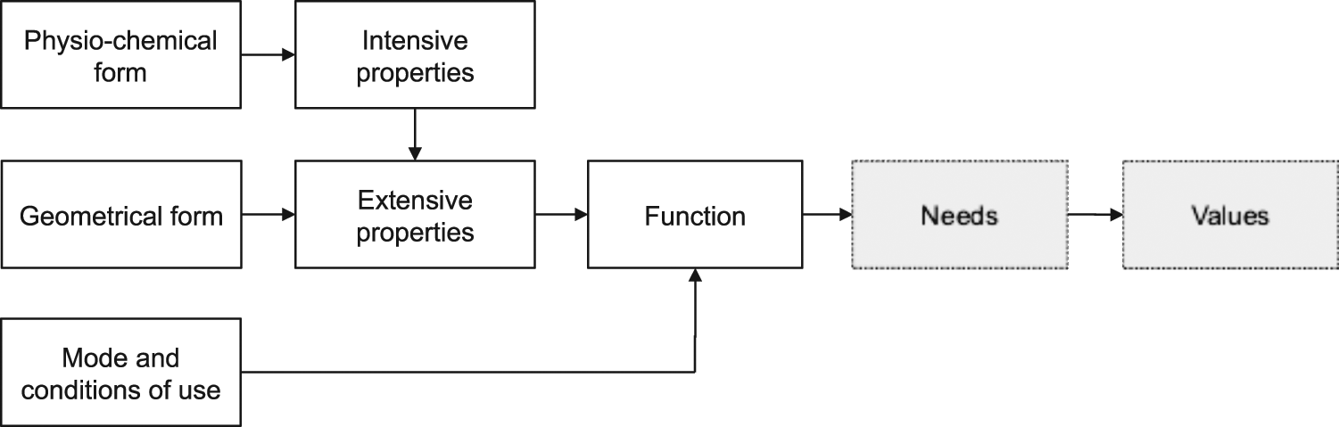
Function as a combination of form and mode and condition of use.
Normally, neither the design nor how it is to be used is known. When reasoning from function to form very little is given and very much is asked. It is an open process with many possible solutions. Such activity is inherently nondeductive; hence, it cannot be grasped in an equation. The designer’s skills and knowledge play a central role during the reasoning.
The designers’ reasoning depends on an understanding of the design problem, which is a driver for including the design problem in the product description. The result of this reasoning, that is, the DSs as well as the reasoning itself, is also described in the product description thereby forming a DR comprising the requirements, DS, and reasoning, which this article aims to support.
DR
Models containing more information than just the resulting design are fundamental in any product development that has reached at least some degree of complexity. DR is an approach to design, which emphasizes working with explicit representations not only of possible DSs but also of the reasons and processes behind them (McKerlie and MacLean, 1994). In other words, a DR is composed of the following:
The design intent that is the underlying reason why a certain artifact exists. It is the dreams, visions, objectives, goals, and intended behavior of the product. It describes the intentions behind the idea and the idea of the products, answering the question “why things are.”
The justifications for the design, the other alternatives considered, the trade-offs evaluated, and the argumentation that led to that decision (Lee, 1997).
Thus, DR, in a postdecisional perspective, answers the question, why things are and why things are the way they are.
A DR that completely contains the reasons and answers is not possible to reach. Andersson (2003) claims that the complete rationale for a product cannot be elicited and represented, as it is not a finite task. The completeness is also limited (Almefelt, 2005) for two reasons: requirements are in practice often incomplete and conflicting, and individual requirements are not static throughout a development project (rather, they change in one or more steps).
F-M model as a carrier of the DR
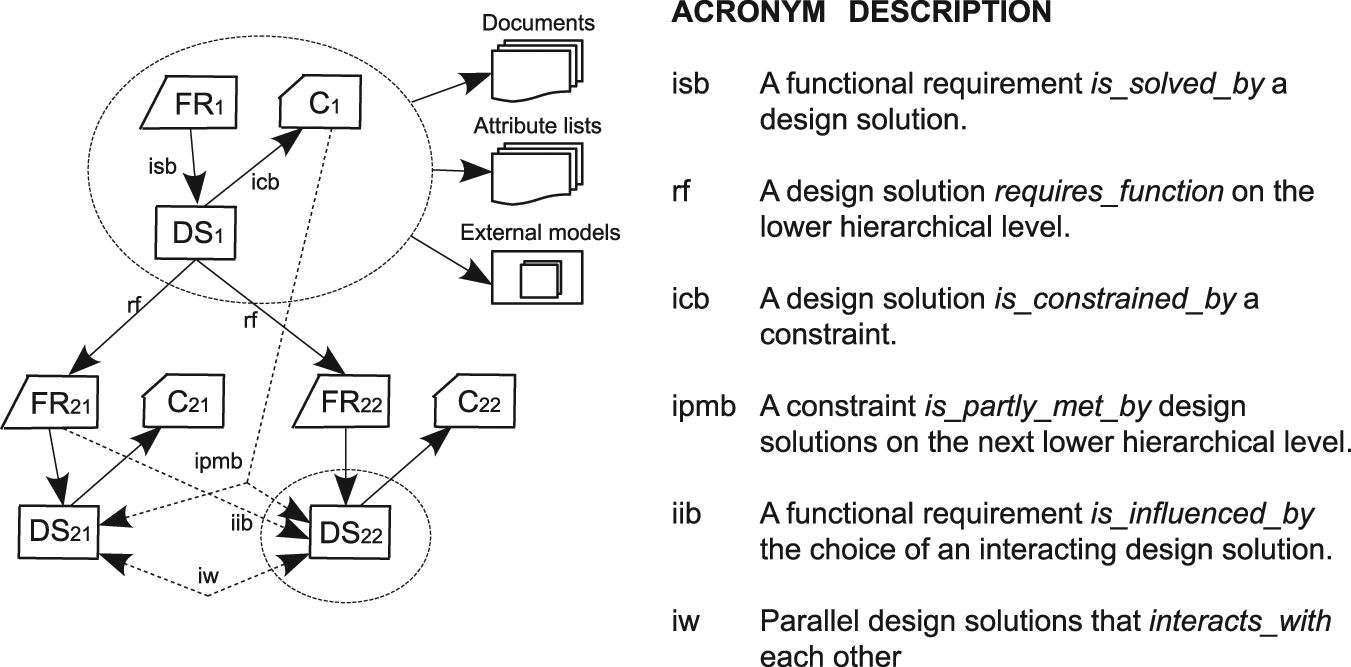
The basic idea of this article is to use an F-M model to represent the DR. The F-M method is a systematic way of finding DSs that fulfill functional requirements (FRs). The F-M model (or F-M tree) describes both requirements and solutions supporting a systematic design approach as shown in Figure 3.
Extended function-means tree.
The F-M tree is also a representation of Hubka’s law, which states, “The primary functions of a machine system are supported by a hierarchy of subordinate functions, which are determined by the chosen means.” It has evolved over time, having originally been developed by Tjalve (1976) and Andreasen (1980). Schachinger and Johannesson (2000) contributed with constraints decomposition in the F-M tree. In an analogy to the F-M tree, axiomatic design (Suh, 1990) describes the zigzagging between FR and design parameter (DP). The zigzagging points out the fact that a requirement cannot be decomposed into other requirements without identifying intermediate solutions.
A function in a system or in any of its elements is here defined as the effects, created by the elements or by the interactions between the elements, which result in the behavior of the system or the environments’ perception of it. DSs are defined as the designed technical artifacts that have the ability to create those effects. These definitions are in accordance with how a function and a function realizing organ are defined in the theory of domains and the related chromosome model proposed by Andreasen (1992). Note especially that a DS/means/organ is an abstraction of a design artifact that is chosen to realize a function. This means that there is an important difference between a DS/means/organ structure and a physical component structure (or BOM) and that special mappings between those two types of structures are needed. This mapping is not addressed in this work.
The term “FR” should be interpreted as a requirement to design the artifact and define the mode and condition of use that will make the design deliver the required function. FRs motivate the downright existence of a specific solution. The means, DSs, 1 are the physical (e.g. components or features) or nonphysical (e.g. service or software) entities that can possibly fulfill a specific FR. The role of the non-FRs (referred to here as constraints) is to delimit the allowed solution space for the FR-driven DSs. In contrast to FRs, constraints do not have specifically allocated DSs.
Results
Applying DR in platform development
The creation of a platform description that is composed of a number of cooperative configurable components gains from a built-in DR in the following two ways:
To describe the rationale behind the design (the previously discussed “why-information”);
To identify which subsystems to use when the system is composed of a number of subsystems, which is to be discussed here.
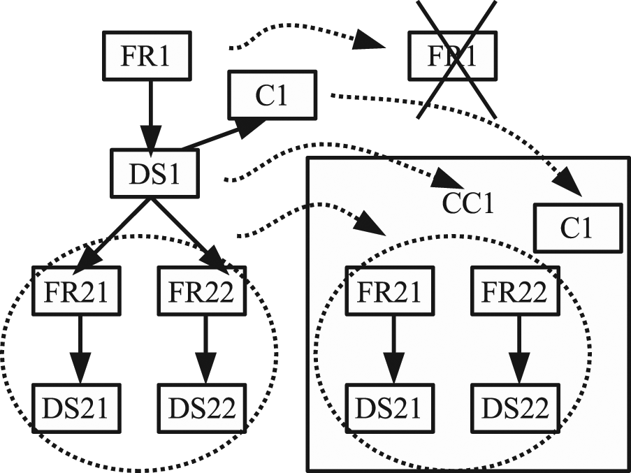
A description of a system can be formed in different ways according to what is considered feasible in the specific situation. However, two major alternative ways can be used when describing the system: (a) as composed by a number of subsystems or (b) autonomously (sometimes referred to as a leaf in a structure). The former gains from DR where the expectations on subsystem functionality can be matched with the potential subsystems presented functionality when subsystems are to be chosen as illustrated by Figure 4.
Matching of design rationale (FR–DS in CC1 vs. CC2) to support concurrent development of cooperative designs, for example, within a supply chain.
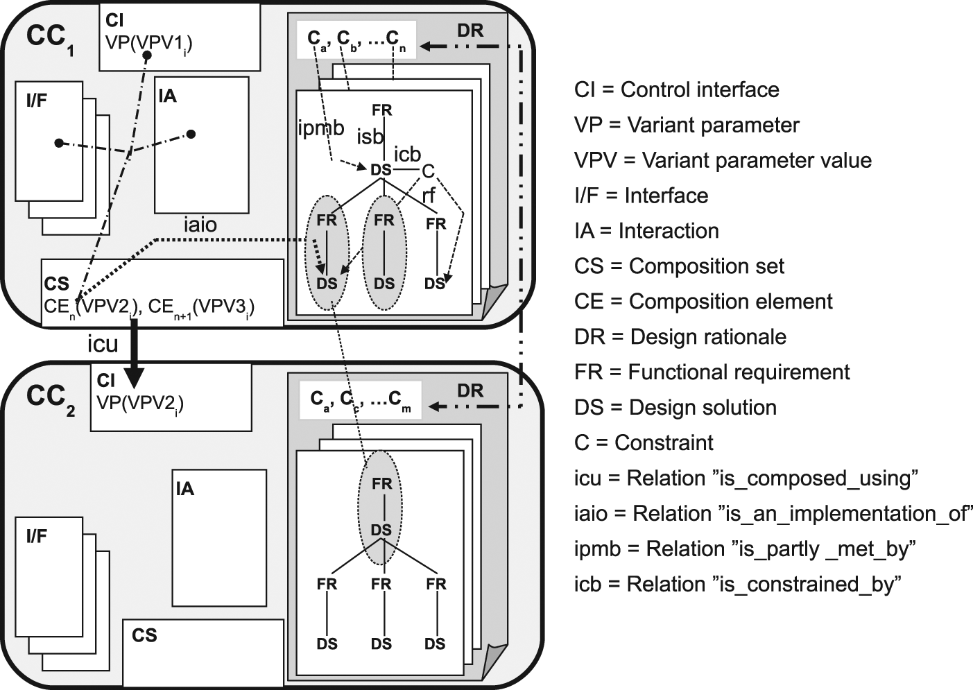
In this figure, CC1 represents a system that implements multiple functions, where each FR and DS, with required subrequirements and corresponding subsolutions (i.e. an F-M (here, an FR–DS structure), is developed. All such FR–DS structures, enhanced with decomposed system constraints, together constitute the DR of the system modeled as a configurable component. Instead of being an F-M tree with one FR-root, the DR is seen as a collection of F-M models with multiple starting points. The top DS, which is the configurable component itself, represents the complete design with a low level of detail (see Figure 4).
The subrequirements and subsolutions are useful when a designer is to define the configurable component’s composition. When a design is composed of other designs, this is described by a composition set (CS). A CS consists of a number of CEs where each describes a “wished” subsystem and a reference (CC_Reference) to the actual subsystem identified to meet this “wish.” In Figure 4, only a limited composition is presented. The first CE in CC1’s CS has an arrow to CC2, representing its CC_Reference, to illustrate how other configurable components are used in a composition. If a set of subrequirements and subsolutions matches corresponding items in the DR of an existing composition candidate (see Figure 4), it is a perfect choice. If no such candidate can be found, the identified subrequirements and subsolutions can constitute a plea for further development.
Matching between FR and DS couples in the DRs of different CCs is the basis for supply chain development collaboration between partners using CC models to describe their system designs. It aids, for example, an OEM to more efficiently and effectively incorporate a subsuppliers subsystem in its own hosting system. Note that it is sufficient for the FR–DS couple on system and subsystem levels to only “match.” It cannot be expected that the designers at the OEM and the subsupplier companies will formulate their DRs in the same way even if what they describe in fact is identical. Instead, when an engineering assessment says that two rationales are consistent, they can be said to match each other.
Enhancements and modifications of the F-M model
A configurable component is a model of an autonomous configurable system family encapsulating combined system families with different purposes (i.e. it has multifunctionality—like a Swiss army knife). A product platform, carrying a number of product variants (e.g. a sedan, coupé, and wagon car), can thus be achieved by a number of such configurable components. The different members (or possible system variants) that can be carried by the platform are determined by the bandwidths (parameter values’ ranges) of the involved configurable components. In order for a configurable component to benefit from the F-M model’s advantages, the latter must be adapted and applied in such a way that it can represent multiple similar designs realized by combined systems with different purposes.
Ability to represent multiple variants by one object
Variability is achieved by the configurable component by using parameters in its different internal objects. When a fraction of an F-M tree is used within a configurable component, it also becomes an internal object and is parameterized in a similar way. An F-M model (Johannesson and Gedell, 2009) has three building blocks: FRs, Constraints, and DSs. The parameters and parameter values can be associated with each of those building blocks. With these parameters and parameter values of the designs, a variability range is defined. The F-M model is also extended with methods to relate these variability ranges to each other. For instance, a DS may be restricted by a constraint expressed by an “is_constrained_by” relation. The DS will then define the constraint that restricts it. It will also define how its variability range, for each and every value, is restricted by the constraint’s variability range.
Ability to represent multiple functions by one object
The F-M model’s traditional approach is to start with one FR and successively elaborate the design based on that. That approach may fit a complete design with one over-all function, that is, designs that, within their scope, deliver functions that do not seem to relate to each other.
In Figure 5, an example from the automotive industry is used to illustrate this. A windscreen (CC1) on a car shall fulfill two functional requirements and one constraint; separate the interior climate from the outside climate (FR21), while maintaining visibility (C1), and to accommodate the rear view mirror (FR22). Traditionally, the left of Figure 5 is to be used where FR1 as well as DS1 is to be identified. Instead, the windscreen system, modeled as CC1 in the right figure, is given the role that DS1 has in the left figure. The functional requirement FR1, which is to be fulfilled by DS1, is then to be found in another CC that will be using CC1 for its realization. Consequently both FRs in the right part of Figure 5 are starting-points for separate F-M models. Such multiple F-M models in Figure 4 are illustrated as multiple sheets stacked on each other.
A traditional function-means model (left), modified with multiple starting points (right).
The ability to exclude FR1 and DS1 does not limit the designer to include FR and DS on a higher, super-system level, or on a lower sublevel, if that is considered useful.
Improving the transparency of how constraints are met
A constraint can have two types of relationships in an F-M model as follows (see Figure 3):
A DS has the relationship “is_constrained_by” to a constraint on the same hierarchical level;
A constraint has the relationship “is_partly_ met_by” to a DS on a lower hierarchical level.
These relationships do however not contain information as to what extent the DS on the lower level meets the constraint on the higher level. An example from the case study concerns a design’s flammability. To meet the requirement placed on the design as a whole, the flammability of most CEs is far below the overall constraint. This is a choice made to compensate for the very high flammability of one of the CEs. A special object, “constraint allocation” (see Figure 6), is added to the F-M model to describe such decisions. In addition to the relationship to the constraint to be allocated, constraint allocation contains a number of relationship pairs (DS and constraint) as shown in Figure 6.
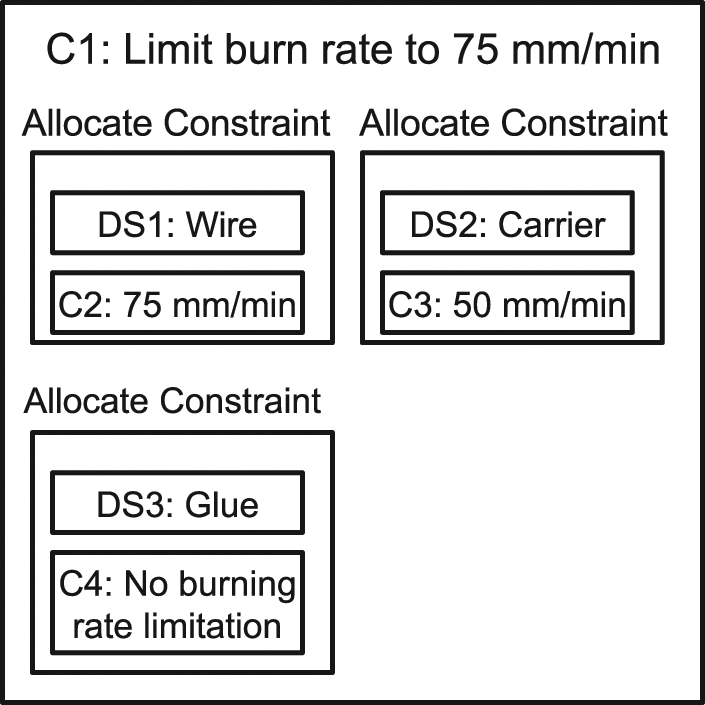
A constraint allocation object where a constraint (limit burn rate to 75 mm/min) is differently allocated to lower level constraints and DSs (screen dump from the AKM application, see the “Seat system to illustrate a DR that supports composition” section).
Relations between objects represented as explicit objects
The introduction of the constraint allocation indicates the usefulness of an object when describing the reasoning behind a relationship. Similarly, an object is used to represent every relationship (one object type for each relationship type) within the embedded F-M model.
The “is_solved_by” relation that relates an FR and a DS is used to illustrate this explicit way of modeling relations (see Figure 7). In this figure, the vaguely defined arrow is replaced by an object. That object can contain the reasoning why the DS is considered a good solution to the FR (an essential part of a DR). The object also holds the relation to the FR that it meets (Meets_FR) and the DS that is used to solve the problem (Uses_DS), as well as a potential mapping of their parameters. The black diamonds at the start of the arrows are a UML (2012) syntax that defines that the relations are an integrated part of the is_solved_by object.
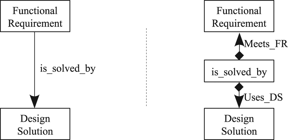
The relation in the left figure is described more explicitly in the right figure.
The explicit relation object encourages an understanding of requirements and DSs as persistent objects that exist independently of each other and of contexts. The designing includes identifying the design’s relevant requirements in the almost infinite “sea of requirements” and similarly—the solutions.
Support during design and production life cycles
An information-rich product description has the ability to support a number of activities during a design’s life cycles. The following sections will present some examples of how product development can take advantage of a product description as presented in previous sections.
To define which variants that shall be included in the product program (or product offer) is facilitated by a method that presents the set of variants in a user-friendly way. The configurable component’s ability to represent multiple variants as a parameterized one gives an easy accessible overview of the design.
Extending the parameters with new parameter values, which increase the design’s scalability, can create new design variants. Design rules and evaluation models included in the product description improve the designer’s ability and can be used to either create and evaluate more ideas or reduce the development time;
Classical use of the product description as an information carrier to both prototype and series production is a given usage.
To use a product description both as a source for production and as a design tool raises issues. They can be seen as each other’s antipodes, both from a perspective of causality between input and output and from a perspective of business. When a configurable component model is used to configure predefined instantiated variants, the deductive causal relationships between input and output are used. This contrasts to designing, which is a divergent search for DSs. Still, the product description will support the design activities, when it is used as a source for design proposals that are derived based on deduction.
Company knowledge, for example, found in handbooks and reports as well as skilled personnel, can be used as a base to formulate equations (causal dependencies) that are incorporated into the configurable component model in order to propose DSs. These generated design proposals are then to be evaluated by the designer. A product platform with configurable components will then contain descriptions of design variants and rules that may be used to create further variants.
Real-life industrial examples
The cases presented here are used both to show the applicability of the framework on various “levels” in the supply chain and to exemplify collaborative concurrent design in the supply chain. The examples presented are from the automotive industry (one automotive company and one of their tier-2 suppliers) and are chosen to illustrate a subset of a car while focusing on the vertical collaboration between OEM and subsuppliers as well as how a system is formed using subsystems. Each of the examples has its specific focus while they together form an integrated model even if only a subset of a design is modeled. The systems described are as follows: car, interior, seats, seat heating, heating element, and wire. These systems are described in a variable degree of details, and other systems (e.g. seat structure and seat foam) that interact with these listed systems are only represented as stubs, if represented at all.
The work is divided into three work packages to evaluate the presented methodologies applicability to represent reasoning behind design choices and how to support designing. The examples focus on the following:
Describe an OEM’s platform including a DR, or to be more precise, to describe a subset of the automaker’s seat system and how it is composed of subsystems.
Describe a subsupplier’s platform including a DR, where one of the aims is to evaluate similarities and differences compared to modeling on the OEM level.
Extend the subsupplier’s platform description with an ability to propose (or generate) new DSs based on a DR that include the company’s design rules and guidelines, in order to meet a new set of requests from customers, for example, OEMs.
Seat system to illustrate a DR that supports composition
The scientific aim for this case study is to make initial verification and validation when implementing a DR using the F-M method. The company’s aim is to be introduced to a method new to the company.
A car seat is chosen as a modeling object. A seat is an example of a design that evolves over time, where new DSs are being introduced between seat generations, while others are maintained over time. Additionally, the studied companies’ product program includes a huge number of variants. Together, this makes it an interesting modeling example to illustrate a DR. The sketches in Figure 8 illustrate the variability aspects such as different seat foam and under seat mechanics.
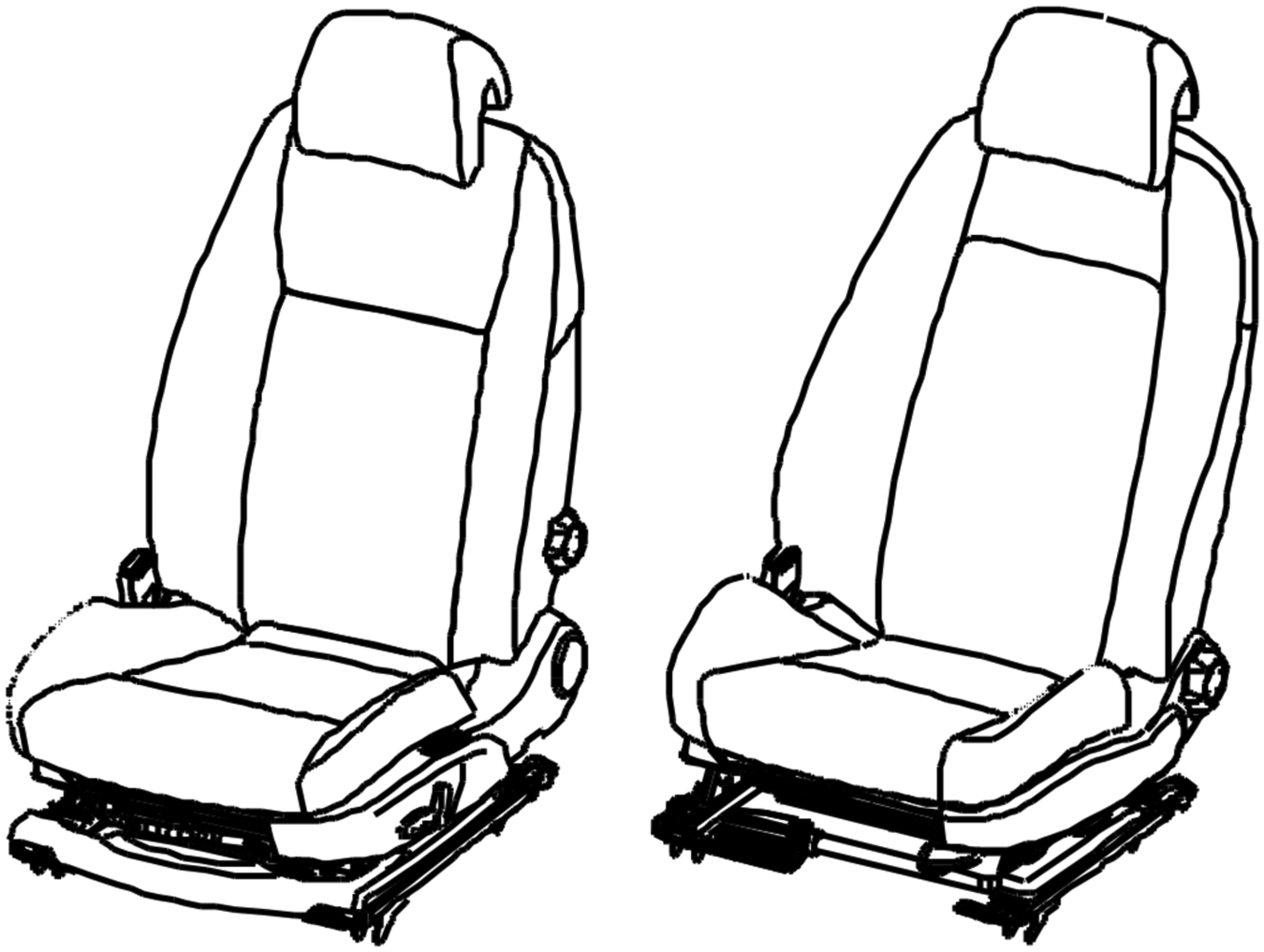
Two seat variants illustrating differences in foam shape and maneuverability (under seat structure and lumbar support adjustment knob).
Before looking into modeling details, the issue of the models’ completeness is to be considered. The model of the seat system is created to meet the needs and purpose relevant for the creators and users of that model. The information included in the description, and more specifically in the DR, is based on how the design is perceived in its context. The description content is formulated with a focus on the questions and issues that arise on the “level” complete seat unit. In other words, the description shall not be completely exhaustive. Consequently, the seat system description is considered completed when (1) enough details are included in the DR to identify which subsystems to use and (2) the CS and the CEs have been referenced to the subsystems. To summarize, completeness is a relative term that is related to expectations.
The data collection, on which the model is based, is performed, as a series of interactive workshops where the main tool used is whiteboard, pen, and paper. The researcher and a highly skilled designer from the car company meet for an hour or 2 on several occasions. Data collected as notes and sketches were, after each meeting, fed into a software application (Active Knowledge Modeling (AKM), 2012) and presented as printouts at the following meeting. The AKM tool’s way to enable the user to define the data model, on which the modeling is based, is a valuable feature when developing and evaluating the data model.
The result from these work sessions is a description of the seat system on a rather high level of abstraction. A number of requirements and concepts are identified to, for example, handle comfort, maneuverability, safety, and esthetic aspects. A subset of the seat’s DR, chosen due to its impact on the seat heat element, is presented in Figure 9 as two F-M branches (a chain of parameterized FR and parameterized DS).
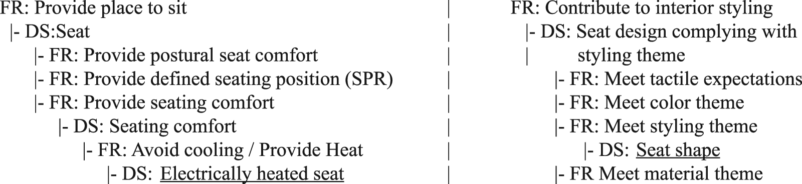
Two branches of the seat’s design rationale describing the reasons for the existence of the system and one interacting DS that restricts the heat element’s shape (both are underlined).
On the left of Figure 9, the reasoning for the existence of the heat element is described. On the right of Figure 9, the reasoning behind the seat shape is described, which limits the size and shape of the heat element. From parametric point of view, the two branches differ. In the right of Figure 9, the DS “DS: Seat shape” has a number of parameter values (“Standard,” “Sport”) that meet the requirement to offer different styling themes, that is, the seat shape’s parameter is chosen based on the meet styling theme’s parameter set. In the left of Figure 9, the parameter set of avoid cooling/provide heat is both used in the same way and also used to control a conditional use on the relation between “FR: Avoid cooling/Provide Heat” and “DS: Electrically heated seat.” In other words, some sets of requirement are met by including a seat heat function, whereas others are met without it.
It shall be noted that the identified DSs (electrically heated seat and seat shape) are not further elaborated here. Instead, they are used to identify feasible subsystems (Seat Heat) as further discussed in the next section. The different wording, which might be perceived as a mismatch or error, is an example of terminology adequate within each context as discussed in the last paragraph in the “Support during design and production life cycles” section.
Applying DR on a subsupplier’s platform
The scientific aim for this case study is to evaluate the applicability of the method at a subsupplier and, more specifically, to compare the applicability of the method when applied at an OEM company compared with a subsupplier company. The company’s goal is to evaluate the method as well as learn more about their designs by using the method.
The setup for this case study is similar to the one previously presented, although experiences gained contribute to the setup of this case study. Besides the obvious change of focus to their company’s products, they engaged more engineers, probably to be able to validate the usefulness of the method in their design process in a better way.
The main activities involved were workshops in which representatives from Chalmers and tier-2 company together created a heat element model. The modeling sessions/workshops can be described as reversed engineering. The Chalmers representatives, who were unfamiliar with the design, asked questions like what is that, why is it there, or what does it do while pointing at a detail (a DS) on a heat element. The design experts explained the design, and the answers were successively transferred to model elements and fed into the model using the software application AKM. The work progressed in the following three major steps:
Instantiation of the system (the configurable component) itself and major structure elements within it, such as CS and CE;
Creation of an unparameterized (i.e. single variant) DR, using the procedure described above;
Generalization of the DR to describe multiple variants, thereby forming a configurable platform description.
The last step required quite a lot of considerations. When comparing two design variants, the designs could use different DSs. Was it an intentional variation as a consequence of different requirements (and if so, what were the requirements), or was it accidental? The best practice may change over time, and equally the designs, even though the requirements are unchanged. Different designers have created designs over many years, which may be a reasonable explanation. However, there might have been some requirements that were overseen. To figure this out requires engineers with deep knowledge and preferably long experience of the product. Although time-consuming, the discussion about different DS alternatives increased the amount of details in the model. Details that might otherwise have been overlooked were identified and documented. Besides the reverse engineering, a top-down approach was applied for the customer requirements, which were especially useful to identify constraints.
During the modeling sessions, when the DRs were identified and documented, information was found that could not be handled with the previous methodology. The identified needs initiated parallel activities to generalize the methodology based on the initial models and theories (exemplified in the “Enhancements and modifications of the F-M model” section). The findings were then applied in the continued modeling, and the results were verified and validated together with company’s engineers.
DR to support engineer-to-order
The third and last case study aims at exemplifying how a DR can be used as a knowledge source capable of generating new designs based on a new parameter value set of requirements. The company needs ability to make rather rough estimation on their capability to meet a new request, and more specifically, if their existing part library can be used to produce the new design. Even though this need has arisen from the company’s sales support, it is not a configuration task (or sales-to-order) but instead an engineer-to-order activity as it includes designing of completely new design variants.
The DR is extended with equations based on knowledge found in the company’s quick reference guides and handbooks that relates a design’s characteristics to the DSs. Additionally, the software application that is used to describe and present the DR in the previous presented case studies (AKM) is extended with an ability to calculate new DP values based on these equations in combination with a new set of values of the requirement parameters. With these extensions in place, the product description has two modes of operation: (a) a storage of existing designs, which can be retrieved by a configuration expression, and (b) an ability to create new design variant proposals. A mix between these modes is also possible even though it is not a seamless transit between the modes of operation.
Figure 10 presents an overview of the case study. Before discussing how to generate designs based on the model, just let us recap how designs can be retrieved.
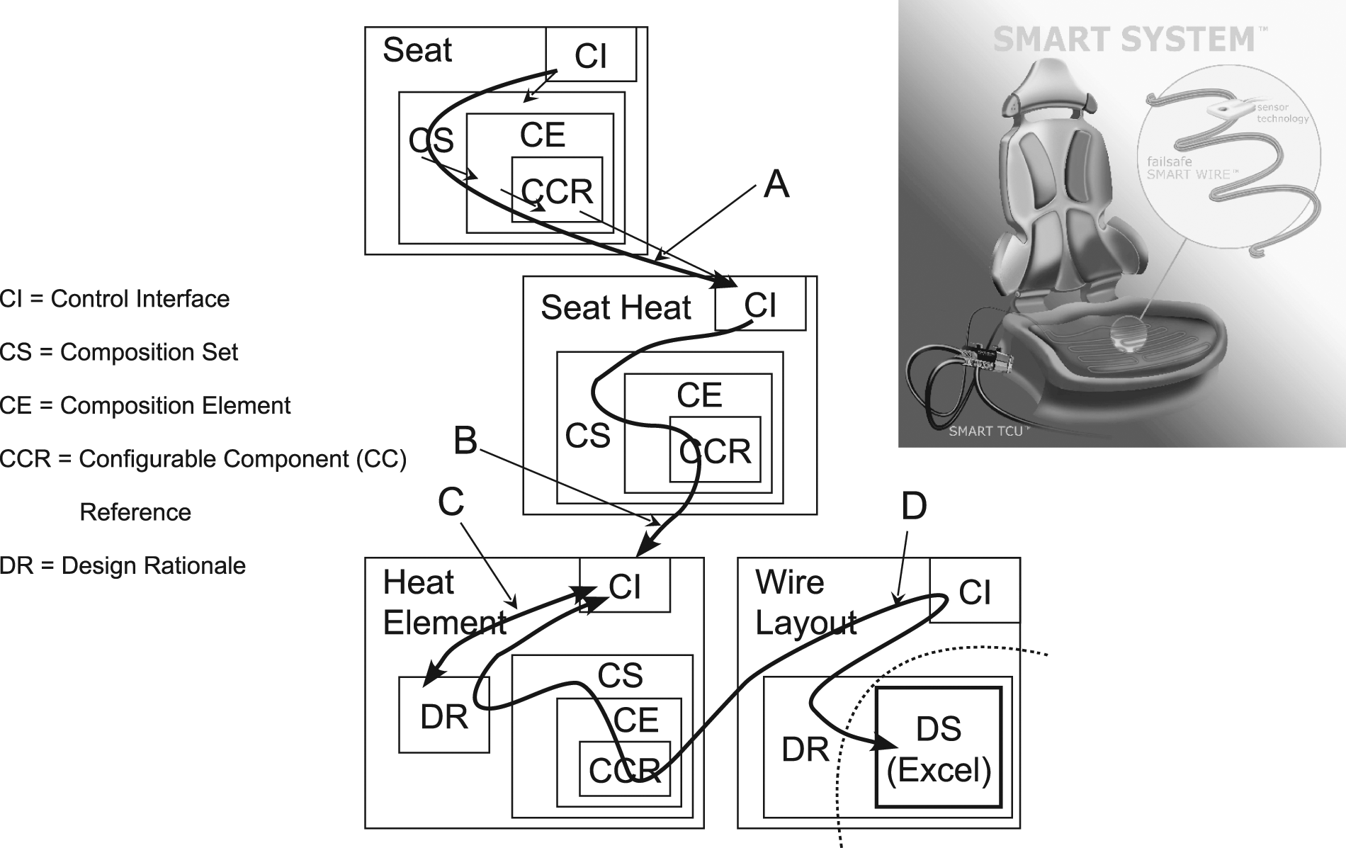
Schematic overview of the information flow during configuration and generation.
By applying a configuration expression to the control interface, the system (including its composition) is configured, which means that its subsystems also will be assigned values on their control interface and so on, until the model is completely configured. In more detail, the configuration expression is used to configure the “Seat” and its internal elements using composition mechanisms (CS, CE, and CC-reference (CCR)) as discussed in the “Applying DR in platform development” section). This will apply configuration expressions to the systems that the seat is composed of (see Arrow A in Figure 10). “Seat Heat” will configure “Heat Element” in a similar way (see Arrow B in Figure 10). The DR is not directly used in this mode of operation but indirectly used as the composition decisions that have previously been made (and documented in the composition) are based on the DR.
In this case study, the seat description includes both an ability to configure a number of seat variants as requests for subsystems and also some seat variants that are not possible to configure as the design is under construction (it is incomplete). In other words, the chain seat–seat heat–heat element–wire layout is broken at some place because the requested design variant is not yet defined.
In Figure 10, it is illustrated how, in the absence of previous decisions of which heat element to chose, design data are passed over to the heat element in order to, in return, receive a design and some of its key design characteristics. Most of the seat heat’s control interface parameters are given values selected from their parameter value sets, for example, system voltage and heat regulation principle. However, the shape of the foam, on which the seat heat element is to be assembled, is given as a three-dimensional (3D) model as it is a new shape.
In order to answer the question whether a heat element can be produced from the parts already in use in the production facility, and still meet the request, a rough wire layout design is made in the following way:
The information flow in Figure 10 is initiated by assigning values to the seat’s control interface. Along with the selected parameters values, the 3D model for the seat is passed to seat heat (Arrow A).
Seat heat has two similar compositions of heat element: one for the seat element and the other for the backrest element, which means that heat element will be instantiated twice, both represented by Arrow B.
The heat element is a rather thin and flat part that during assembly of the seat, it is stretched and mounted on the nonflat seat shape. First step toward finding a design is to approximate the 3D seat shape to a two-dimensional (2D) shape in accordance with the stretch limitations described in the heat element’s DR, which is implemented by a software application (represented in Figure 10 by Arrow C).
Heat element calls the wire layout’s DR for the design rules that limits the wire layout. A center wire length is calculated, based on the previous calculated 2D area, which is returned to the heat element (Arrow D). This knowledge is in the study implemented as an Excel spreadsheet, to indicate that this implementation of the configurable component concept is an open system that allows for communication with other systems but also from more practical reasons—it is quite easy to integrate Excel and use it to write equations.
The heat element’s DR knowledge of the production process includes knowledge of the limitation between center wire length and the real wire length (the production process does not put wire straight on the centerline but sick-sacks wire following the centerline). With the contribution from the wire’s DR (set of wire dimensions), the equations in heat element are used to find a wire type and wire length that meets the requirements (if a solution can be found).
Summary of results
The research presented answers the research questions and contributes to the configurable component framework as follows:
RQ1: How could F-M trees be used as carriers of “why-information” within product platforms with platform elements defined by configurable components?
The configurable component is extended with elements to achieve an ability to represent a design’s DR as an integrated part of the design description.
It is described how to apply these elements when a design is to be described by creating a DR.
RQ2: How could configurable components carrying “why-information” support platform design reasoning, and thereby designing?
The DR supports design composition and thereby the creation of product structures.
The modeling method is applicable to describe any design and on any “level” in a supply chain, that is, supports platforms independent of position in the supply chain.
It is exemplified how the DR can contribute to generating new designs being, an information source.
Discussion and conclusions
The approach used to solve the problems, expressed as research questions, is to extend the data model’s ability to represent a system, or more precisely, an ability for the model to represent not only the system itself (including possible modes or internal states) but also what its purpose is and the environment or context it is intended to interact with. By incorporating a DR in the configurable component model, the model has been given ability to include answers to the question “Why is the design as it is.”
The F-M tree, proposed to act as a DR within a configurable component, has been adapted and applied to comply with the scope of the configurable component concept (in other words, to describe an encapsulated configurable system family composed of combined system families).
In order to ensure the applicability of the proposed solution, the proposed model has been implemented in a tool to form a demonstrator. The demonstrator has also been extended to be able to generate new design variants based on the DR and implemented rules that describe the relation between the DS and the design’s characteristics. Using the demonstrator, real cases from the automotive industry have been described. The demonstrator has been used both to evaluate the applicability of the method in companies on different levels in the supply chain and to explore the possibility to use the DR more actively when creating new designs.
The results are verified by applicability and verification by acceptance. The proposed modeling approach has been able to model the case studies, thus, meeting the research applicability criterion. Verification by acceptance is to some extent met, as the participating industrial partners appreciated the approach and the outcome of the modeling work sessions performed in collaboration with the researcher. The participants gained further knowledge about their own products when they described the reasoning behind the design decisions, which was found to be very valuable for future design work. Indeed, when describing his company’s products as a configurable component, one of the industrial participants discovered a potential product combination currently missing in the product program.
To summarize the results, the first research question—how an F-M tree can be used as a carrier of “why-information” within a configurable component—can be answered with: “Yes it can,” but to effectively handle the case studies it needs to be adapted and applied appropriately as shown in this article. The second research question—how configurable components carrying “why-information” could support platform design reasoning—is exemplified both by the case studies where the DR part of the product description formed an arena for design discussion, thereby supporting the design activities, and by the semiautomated example presented in the third case study.
The first two case studies show a similar applicability of the method for both the subsupplier and the OEM. Each description (the OEM’s and the supplier’s) is based on issues relevant for their context. As a consequence, the descriptions will differ in their wording and level of detail even though the descriptions are partly describing the same thing, or to be more correct, when the designs have converged (the design is set and done) some configuration of the seat and the subsystems composing it will have the same meaning. In other words, the statements made in the “The configurable component concept” section concerning the framework’s ability to support concurrent engineering in the supply chain have been confirmed by the case studies.
Monolithic and centralized design descriptions tend to become obsolete due to difficulties to maintain them. The approach presented here, a decentralized design description that was created by organizations describing their design according to their context, will be easier to overview and maintain compared to a centralized one. Even though this is an important driver for the framework, it is still only partly verified and will require future research to be confirmed.
Footnotes
Funding
This work was carried out within the Wingquist Laboratory VINN Excellence Centre at Chalmers University of Technology. It was supported by the Swedish Governmental Agency for Innovation Systems.