
Abstract
This article presents a template-based modeling methodology for the effective construction of a virtual plant that can be used for the virtual commissioning of a programmable logic controller. For virtual commissioning, the corresponding virtual plant, consisting of virtual devices, is required to interact with the input and output symbols of a programmable logic controller. In other words, the behavior of a virtual device should be the same as that of the real device. Conventionally, discrete event systems specifications formalism has been used to represent the behavior of a virtual device. However, modeling using discrete event systems specifications formalism requires in-depth knowledge of simulation as well as significant amounts of time and effort. One of the key ideas of the proposed methodology is to provide a device template model representing the relations between the tasks of a device. The proposed template is very intuitive and can be used to generate a comprehensive behavior model of a virtual device. The proposed approach has been implemented and demonstrated for a robotic cell.
Introduction
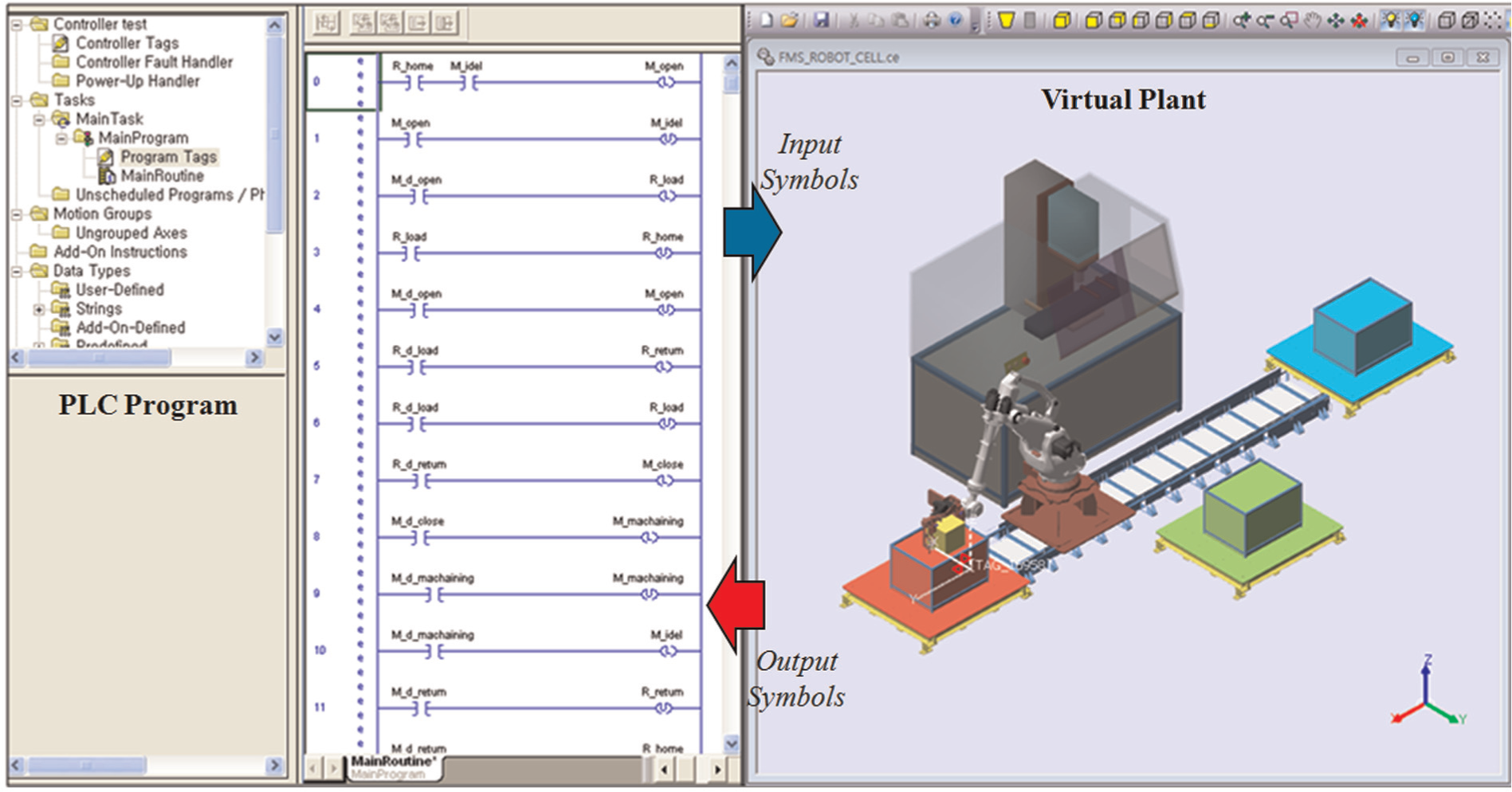
To survive and prosper in the modern manufacturing era, manufacturers must quickly and effectively respond to shifts in the global markets by delivering new, high-quality products at low costs in a short span of time. Therefore, manufacturing systems must possess sufficient responsiveness to adapt their behavior efficiently toward a diverse range of circumstances (Choi et al., 2010a; Kwon et al., 2009). Virtual commissioning technology has been widely accepted in recent times to respond to demands, such as high productivity and production flexibility (Choi et al., 2010b; Drath et al., 2008; Hoffman et al., 2010; Pellicciari et al., 2010; Thramboulidis, 2004; Xu et al., 2000). Virtual commissioning involves replicating the behavior of one or more pieces of hardware within a software environment. In a manufacturing system, the hardware controller (programmable logic controller (PLC)) and the virtual plant correspond to the hardware and the software components, respectively. Figure 1 shows the concept of virtual commissioning for a manufacturing system (PLC simulation). The ultimate goal of virtual commissioning is to provide an automation engineer with a virtual plant (software environment) to validate their PLC ladder logic, prior to its real implementation; this consequently improves quality and enables a seamless transition from the virtual environment to the real one.
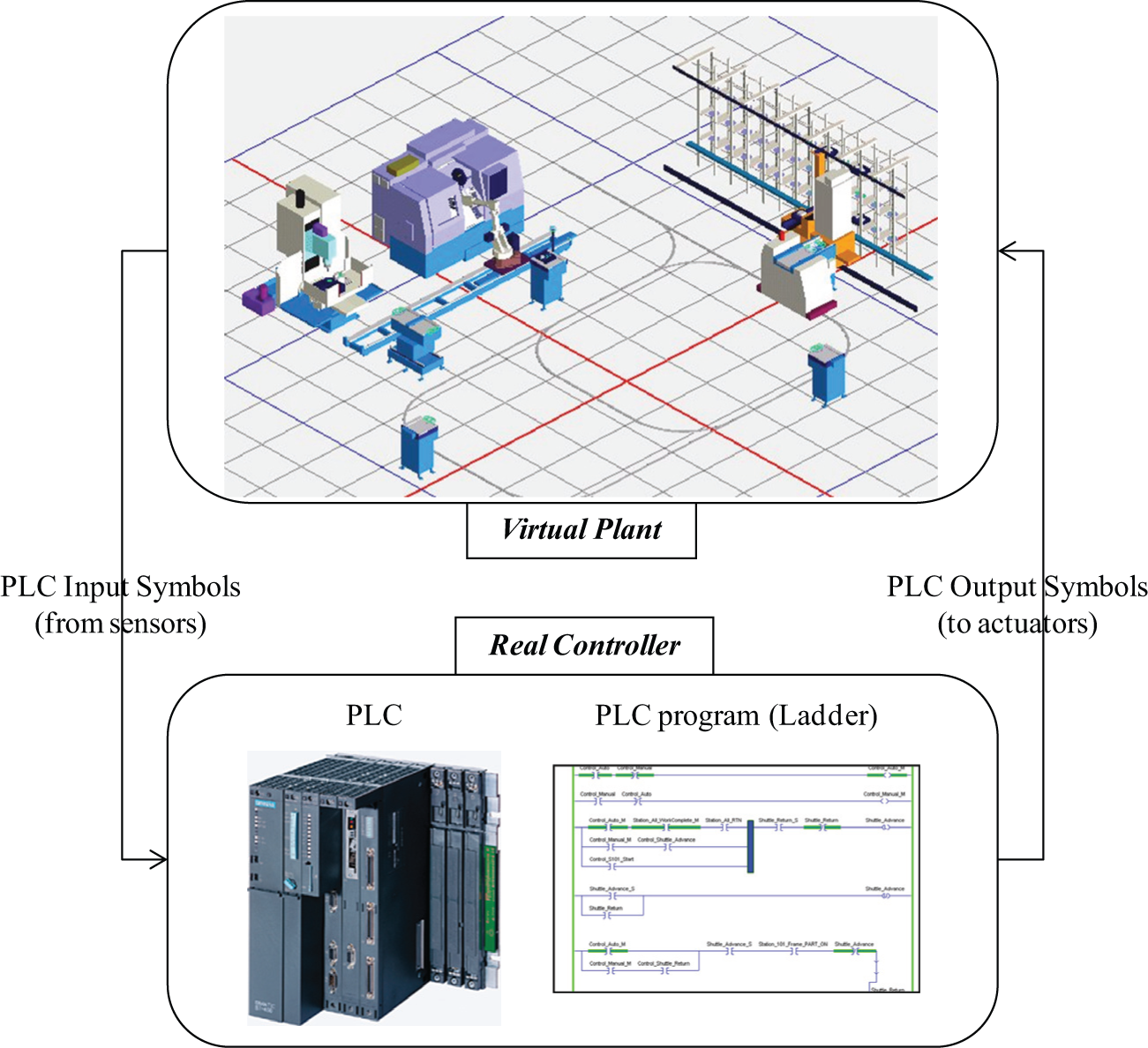
Virtual commissioning for a manufacturing system (PLC simulation).
In the past, the application area of virtual commissioning was constrained to small-sized manufacturing cells because of poor computational power. However, recent developments in computer technology have rendered it possible to apply virtual commissioning technology to considerably large manufacturing systems (line, factory). As a part of this revolution, offline programming of robots and verification of control programs (Han et al., 2011; Hibnio et al., 2006; Park et al., 2010) using virtual device models have emerged in various industries.
Various machines that operate simultaneously in a manufacturing system are usually controlled by PLCs, which is currently the most suitable and widely employed industrial control technology. A PLC emulates the behavior of an electric ladder diagram. PLCs, which are sequential machines, use an input/output symbol table and a scanning cycle to emulate the working of parallel circuits that respond instantaneously. A program that is executed on a PLC continuously executes a scan cycle. The program scan solves the Boolean logic related to the information in the input table with that in output and internal relay tables. In addition, the information in the output and internal relay tables are updated during the program scan. In a PLC, this Boolean logic is typically represented using a graphical language, known as the ladder diagram.
Previous approaches on PLC programs can be categorized into two groups: (1) verification of a given PLC program (Bauer et al., 2004; David and Alla, 1994; Gourcuff et al., 2006) and (2) generation of a dependable PLC program (Fray, 2000; Jafari and Boucher, 1994; Lee and Hsu, 2000; Pavlovic et al., 2007). In the first group, various software tools have been developed for the verification of PLC-based systems via the use of timed automata, such as UPPAAL2k, KRONOS, Supremica, and HyTech. These are mainly applicable for programs written in statement list language, also termed Boolean (Manesis and Akantziotis, 2005). These software tools verify the PLC programs to a certain extent; however, they remain limited. Because their focus is on checking theoretical attributes (safety, liveness, and reachability), it is difficult for users to determine whether these PLC programs actually achieve the intended control objectives. In the second group, many researchers have focused on the automatic generation of PLC programs from various formalisms including state diagrams, Petri nets, and Icam DEFinition for Function Modeling (IDEF0). These formalisms can help the design process of control logics. However, it remains a challenge to find hidden errors, which is the most difficult part of verification of a control program.
For the discovery of hidden errors in an intuitive environment, virtual commissioning should be based on a virtual plant that interacts with the input and output symbols of a PLC. In other words, the behavior of a virtual plant should be the same as that of the real plant. However, one of the major drawbacks of this approach is the excessive amount of time and effort involved in the construction of a precise virtual plant model. The benefits of virtual commissioning have long been recognized. However, despite this, there has rarely been a focus on the effective construction of a virtual plant for virtual commissioning. Usually, the construction of a virtual plant requires considerably more time, when compared to PLC programming. This serves as a motivation to explore the possibility of finding a more effective construction methodology for virtual plants using template models of virtual devices.
The objective of this article is to develop a template-based virtual plant modeling methodology for virtual commissioning. The overall structure of the article is as follows. Section “Approach to template-based virtual plant modeling” addresses the overall approach to the template-based virtual plant modeling. Section “Template-based modeling” describes a detailed construction methodology for a template model that can be synchronized with a control program. Section “Examples and illustrations” provides an example and has related illustrations. Finally, the concluding remarks are given in section “Discussion and conclusion.”
Approach to template-based virtual plant modeling
As mentioned already, virtual commissioning in manufacturing industries targets to provide a virtual plant to an automation engineer to validate their PLC control program prior to real implementation. A PLC is a dedicated computer system controlling a plant through input and output symbols (signals). While output symbols trigger tasks in manufacturing devices, input symbols are used to capture the present status of the devices through various sensors.
For the virtual commissioning of a PLC, the corresponding plant model (the counterpart system) is required to interact with the input and output of the PLC. The behavior of the plant model should be the same as that of the actual system to achieve PLC verification. Because a manufacturing system consists of various devices, including robots, transporters, jigs, solenoids, proximity sensors, and light sensors (Groover, 2006), we can consider a plant model as a set of device models. To build such a device model, the discrete event systems specifications (DEVS) formalism (Kim, 1994; Zeigler, 1984) has been used conventionally. The semantics of the formalism are highly compatible with the object-oriented specifications of the simulation models. We use the atomic model of the DEVS formalism to represent the behavior of the device model. Formally, an atomic model
The atomic model consists of three sets and four functions. The four functions in the 7-tuple, namely
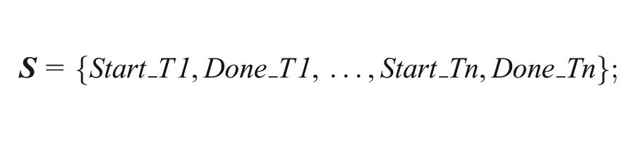
Before explaining the template-based modeling procedure of a plant model, let us consider the manual procedure to construct device models. To construct a device model, first, it is necessary to identify the set of tasks that are assigned to the device. The activation of each task is normally triggered by an output symbol of PLC programs. Following the identification of the set of tasks of a device, the state transition diagram, which defines an atomic model of the DEVS formalism, can be extracted. Figure 2 shows a simple example of an automatic guided vehicle (AGV) with two tasks, T1 (movement from p1 to p2) and T2 (movement from p2 to p1). Because the two tasks should be triggered by output symbols of a PLC, the AGV model must have two input ports, termed here as O_T1 and O_T2, as shown in Figure 2. Based on the set of tasks, it is possible to instantiate the state transition diagram. In this example, there are four states, Start_T1, Done_T1, Start_T2, and Done_T2. While Done_T1 and Done_T2 take external events from the input ports (O_T1, O_T2) for state transitions, Start_T1 and Start_T2 take internal events. The DEVS atomic model of the virtual device, corresponding to the AGV, can be described as follows:
Virtual device model of an AGV:
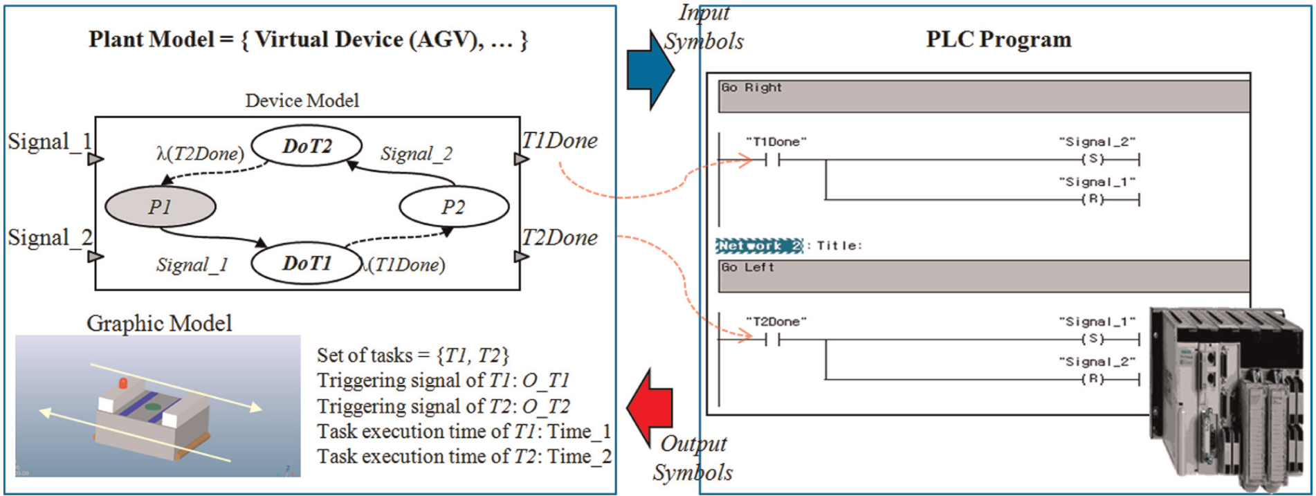
Virtual device model of an AGV.
After the virtual plant model is constructed, it is possible to perform virtual commissioning of a PLC. Although virtual commissioning of a PLC enables the intuitive verification of a control program, construction of a virtual plant requires considerable effort and in-depth knowledge of simulation. To address this problem, we propose a template-based modeling methodology for a virtual device.
We propose a template model for a manufacturing device, and the template should be able to generate an atomic model of a device. To develop a proper template, it is necessary to focus on the inherent attributes of a device in an automated manufacturing system. (1) Each device has a set of tasks, (2) a task is triggered by an output symbol of a PLC, (3) a device performs the tasks one at a time, (4) the completion of a task is notified through an input symbol of a PLC, and (5) a task, possibly, has succeeding tasks.
It is intuitively evident from the inherent attributes of a device model that a task of a device has two related PLC symbols—an output symbol and an input symbol. Triggering a task is accomplished by an output symbol of a PLC, and the completion of the task is notified through an input symbol of the PLC. Besides, there can be constraints on the execution sequence of the tasks. For example, study the AGV model shown in Figure 2. The AGV model has two tasks, T1 (movement from p1 to p2) and T2 (movement from p2 to p1). A possible succeeding task of T1 can be T2, and vice versa. In other words, T1 (moving to p2) cannot be performed consecutively because the AGV is already at p2 following the previously executed T1.
A single task involves two PLC symbols, and each task may have possible succeeding tasks. This information can be represented using a task table, as shown in Figure 3. The task table is very intuitive to engineers. Further, an in-depth knowledge of simulation is not required to comprehend the same. The key idea of this article is to generate the complete behavior model of a device using the task table. Consequently, plant models for virtual commissioning can be constructed easily. The procedure to generate a device model (atomic model) using a task table is discussed in the following section.
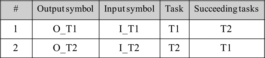
Task table of the AGV.
Template-based modeling
As mentioned already, a task table includes tasks, input/output symbols, and the constraints on the execution sequence of tasks. We propose a “device template” model for representing the task table formally. Formally, the device template model is specified by a 4-tuple:
Device template
P(
The proposed device template consists of three sets and one function. The three sets (
Device template model of the AGV
Thus, such a definition of the task table shown in Figure 3 is very intuitive to engineers who lack in-depth knowledge of modeling and simulation. Once the device template model is constructed, it can be used to generate an atomic model of the device. The atomic model generation algorithm is addressed as follows.
■ Generation of an atomic model from a device template model
// Input: a device template model,
//
//
//
// Output: an atomic model of the device,
Step 1) Input/output events set: Simply assign the same input/output sets of the device model.


Step 2) Sequential states set: For each task (Ti ∈
Step 3) Internal transition functions: For each task (Ti ∈

Step 4) External transition functions: For each task (Ti ∈
Step 5) Output functions: For each task (Ti ∈
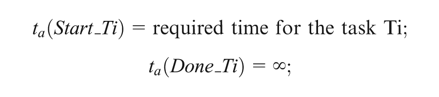
Step 6) Time advance functions: Define a time advance function for every state. It is to be observed that the duration for a state having no internal transition functions becomes infinite (∞), because it cannot escape the state without an external trigger.
While an atomic model consists of three sets and four functions, the proposed device template model includes three sets and one function. The three sets of an atomic model can be intuitively extracted (Steps 1 and 2) from the input/output symbols and tasks. The four functions of an atomic model are extracted (Steps 3–6) from the task information. In this way, we can effectively construct a precise virtual plant model that is suitable for virtual commissioning of a PLC.
Examples and illustrations
The prototype of the proposed template-based modeling approach has been implemented and demonstrated for a robotic cell. The C++ language was used in a Visual Studio environment, with OpenGL being used for graphical rendering. A robotic cell, shown in Figure 4, consists of two input stations (A and B), a computer numerical control (CNC) machine (C), an output station (D), and a robot. If a part arrives at one of the input stations, the robot moves the part to the CNC machine. After machining of the part, the robot moves the part from the CNC machine to the output station.
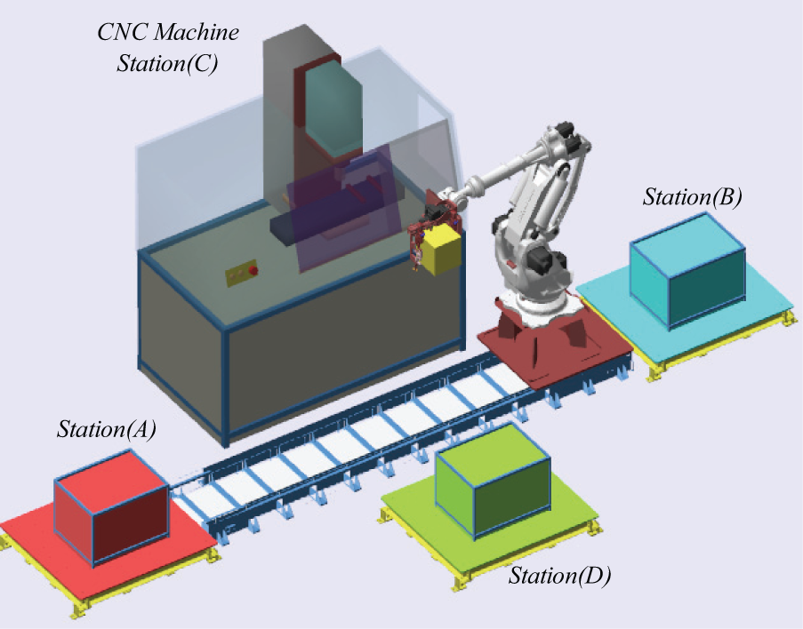
A robot cell.
As shown in Figure 5, we can identify four tasks of the robot: (T1) moving a part from A to C, (T2) moving a part from B to C, (T3) moving a part from C to D, and (T4) return to the home position. The task table of the robot can be constructed very easily, as shown in Figure 6. For each task Ti, we can define input/output symbols (O_Ti, I_Ti) of a PLC and constraints on the execution sequence of tasks. The task table, shown in Figure 6, can be converted into a device template model as follows.
Device template model of the robot
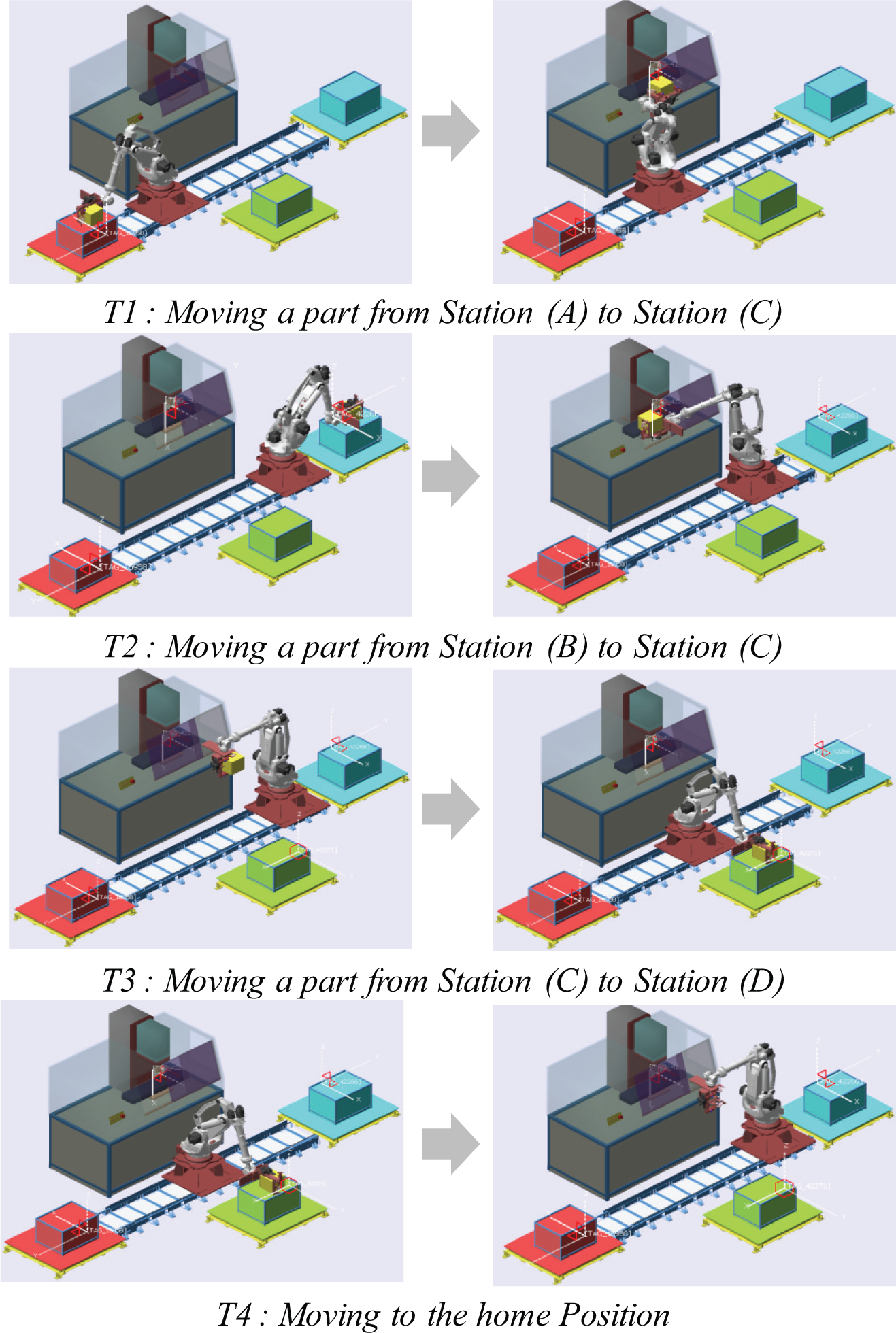
Tasks of the robot.
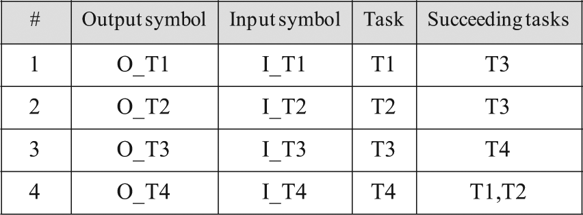
Task table of the robot.
Virtual commissioning of the robotic cell.
As mentioned in the previous sections, a device template model (consisting of three sets and one function) can generate an atomic model (consisting of three sets and four functions) of a device for the virtual commissioning of a PLC. By using the proposed conversion algorithm, we can generate a DEVS atomic model for the robot as follows.
Virtual device model of the robot:
Start_T3, Done_T3, Start_T4, Done_T4,}
In this way, we can extract atomic models (behavioral models) of virtual devices. Once the atomic models are constructed, a virtual plant model can be easily defined using a coupled model that combines all the atomic models. The constructed virtual plant model enables virtual commissioning to validate control programs prior to real implementation. There are various PLC vendors in the market. They provide hardware PLCs as well as PLC emulators. For hardware PLCs, it is possible to communicate using the open connectivity (OPC) technology (http://www.opcfoundation.org/) that provides OPC in industrial automation. In case of PLC emulators, communication can be done by using the component object model (COM) technology (http://www.microsoft.com/COM/) that enables software components to communicate.
Discussion and conclusion
The ultimate goal of virtual commissioning is to provide a virtual plant for an automation engineer to validate their control logic prior to its real implementation. As a result, we can achieve the seamless transition from the virtual to the real environment. However, a major drawback of virtual commissioning is the excessive amount of time required for the construction of a precise virtual plant model consisting of multiple virtual device models. Conventionally, the atomic model of the DEVS formalism has been used to represent the behavior of a virtual device. Modeling using DEVS formalism, however, requires in-depth knowledge of modeling and simulation.
All automated manufacturing devices interact with the input/output symbols of a controller. While output symbols trigger tasks in manufacturing devices, input symbols are used to capture the present status of the devices through sensors. To relieve the difficulties of model construction, we provide a device template model including tasks, input/output symbols, and constraints on the execution sequence of tasks. The construction of a device template is very intuitive to engineers who lack in-depth knowledge of modeling and simulation. Once the device template model is constructed, it can be used to generate the complete behavior model (an atomic model) of the device. The generation algorithm of an atomic model is developed and demonstrated for a robotic cell. The generated atomic model of a virtual device acts as an interface while communicating with the PLC programs.
Footnotes
Declaration of conflicting interests
The authors declare that there is no conflict of interest.
Funding
This work was partially supported by the Agency for Defense Development (UD120035JD and UD110006MD) and Korea Association of Industry, Academy and Research Institute (C0003579). Also, the research was partially supported by the National Research Foundation grant (2010-0021040) funded by the Ministry of Education, Science and Technology, Korea.