
Abstract
Function combination designs integrate multiple product functions into a single product carrier. In this article, we proposed a function combination design method based on the functional redundancy analysis of parent products for the conceptual design process. According to the design task, we analyzed each parent product function carrier, established an expression model of functional elements based on the functional basis approach, and constructed a functional structure of the parent product based on relationships among energy, material, and signal flow. Then, we established a product function redundancy matrix and carrier redundancy matrix, and obtained redundancy functions and the principle structure carrier. We constructed a function carrier matrix for function combination products, sought the appropriate principle, established a design structure matrix, analyzed the coupling relationship between the principle scheme and structure carrier, and obtained a conceptual scheme of combination products through operations including reuse, variant, removal, and increase. Moreover, we used a sticker removal machine as an example to verify the validity of our function combination method.
Keywords
Introduction
Product function combination design involves a variety of parent products in the same or different fields of use, with similar or different functions as a combination object. These products are analyzed for commonality among functional structures, and some or all functions are assigned to a new structure, thereby solving for a design approach that can integrate multiple functions on a new product. This type of design can meet customer demand for multi-functional products, is adaptive as opposed to creating an entire new design (Beitz and Pahl, 1992), and can significantly reduce the design effort. It also improves design efficiency and reduces cost and development risks.
Scholars carried out extensive research on product function combination design. Chen (1997) proposed that function combination was the combination and integration of multiple functions into one product to meet diversity demands of various target markets and users, and explored the design principle of functional integration. Conversely, Cao et al. (2012) proposed that function combination was a process of combination and optimization in accordance with a certain relationship of functional elements with combination properties based on functional requirements, and the functions should be combined in accordance with the classification of functions and functional relationships. Singh et al. (2007) illustrated the importance of multi-functional product design methods using real-life examples. Malatesta et al. (2015) proposed a method for a preliminary validation of new configurations at the marketing stage. These studies focused on the concept and criteria of function combination design, and although product design case studies emphasized the importance of function combination design methods, specific design methods were not proposed. Wang (2001) proposed the reuse theory for minor modification of existing product parts for use in new products. Duhovnik et al. (2001) developed an n-T looping methodology for the whole development process of new products, which covered goal setting, conceptual design, process planning, manufacture and assembly, and so on. Hu et al. (2012) proposed the fuzzy reconfigurable design theory of complex mechanical product design according to user functional requirements and emphasizing reuse of existing product components. Zheng et al. (2017) proposed a system framework in support of one-of a-kind product conceptual design process in a cloud-based design (CBD) environment. Reconfigurable design can provide innovative design space by fully reusing design knowledge and resources. Prasad (2001) established a concept for product, process, and methodology systematization to handle both structural complexity and computational complexity in the new product realization. Lewis and Kalyanasundaram (2011) identified shared functions and components of two products by establishing a function share matrix and component share matrix according to the reconfigurable principle, and combined functional structures of parent products to obtain a new product. The key of this kind of research was reconfigurable product design. Through reconstruction design on two or more single-functional product structures, they generated multi-functional product solutions, and focused on solving the product reconfiguration problem. The main objective of the above studies is to reuse parent product components, but they neither selectively combine parent product’s functions, nor study how to best use product function carriers. Lin (2008) used fuzzy clustering method to explore the possibility of function integration among different products, and through case studies, explored several typical approaches suitable for function integration innovation from function combination, functions balance, functions synergy, and other design point of view. Wu et al. (2013) used the function analysis system technique (FAST) to sort product functions according to their primary and secondary relationships, examined interdependencies between the functions, and then combined the functions. Kang and Tang (2013) studied a matrix-based conceptual scheme solution, used functional models, a functional similarity matrix, a functional element matrix, and an element association matrix to realize new multifunctional product design by discarding, retaining, or modifying elements. Li et al. (2009) established a functional structure and analyzed contradictions of functional principles based on functional product integration and innovation, and applied the TRIZ theory (theory of the resolution of invention-related tasks) to generate problem solutions. Liu et al. (2014) and Fu et al. (2014) proposed model product integration approaches for product innovation based on function combination and TRIZ. Furthermore, Fu et al. (2013) built a function-oriented new product integration and innovation design model through a combination of axiomatic design and TRIZ theory. Borgianni and Dominik (2015) and Chechurin and Borgianni (2016) put attentions on the sources that manifest skepticism with respect to the combination of axiomatic design and TRIZ. Prasad (2016) developed a simple icon-based flowcharting methodology for capturing concurrency of tasks and activities during product design and development phase, and the methodology can be used to construct the functional structure of product. These studies primarily used combinations of fuzzy clustering methods, TRIZ theory, axiomatic design, functional analysis system technology methods, and matrix methods as design tools to solve functional contradictions appearing in function combination design. Methods for discovering function conflicts and handling structure repulsion were not explored. In another direction, Liu et al. (2016) proposed a multi-mode product structure design, established a multi-mode module using structure sharing in different modes of partial module structure, and achieved multi-mode switching product operation. Li et al. (2016) introduced a function module partition approach for conceptual design of complex product through community detection using weighted and directed complex networks. However, this shared structure could only operate in one mode at a time.
In conclusion, existing studies proposed some ideas about product function combination and using existing design methods to assist product functions. However, the following issues require further study: (1) remove function redundancy and carrier redundancy, (2) create variant designs of function extension, carrier distribution, and function carriers, and (3) establish a set of complete systematic design methods for function combination.
In this article, we proposed a product function combination approach for conceptual design based on product functional structure and a design structure matrix (DSM). We aimed to find and solve function redundancy and carrier redundancy issues among parent products to be combined, make reasonable allocation among functions and carriers, and generate a conceptual scheme of combination products through carrier variation design. The remainder of this article is organized as follows: Section “Design process and implementation” focuses on our product function combination method implementation based on functional redundancy analysis, section “Design example” presents a sticker removal machine as an example to validate our function combination design method, and section “Conclusion” presents our conclusions and ideas for future studies.
Design process and implementation
Design process
Product function combination design is divided into three stages. In the first stage, according to the design task, multiple parent product structures are analyzed, functional elements are abstracted, and functional configurations are generated. In the second phase, functional redundancy and carrier redundancy between parent products are analyzed. Then, finally, in the third stage, new product functions and function carriers are rationally allocated, and a conceptual combination product design model is solved.
Analysis of parent product functions
Product function combination design integrates functions of existing multiple parent products into a new product. Therefore, we must first analyze parent product structures and generate the functional structures before determining what function redundancies possibly exist among the parent products.
The parent products are selected based on the functional requirement. The performance functions are acquired through analyzing design specification, and then the functions are decomposed to required functions (which must be achieved in the designed product) and expected functions (which can be considered in the designed product). Considering the requirement of required functions, the parent products are selected. If there are multiple parent products, the expected functions are considered in the selection of parent products.
We disassemble parent products into function carriers and abstracted detailed functional elements from function carriers (Figure 1). Functional elements are expressed as “verb+noun.” For example, cell function is expressed as “store energy” and “supply power.” We use verbs and nouns from standard vocabulary in functional basis (Stone and Wood, 2000) and according to the functional vocabulary expansion provided by literatures (Hirtz et al., 2002; Hubka and Eder, 2001; Szykman and Racz, 2001).
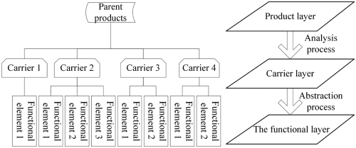
Parent product analysis.
Definition 1—function carrier. This is the physical structure for achieving product functions or sub-functions. For example, the function carrier of thermos liners achieves two functions: maintaining internal temperature and secure storage of contents.
A new or modified design establishing functional structure is a major step in the design process. Product functional structure show connections between functional elements and provide evidence for functional redundancy analysis.
The steps for creating a parent product functional structure are as follows:
Establishment of a functional white box
Since function combination design is re-designed by combining existing products, the product functional system is known. In this article, we refer to this as a functional white box. Energy flow is indicated by solid lines, material stream represented by broken lines, and signal flow indicated by dotted lines.
Functional decomposition
The traditional functional decomposition method (Beitz and Pahl, 1992) is greatly affected by the designer experience and personal preference, and therefore, the same decomposition method might yield different results for different designers. This article presents a new decomposition method, which was based on three kinds of flow: energy, material, and signal flow. We conducted functional decomposition on parent products, subdivided main flow, and summarized functional elements operating on flows. The functional tree generated by this method showed correspondence between functions and flows to facilitate subsequent establishment of functional structures.
Construct function chain and generate functional structure of parent product
According to the logic between flow sequence and the function of flow, and starting from the function tree, we arranged functional elements and established a function chain. There were four basic types of function chains: the tandem function chain refers to the ordered arrangement of functional elements, and the output of the former function element is the input of the later functional element; the parallel function chain refers to the various functional elements working in parallel that have a common input or output; the recursive function chain refers to functional elements forming a feedback loop; and the Diego union-style function chain, in which each element has its own action, obtains its final output from the outputs of various functional elements.
Construction of functional structure of parent product
Using the parent product analysis method in Figure 1, the parent product is decomposed into multiple carriers with multiple functional elements, and the relations among these carriers are acquired. The functional chains of functional elements in every carrier are constructed, and then, the total functional structure of parent product is constructed through connecting these functional chains of carriers using their relationship in parent product analysis.
Analysis of function redundancy among parent products
This section addresses function redundancy analysis among products. In product function combination design, there must be function redundancy and carrier redundancy among multiple parent products, namely, the same, similar, or repulsive capabilities. Redundancy has two meanings: (1) having extra unnecessary portions, hereinafter referred to as passive redundancy; (2) copying some part, or adding duplicate portions to enhance security, hereinafter referred to as active redundancy. In this study, we focused on reducing passive redundancy.
Our steps in function redundancy analysis are as follows:
Establish functional redundancy matrix
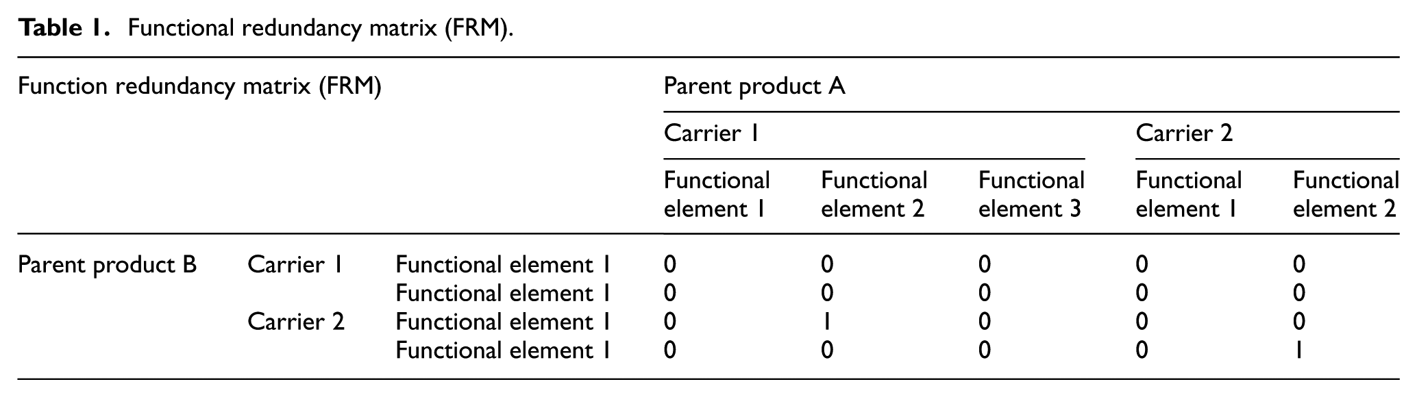
Definition 2—functional redundancy matrix (FRM). Functional elements of different parent products as matrix row and column elements. Matrix cells represent connections among corresponding rank elements. By analyzing interactions among rank elements, we found redundancy among functional elements of different parent products to facilitate subsequent processing.
FR represents the redundancy among functions in FRM. Its size is (0-1), FR = 1 indicates a fully redundant state, FR = 0 indicates no redundancy status, and FR = 0-1 shows a partially redundant state (Table 1).
Functional redundancy matrix (FRM).
The following four aspects are the basis for determining redundancy degree:
Description of functional elements. D represents the degree of similarity described by functional elements, and its size is (0-1). Examples include separate, divide, fence out, and remove.
Input flow of functional elements. Compare similarity degrees of the three kinds of flow of input functional elements. The similarity degree is represented by I, and its size is (0-1).
Output flow of functional elements. Compare similarity degrees of the three kinds of flow output from functional elements. The similarity degree is represented by O, and its size is (0-1).
Function carrier corresponding to functional elements. The similarity degree is represented by C, and its size is (0-1). For example, the corresponding function carrier to start power is a switch.
Redundancy is determined according to the weights of these four aspects:
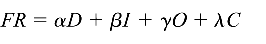
where α, β, γ, and λ are the corresponding weights of the four aspects, and α+β+γ+λ = 1. Hereinafter, all corresponding weights are averaged.
Functional redundancy analysis
Redundancy value analysis and treatment among different functional elements of parent products was conducted on three main cases. (1) When FR = 1, the product functional element was fully redundant. The redundant functional element was removed because for a plurality of same functionality, only one must be kept. (2) When FR = 0, the product functional elements had no redundancy. All functional elements were preserved, but no other operations. (3) When 0 < FR < 1, the product functional elements had partial redundancy. In this case, we partially combined redundant functional elements into a new functional element, not only to meet the functional requirements, but also to reduce the number of functional elements. At the same time, the appropriate carrier was also changed (see the carrier processing method described in the next section). If the functional elements could not be combined, this process followed the method in step 2.
Establish a carrier redundancy matrix
Definition 3—carrier redundancy matrix (CRM). Function carriers of different parent products as row and column elements in a matrix. Matrix cells represent connections of ranked elements. By analyzing rank element interactions, we found redundancy among carriers of different parent products to facilitate subsequent processing.
CR represents redundancy among carriers in the CRM, its size is (−1, 0), CR = 1 indicates a fully redundant state, CR = 0 indicates an irrelevant state, and CR = −1 shows a repulsive state (Table 2).
Carrier redundancy matrix (CRM).
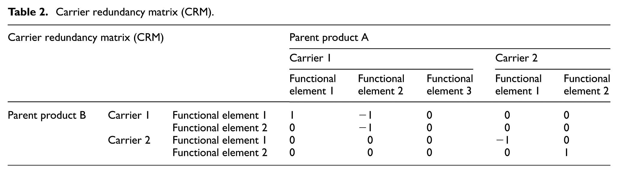
Function carrier relationships of parent products have the following four conditions. (1) If carriers and carrying functional elements are the same, “1” is filled in the corresponding matrix position. (2) If carriers are the same but carrying functional elements are different, “−1” is filled in the corresponding matrix position. (3) If carriers are different but carrying functional elements are the same, “−1” is filled in the corresponding matrix position. (4) If both carriers and carrying functional elements are different, “0” is filled in the corresponding matrix position.
Analyzing and processing methods of redundancy value among function carriers of different parent products was conducted for three main cases. (1) When CR = 1, the product function carriers were fully redundant. Redundant carriers were removed and only one of the multiple carriers with the same functionality was kept. (2) When CR = 0, the product function carriers had no redundancy. In this case, the carrier was kept and no further action was required. (3) When CR = −1, product function carriers were repulsive to each other. In situations with different carriers and same carrying functional elements, same functional elements and their corresponding carriers were deleted based on the functional redundancy processing method. In situations with same carriers but different carrying functional elements, we transformed the carrier and integrated a plurality of functional elements into it to realize its full use.
Carrier transformation
Operations for removing and retaining carriers are relatively easy, with focus and difficulty on how to design the transformation of carriers. Our four operating methods of carrier transformation are summarized as follows:
Size ratio variations. Through enlarging or reducing the carrier size ratio, the corresponding suitable structure was obtained and requirements for structural dimensions in product structure design were met.
Position variations. By changing carrier positions, the space was re-allocated to eliminate repulsion among carriers in spatial positions and position requirements were met.
Morphological appearance variations. Morphological changes can be endless under circumstance that ensures no functionality change, and therefore, morphological appearance modification was used to meet requirements in some special cases.
Carrier assembly variations. Using a combination of carrier variation methods, we organically combined multiple carriers, thereby reducing the total number of function carriers and simplifying carrier processing and assembly.
In engineering design, relevant carrier variations often require the integrated use of these four methods.
Solving for a new product conceptual model
According to the aforementioned redundancy analysis result, we conducted functional combination of multiple products to generate a conceptual model of new product. Based on desired requirements in the design task requirement table and full use of carriers, we either borrowed the original carrier function or added a few new carriers to extend functionality of the new product. Finally, to meet customer expectations and requirements, the number of new carriers and product cost were reduced as much as possible.
Function and carrier configuration
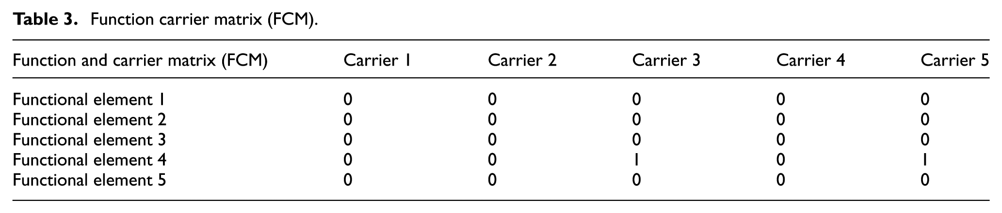
Appropriate carrier selection and configuration is the key step in design. In accordance with the function and carrier redundancy analysis results, a function carrier matrix (FCM) was established to conduct function and carrier configuration.
Definition 4—FCM. Functional elements and carrier required for combination design as matrix column and row elements. Matrix cells represent connections among ranked elements. Through element interactions, we analyzed and obtained the carrier required by the functional elements, and completed function and carrier configuration.
In the FCM, “1” indicates that the carrier was involved in functional element achievement, while “0” means the carrier was unrelated to the functional element achievement (Table 3).
Function carrier matrix (FCM).
Solving for the conceptual mode
Establish DSM
The DSM (Liu, 2009) is ranked elements with the same order forming a square, with non-diagonal cells showing connections among corresponding ranked elements. The carrier in FCM was taken as rank elements in DSM to determine the connections among ranked elements and connection directivity. To obtain more detailed information about the connections among ranked elements, we divided these connections into four categories: space connection, energy connection, material connection, and signal connection. The relation among these carriers is acquired from the constructed functional structure of parent product in section “Analysis of parent product functions.” The element in the DSM is determined using the following rules:
Space connection. If there are connection (dependency, containment, orientation, etc.) between the two carriers, such as the carrier A is located at the front of carrier B, or the carrier A is located inside carrier B, the element of space connection is 1, else the element is 0.
Energy connection. If there are energy transmissions, transformation between the two carriers, the element of energy connection is 1, else the element is 0.
Material connection. If there are material transmissions, transformation between the two carriers, the element of material connection is 1, else the element is 0.
Signal connection: If there are signal transformations between the two carriers, the element of material connection is 1, else the element is 0.
After analyzing all connection values between carriers, the DSM which represents the connections between carriers is established, which is shown in Figure 2.
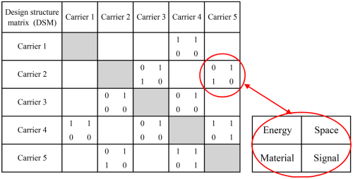
Design structure matrix.
Conceptual model for solving
DSM spatial connection data were analyzed to obtain all positional relationships among carriers and form a new product preliminary conceptual model. Furthermore, the energy, material, and signal connection data were analyzed to determine which connections the carriers relied on, and how to connect them to meet the connection in the matrix and also meet corresponding process requirements.
By repeatedly checking spatial position arrangements of function carriers and connections among carriers, the product preliminary conceptual model is optimize using fuzzy evaluation method (Zhang et al., 2014), and then, the satisfactory final conceptual model was realized.
Design example
Establish a parent product functional structure
We designed a new advertising sticker removal machine. According to task requirements, we combined two kinds of parent product functions: a pump type water gun (Figure 3(a)) and an electric screwdriver (Figure 3(b)). We then conducted functional combination design.

Parent products for function combination design: (a) pump-type water gun and (b) electric screwdriver.
We constructed functional element structures of the two parent products. Next, we established a functional white box, and determined the input and output flow. Then, we expanded functional decomposition based on energy, material, and signal connections, as shown in Figures 4 and 5. According to the functional decomposition tree, we aggregated function chains to form functional structures of each parent product, as shown in Figures 6 and 7.
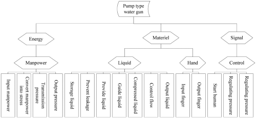
Functional decomposition tree of pump-type water gun.
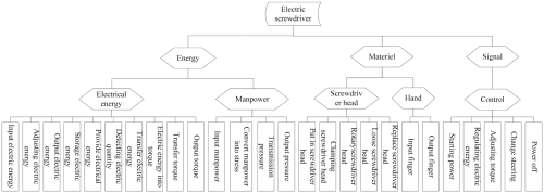
Functional decomposition tree of electric screwdriver.
Function chains A and B of electric screwdriver.
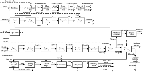
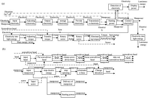
Functional structure of electric screwdriver.
Redundancy analysis in parent products
We established an FRM among parent products, determined the redundancy value among functional elements, and filled in the matrix cell (Table 4). In the FRM,
Functional redundancy matrix (FRM).
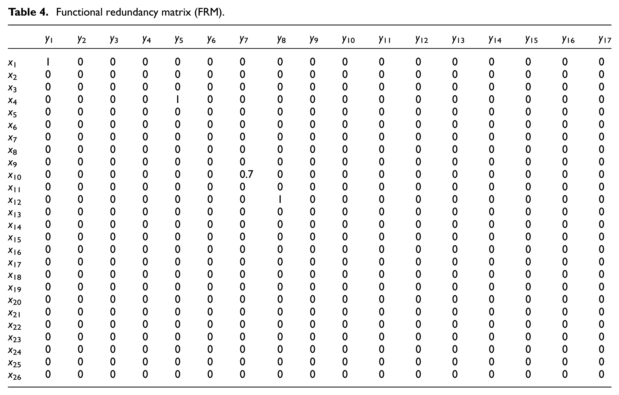
We then conducted actual usage analysis. Advertising stickers were present in conspicuous locations, and the lighting function was not required; therefore, it was removed. Different from tightening and loosening screws, removing the stickers do not need reversing, therefore, we removed the changing steering function.
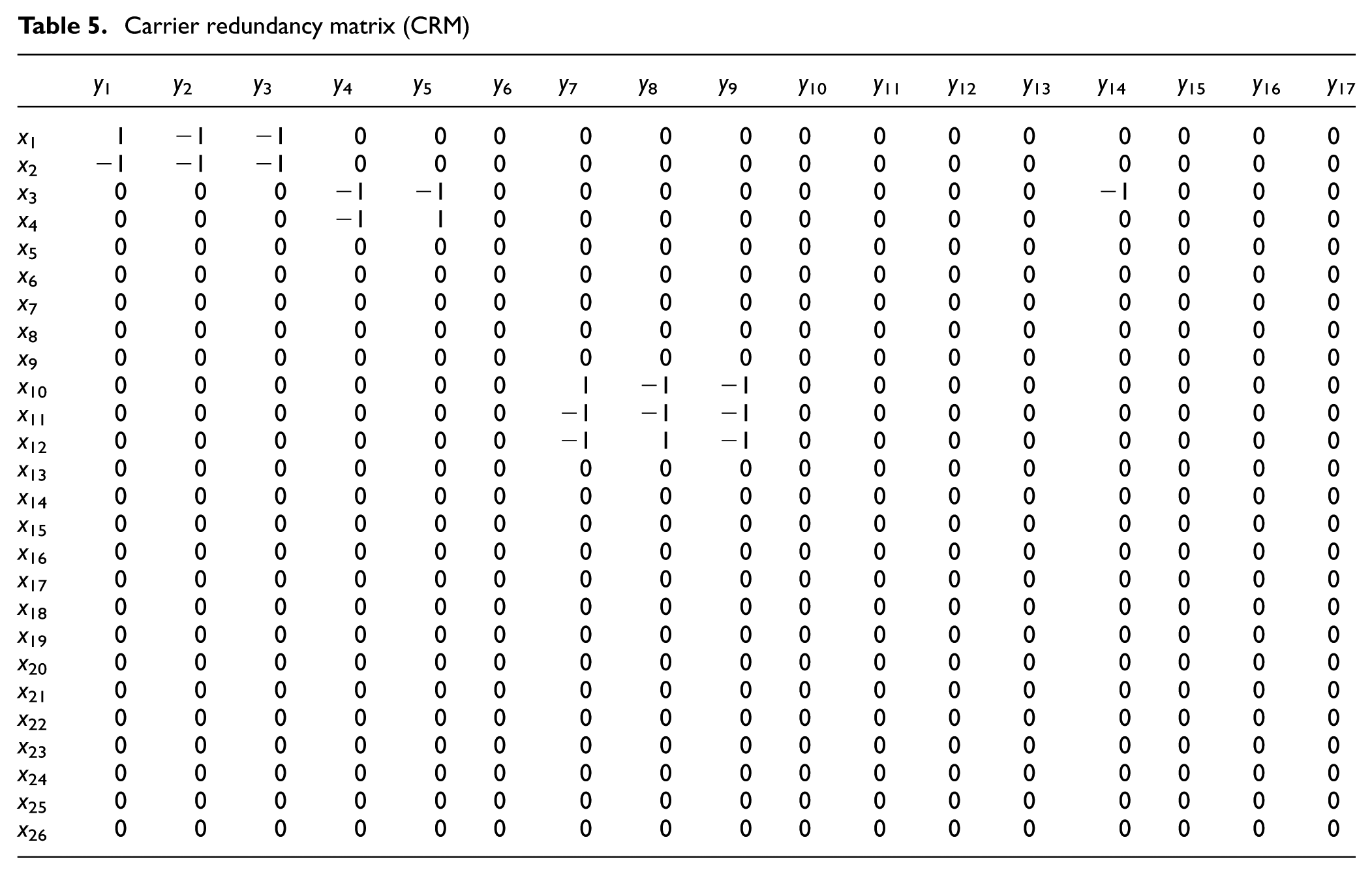
Next, we established a CRM based on the carriers of parent products, determined the redundancy value among carriers, and filled in the matrix, as shown in Table 5. Since the outer casing had redundancy and repulsion among functional elements, we only kept one outer casing. Meanwhile, we conducted variation design on the outer casing, which was no longer used for storing liquids, and instead used an external storage kettle for easy filling of cleaning fluid. The water plug could also be removed, and therefore, the entire outer casing did not need to be sealed. Not sealing the casing sets aside cooling holes to help motor cooling. Handles showed redundancy and repulsion among functional elements, so we only kept one handle. Since we used an external storage kettle to store liquid, the handle was used to only store the battery. The switch also had redundancy and repulsion among functional elements. We only kept one switch, and conducted variation design it. The switch was designed as two separate bodies, with separate functions for regulating water and power. Finally, since the functions of the direction switch and LED lights were removed, these carriers were deleted.
Carrier redundancy matrix (CRM)
Solving for a new product conceptual model
Function extension
We combined the battery and handle, creating a removable battery handle, which greatly increased battery capacity and improved utilization of the carrier. The original product holder held the batch head, but we changed that to hold the rubbing head. The clamp and release functions allow for different types of cleaning rubbing heads to be used in different situations. To be flexible to user needs, we also increased the functions of the cleaning blade. By designing it on the outer casing, the blade can be folded and easily replace.
Functions and carrier configuration
We established an FCM through the interactions among ranked elements, and analyzed it to obtain the function carriers required by functional elements, as shown in Table 6.
Function carrier matrix (FCM).
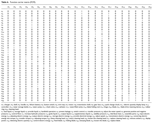
m1: charger; m2: shell; m3: handle; m4: lithium battery; m5: button switch; m6: wire way; m7: motor; m8: transmission shaft; m9: gear box; m10: quick change chuck; m11: electric quantity display lamp; m12: controller; m13: water storage kettle; m14: water pump; m15: check valve; m16: catheter; m17: water-filled cavity; m18: blade folding rod; m19: hinge; m20: blade; m21: blade drive retaining device; m22: rubber ring; m23: cleaning head.
n1: load liquid; n2: storage liquid; n3: provide liquid; n4: handheld operation; n5: prevent leakage; n6: switch control; n7: transfer pressure; n8: adjust the water speed; n9: generate positive and negative pressure; n10: control flow; n11: increase hydraulic pressure; n12: guide liquid; n13: output liquid; n14: supplementary liquid; n15: stability pressure; n16: distribute heat; n17: assemble parts; n18: input electric energy; n19: adjusting electric energy; n20: output electric energy; n21: storage electric energy; n22: provide electrical energy; n23: adjust speed; n24: transmission electric energy; n25: converting electric energy into torque; n26: transfer torque; n27: adjusting torque; n28: clamp cleaning head; n29: rotary cleaning head; n30: loosen the cleaning head; n31: replace cleaning head; n32: remove stickers; n33: display power; n34: detecting electric quantity; n35: control electric energy; n36: fixed blade; n37: folding blade; n38: clamping blade; n39: loosen the blade; n40: replace blade.
Solving for conceptual model
We established a DSM to determine the connections among various ranked elements and their directivity, as shown in Figure 8.

Design structure matrix.
According to DSM data, we then conducted a spatial location arrangement of function carriers and connections among carriers as follows:
Space and energy connections were between the charger and battery. The charger was independent from the product design, and since the battery could be removed and replaced, the charger charged replacement batteries separately via wires. This eliminated delayed product use.
The outer casing had spatial association with many carriers such as the handle, switch, motor, wires, gear box, battery indicator light, and circuit board. The outer casing must position and secure other carriers, and thus, we reserved spaces for other carriers in design.
The battery was connected to the button switch, motor, battery indicator lights, and circuit board via wires.
The button switch was mounted on the outer casing. A sub-button was connected to the battery and motor, and controlled motor rotation and stopping by starting or stopping power. Another sub-button was connected to the water pump to control pressure.
The motor was secured to the outer casing, received power from the battery, and passed rotational kinetic energy through the transmission shaft via a gearbox to the rubbing head.
The holder was fixed to the turning shaft, and clamped and released the rubbing head. It also transferred torque energy to the rubbing head.
The battery indicator light was exposed by the reserved hole on the outer casing. It connected to the battery, circuit board, and switch via wires, and displayed the remaining battery charge when in use.
The storage kettle was screwed on the outer casing via a screw thread and with a rubber ring to prevent leaking water. The kettle passed water to the water cavity through a conduit and one-way valve.
The pump was connected to the button switch on one side, with the other side connected to the water cavity. It passed pressure through a one-way valve and conduit to spray water, and relied on negative pressure to suck water from the reservoir kettle into the cavity.
The one-way valve was between the conduit and water cavity, and controlled fluid flow using water pressure signals.
The blade was connected to the blade holder, which was connected to the folding lever. The folding lever was fixed to the outer casing via a hinge. Energy was transferred through these parts.
The rubbing head was mounted on the rubbing head holder and received rotational energy passed by the holder.
We repeatedly checked the spatial location arrangement of function carriers and connections among carriers to optimize and improve the conceptual model of the sticker removal machine (Figure 9).
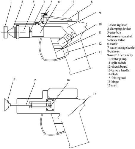
Conceptual model of sticker removal machine.
Conclusion
In this article, we proposed a product function combination method for conceptual design based on product functional structure and a design matrix. First, we abstracted functional elements by analyzing known products, created product functional structures based on decomposition of three types of flows. Then, we combined the FRM, CRM, FCM, DSM, and other methods to obtain a function combination conceptual design model. We used a pump-type water gun and an electric screwdriver as an example to generate a conceptual design model of sticker removal machine. This was realized by analyzing connections between functions, carriers, and between functions and carriers, and using operations such as increasing, removing, and merging functionality, or removal, increase, reuse, and variation of carriers. This example illustrated that our proposed method of function combination design helps with rapid and effective multiple parent product function combination, and thereby improves design efficiency and accuracy. Follow-up research will focus on the weights of the four aspects involved in parent product functional redundancy analysis, and product conceptual scheme integration after function combination.
Footnotes
Declaration of conflicting interests
The author(s) declared no potential conflicts of interest with respect to the research, authorship, and/or publication of this article.
Funding
The author(s) disclosed receipt of the following financial support for the research, authorship, and/or publication of this article: This research work was supported by the National Natural Science Foundation of China (51375451, U1610112, and 51505421).