
Abstract
INTRODUCTION
Use of the combined aiming guide (Synthes, Paoli, PA) in foot and ankle surgery has been described before. 1 The complex three-dimensional anatomy and relatively small size of the bones of the midfoot necessitates precise screw placement in fixation of this area of the foot. Subsequently, cannulated screw systems have become popular for fixation in the midfoot. Although they aid in accurate screw placement, these screw systems carry unique risks. 2 Cannulated screws have reduced relative strength; thus, increased diameter or expensive alloys are used to compensate for the inherent geometrical weakness.
The authors routinely use noncannulated 3.5-mm screws in fixation of fractures, dislocations, and arthrodeses of the midfoot. Utilizing solid 3.5-mm screws maximizes strength while maintaining a small diameter screw and keeping cost of fixation low. Without a cannulated system, there is risk of loss of screw hole position or orientation. This can be frustrating and can risk losing reduction after drilling. To accomplish reproducible and accurate screw placement, we routinely use an aiming device in a unique fashion when placing 3.5-mm compression screws in the midfoot (Figs. 1 and 2).
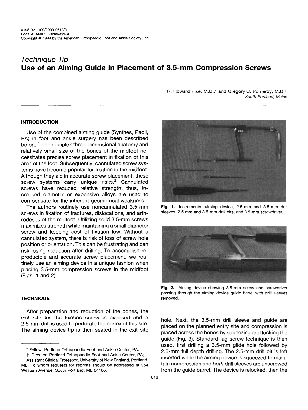
Instruments: aiming device, 2.5-mm and 3.5-mm drill sleeves, 2.5-mm and 3.5-mm drill bits, and 3.5-mm screwdriver.
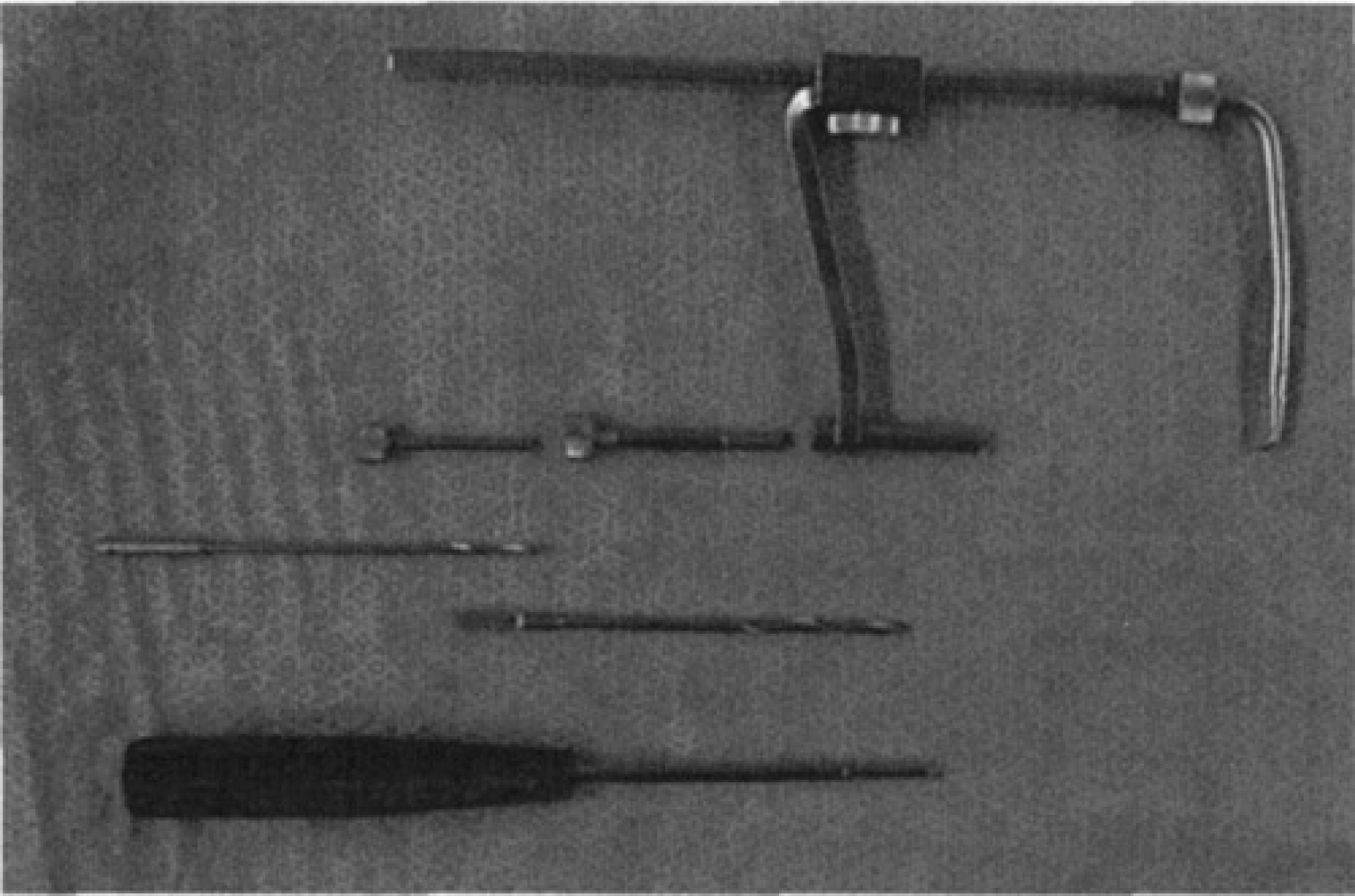
Aiming device showing 3.5-mm screw and screwdriver passing through the aiming device guide barrel with drill sleeves removed.
TECHNIQUE
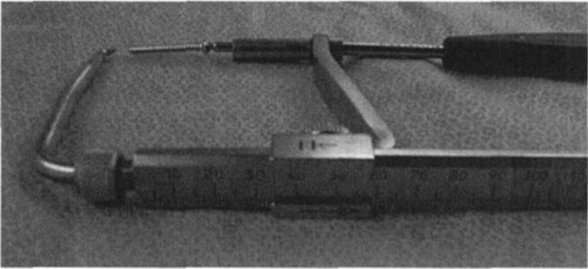
After preparation and reduction of the bones, the exit site for the fixation screw is exposed and a 2.5-mm drill is used to perforate the cortex at this site. The aiming device tip is then seated in the exit site hole. Next, the 3.5-mm drill sleeve and guide are placed on the planned entry site and compression is placed across the bones by squeezing and locking the guide (Fig. 3). Standard lag screw technique is then used, first drilling a 3.5-mm glide hole followed by 2.5-mm full depth drilling. The 2.5-mm drill bit is left inserted while the aiming device is squeezed to maintain compression and both drill sleeves are unscrewed from the guide barrel. The device is relocked, then the drill bit and sleeves are completely removed (Fig. 4). The screw is then inserted through the guide barrel. The aiming device is removed just before final tightening of the screw (Fig. 5). This allows the screw to engage the distal cortex previously occupied by the tip of the aiming device.
Drill and sleeves.
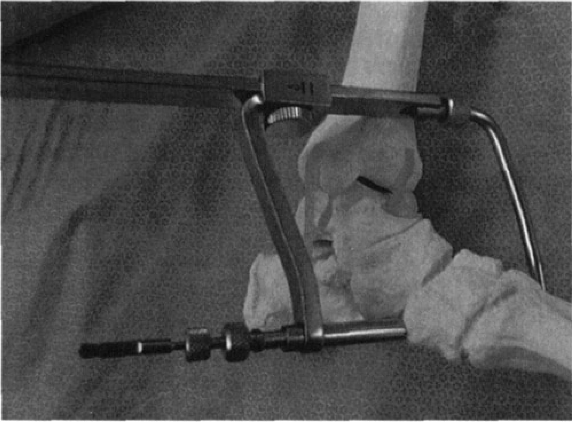
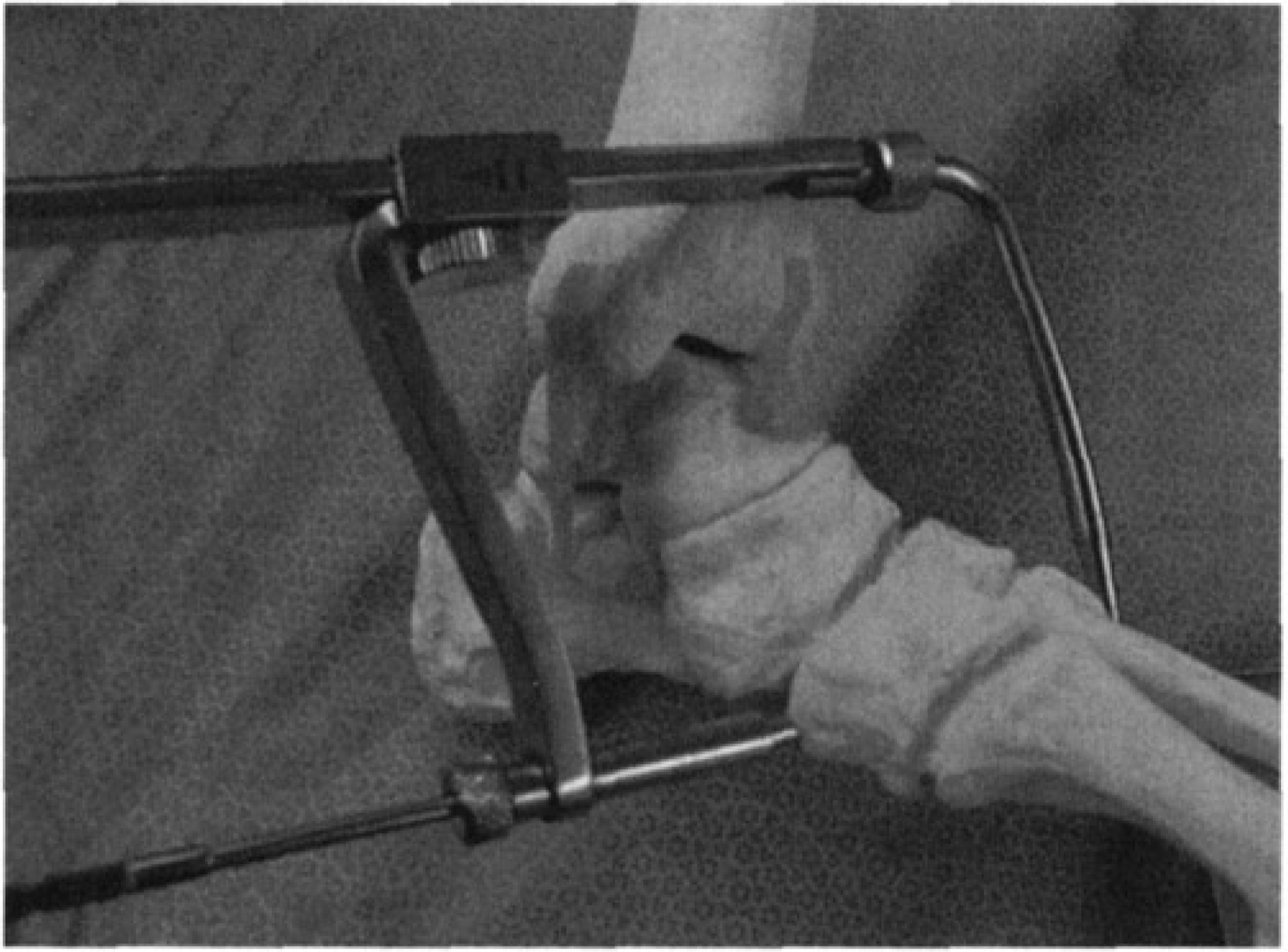
After drilling, the drill sleeves are loosened and the aiming device guide barrel is advanced to bone.
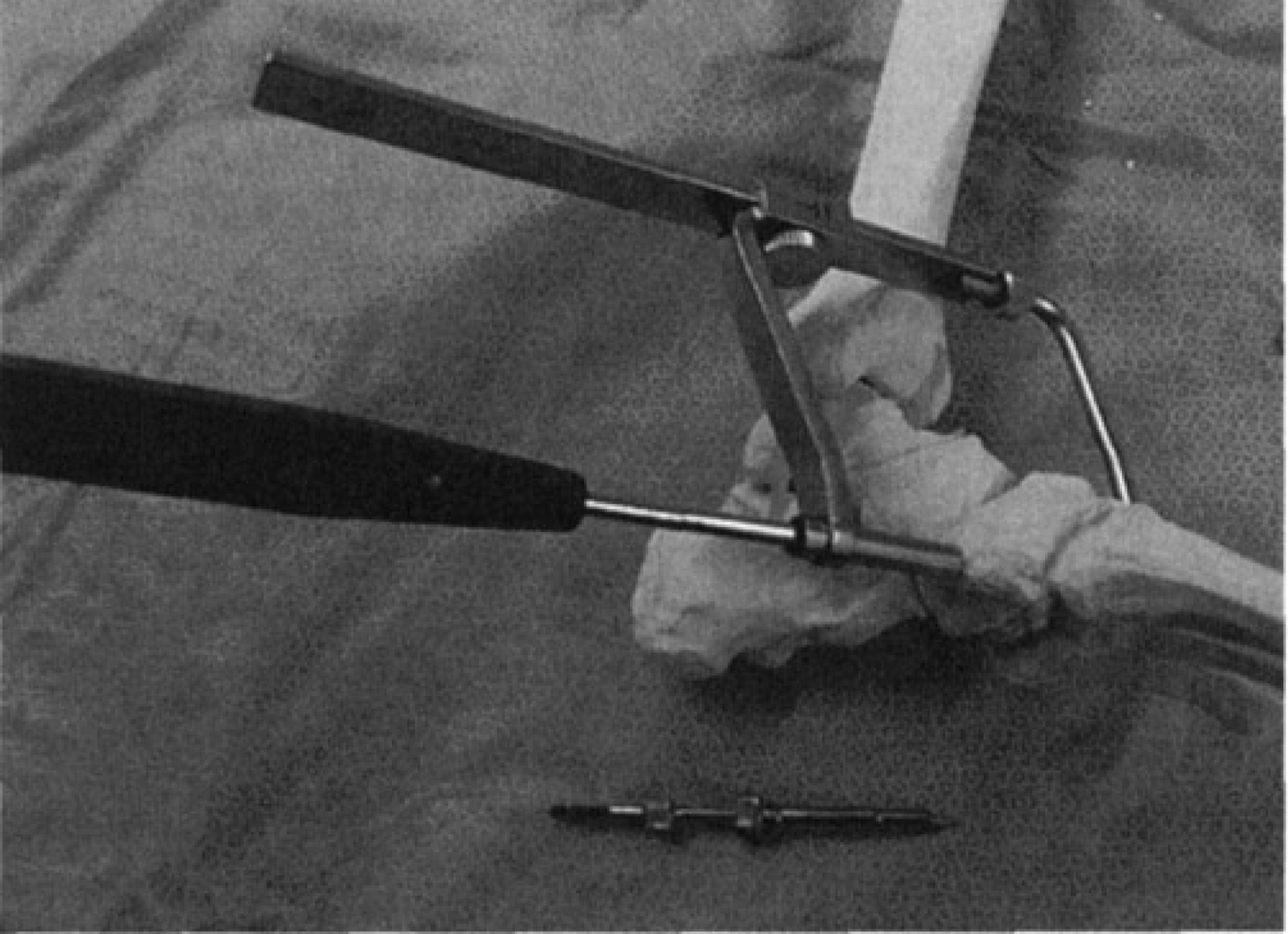
Screw placement through aiming device guide barrel after removal of 2.5-mm drill and drill sleeves.