
Abstract
Passivity-based control of under-actuated mechanical systems with nonlinear friction effects in the generalized coordinates of motion is analyzed in this paper. Nonlinear friction is modeled with a modified LuGre dynamic friction model. The internal states of the dynamic friction model are incorporated as generalized coordinates in a port-controlled Hamiltonian formulation for the complete mechanical system in such a way that all passivity properties of this formulation are preserved for the extended generalized coordinates system. Interconnection and damping assignment passivity-based control laws are developed for the models of two case studies: a building with a magneto-rheological damper and a double pendulum. Simulation results are also presented.
Keywords
1. Introduction
Control of under-actuated nonlinear mechanical systems is a challenging task. This is especially true when nonlinear friction plays a significant role in describing the dynamics of the system. Dynamic friction models, such as the popular LuGre model (Canudas et al. 1995), were introduced to allow the representation of important nonlinear friction phenomena such as hysteresis, viscous and Coulomb friction and the Stribbeck effect in the context of dynamics systems. They have been successfully used to develop model-based friction compensation control schemes.
On the other hand, port-controlled Hamiltonian equations (PCHEs) of dynamic systems has lead to the development of interconnection and damping assignment passivity-based control (IDA-PBC), a control design methodology that takes advantage of the natural energy interconnections and dissipation properties of dynamic systems (Ortega et al. 1999; Ortega et al. 2002b; Ortega and García-Canseco 2004) and that allows a systematic design of control laws. IDA-PBC shapes the energy of the system, by modifying the internal energy structure of interconnection and dissipation. IDA-PBC has proven to be effective in solving control problems for under-actuated mechanical systems (Gómez-Estern et al. 2001; Ortega et al. 2002a; Gómez-Estern et al. 2004; Acosta et al. 2004).
Analysis of the LuGre model under a passivity point of view has been undertaken in Barabanov and Ortega (2000), where authors proved that the map from relative velocity to force is passive if and only if some relation between some of the LuGre model parameters holds. Koopman et al. (2008) presented a new analysis of the passivity of the LuGre model that extends the findings to Barabanov and Ortega (2000). This analysis requires a nonstandard representation of the PCHE, different from the standard representation adopted in this paper.
The passivity analysis of the LuGre model attempted in Barabanov and Ortega (2000) focused on the friction model itself, looking at the relative velocity–force map. It does not take into account the possible coupling effects of this model internal variables with the generalized coordinates of the dynamic model. In this paper, a different approach to model nonlinear dynamic friction models in the context of PCHEs is attempted. It is shown that in order to incorporate the LuGre friction model into systems posed in standard PCHEs, a modification to this model is required. Once the change is introduced, the resulting dynamic system expressed in PCHEs, with the generalized coordinates extended with the internal states of the dynamic friction model, it is possible to prove that the new description preserves the passivity properties of the port-controlled Hamiltonian (PCH) description with a proper choice of the output of the system.
Once the new friction description is introduced, IDA-PBC control methodology is applied to two case studies. The first is a building that incorporates a magneto-rheological damper (MRD) as actuator. This system is open-loop stable and the goal of the damper is to reduce the amplitude of the horizontal displacements of the building stories when it is subjected to a strong seismic excitation. A control law is derived for one MRD placed between the basement and the first floor of the structure that allows important reductions in the amplitude of the stories displacements, velocities and accelerations. The second case study is a double pendulum actuated in the first link. In this case a semi-global control law, based on IDA-PBC, is presented that allows us to solve, simultaneously, the swinging up and stabilization of a double pendulum with nonlinear friction effects in the joints of the two links. Simulation results again show the ability of the IDA-PBC control law to stabilize the double pendulum in the uprising, open-loop-unstable position.
In this paper we focus on the application of the IDA-PBC design methodology, together with a proper description of the dynamic friction phenomena in PCHEs for the two case studies. The goal is to show the benefits of exploiting the structural information contained in this Hamiltonian formulation to design control laws that deal with under-actuated systems with nonlinear dynamic friction phenomena included.
This paper is organized as follows. Section 2 introduces the PCHEs for mechanical systems, while Section 3 describes the modified dynamic friction model. Section 4 discusses the incorporation of this modified model in the PCHEs framework to represent nonlinear dynamic friction effects. Section 5 summarizes the IDA-PBC methodology design and recalls the necessary conditions required to design a control law. Section 6 illustrates the design of the IDA-PBC control law for a building with a MRD, including simulation results. Section 7 illustrates the design of the IDA-PBC control law for the under-actuated double pendulum and the simulation results obtained. Section 8 contains the concluding remarks and directions for future work.
2. Port-controlled Hamiltonian equation
PCHEs provide a modeling framework for representing lumped parameter physical dynamic systems. The state space is a smooth manifold composed by flow and effort variables, whose inner product results in power units. These variables define two power ports that allow energy interchange between the system and its environment. In PCHE, systems have a smooth function, the Hamiltonian, and are endowed with a geometric structure, called the Dirac structure. The Hamiltonian represents the total energy in the system and the Dirac structure explicitly unveils the power-preserving interconnections and the power-dissipation properties of the system in terms of the gradient of the Hamiltonian (Secchi Cristian and Fantuzzi 2007).
PCHEs have the important property that the interconnection in feedback of two PCH systems preserves this structure (Sepulchre et al. 1997). To design a control law that exploits this property based on a passivity approach, the IDA-PBC control design methodology was developed. IDA-PBC allows us to simplify the closed-loop stability analysis of the system–controller pair and to shape the energy interconnection and dissipation structure of the resultant system to achieve regulation goals (Ortega et al. 1999; Ortega et al. 2002b; Ortega and García-Canseco 2004).
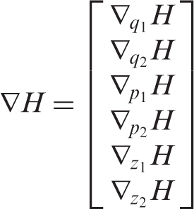
The state of a mechanical system in PCHE is written in terms of generalized position coordinates qT = [q1,…, q n ]T and generalized momenta coordinates pT = [p1,…, p n ]T.
Hamilton's canonical equations, for systems with no external generalized forces, are

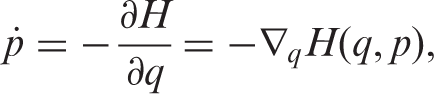
Hamilton's canonical equations can be transformed into PCHEs, that provide a structure where it is easy to observe energy interchange and dissipation in the system and to connect it to external power ports. A general form for a system in PCHE is (Van der Schaft 1999)

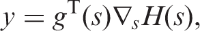
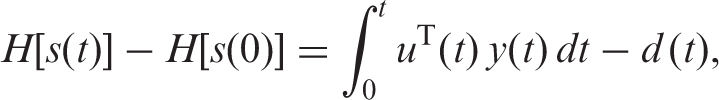
The system in Equation (1) is passive from u to y as it satisfies the energy balance equation (Ortega et al. 2001)
3. Friction model
The friction phenomenon is present in mechanical systems when two contact surfaces suffer a relative displacement. Friction considerably modifies the dynamics of systems and, if not properly taken into account, has important consequences in the cost of operation and maintenance (Armstrong-Helouvry 1991). Friction phenomena representation in dynamic systems is difficult due to the highly nonlinear nature of stiction, stick–slip, hysteresis, Stribeck effect, etc. (Rabinowicz 1995). Friction models can be classified in several ways: according to the number of parameters required, the number of variables used, the number of different phenomena that they represent, the easiness of simulation, the passivity properties, etc. Although there is a good number of friction models available, this paper focuses in three important dynamic friction models: Dahl, Haessig and Friedland, and LuGre models.
Dahl's model (Dahl 1976) is a first-order dynamical model of friction, where the state variable is the friction force, that is able to represent both Coulomb friction and hysteresis. Another decisive friction model, in the perspective of this paper, was introduced by Haessing and Friedland (1991) that hypothesized that the contact zone between two bodies can be described by bristles that act like springs with a level of stiffness related to each surface hardness. Relative motion of the surfaces induce deformation and, eventually, slip of the bristles. Finally, the LuGre model (Canudas et al. 1995) incorporates elements of Dahl's model and the bristles model, and proposes a first-order dynamical model with an internal state that represents the average deflection of bristles in the contact zone of the bodies. This model also allows us to represent Coulomb friction, hysteresis and the so-called Stribeck effect that explains the transition from static friction to Coulomb friction.
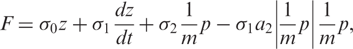
The model of friction used in this paper is a modification of the LuGre model and has the form

Rewriting Equation (2) in matrix form makes it easier to observe the passivity structure of this model
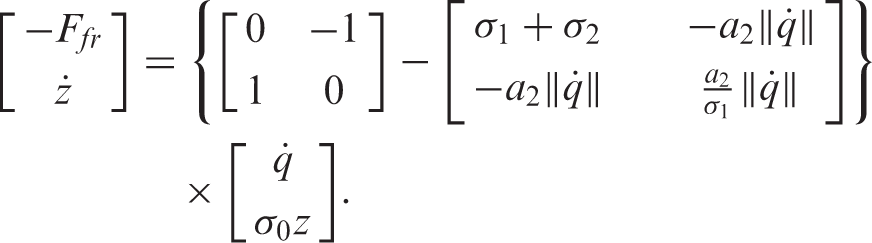
The two changes in Equation (2) with respect to the model introduced in Canudas et al. (1995) are a new term that depends on the square of the relative velocity, that appears both in the dynamic and force equations, and the absence of the term describing the Stribeck effect. This modification also allows to find conditions on the dynamic friction model parameters, similar to those found by Barabanov and Ortega (2000), that yield a passive map from the velocity
The typical LuGre model structure cannot be used directly with the IDA-PBC design methodology. On the other hand, as is verified in Barabanov and Ortega (2000), the LuGre model is a passive map from force to velocity. The reasoning behind the proposed modifications to the LuGre model was to find out what conditions were required for this model to fit in a Hamiltonian framework whose main characteristic is to represent passive dynamic systems, such as a passive friction model.
The verification of the ability of the model to reproduce friction behavior was empirical. For that purpose, velocity and force data obtained from experiments with a MRD were used (Jiménez and Alvarez-Icaza 2005). Results of these experiments are shown in Section 6.
4. Dynamic friction model in port-controlled Hamiltonian equations
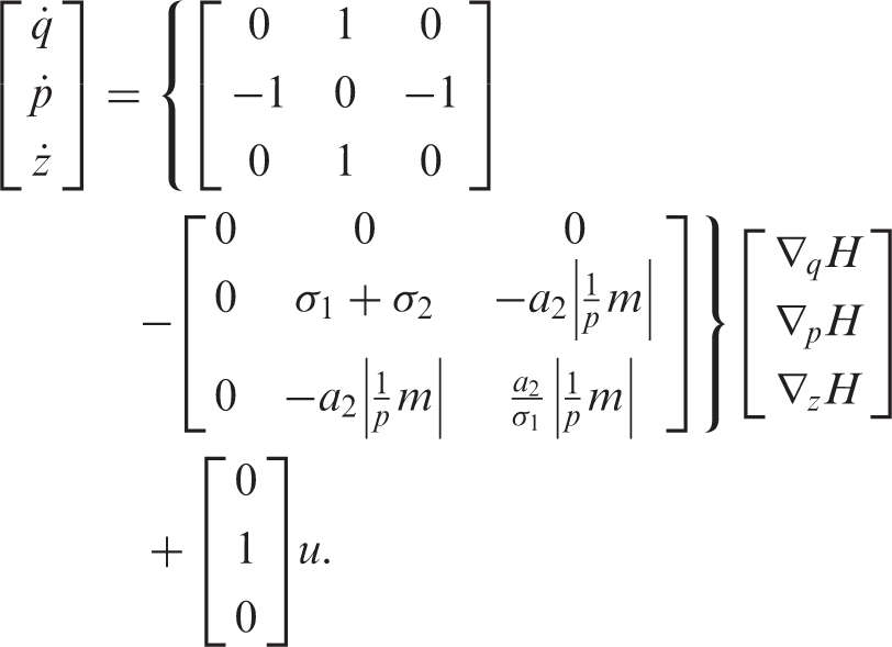
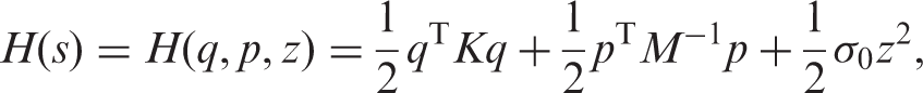
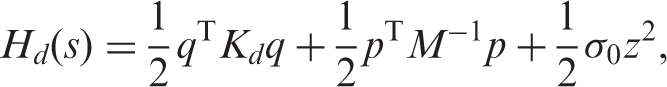
To illustrate the effect of including the LuGre model in a system described by PCHEs consider the simple case of a mass m attached to a spring with stiffness k, subject to a friction force F and a control force u. In this case the three generalized coordinates are the position (q), the momentum of the mass (p) and the internal state of the friction model (z). The Hamiltonian of the system is

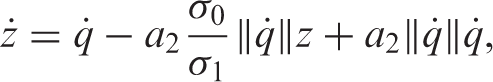
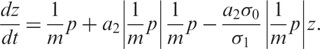
Expressing the LuGre model in these generalized coordinates,
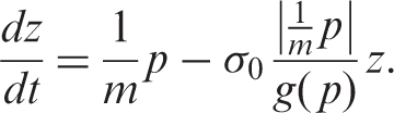
The dynamics of the system is given by
It should be noted that Equation (7) is not in PCHE form as the dissipation matrix is not symmetric.
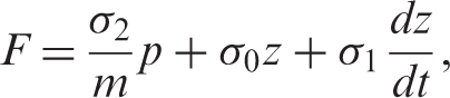
On the other hand, the model for the force from Equation (2) in these generalized coordinates is
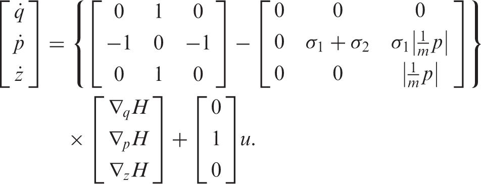
Writing the dynamics for the systems in this case yields
5. IDA-PBC methodology
According to Ortega et al. (2002b), to design a IDA-PBC control law, the first step is to propose a desired behavior for the closed-loop system, that expressed in PCHEs is

If J d (s) = J(s) + J a (s) and R d (s) = R(s) + R a (s), then the following proposition, from Ortega et al. (2002b), provides the conditions that the control law and the desired behavior have to satisfy in order to guarantee the stability of the desired equilibrium point. If these conditions are satisfied, the control law is such that the closed-loop system will satisfy Equation (11).
Proposition 1
Given J(s), R(s), H(s), g(s) and the desired closed-loop equilibrium point, s* ∈ R
n
, assume that functions β(s), J
a
(s), R
a
(s) and vector ϰ(s) can be found to satisfy
Structure preservation. The desired closed-loop systems preserves PCHE structure. Integrability. ϰ(s) is the gradient of a scalar function. Equilibrium setting: ϰ(s*) = −∇
s
H(s*)
Lyapunov stability:
Then, the control law u = β(s) yields the closed-loop system in Equation (11), with energy storage function


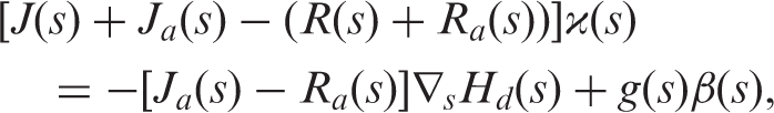
One possible way to find the control law, as suggested by Ortega et al. (2002b), is to propose functions J
a
(s), and R
a
(s) and find H
a
(s) as the solution to the matching condition
6. IDA-PBC of a civil structure
In this section IDA-PBC is applied to a building equipped with an MRD, as illustrated in Figure 1. The goal is to design a control law that reduces the stories displacements during an earthquake. In Figure 1, m
i
is the ith story mass, c
i
and k
i
are the viscous damping and the stiffness coefficients between i and i − 1 stories, Building with n stories.
In the dynamic model in Equation (18), the force in the MRD will be expressed with a similar model of the MRD model introduced in Jiménez and Alvarez-Icaza (2005). This MRD model is modified to follow the structure suggested in Equation (2). Accordingly, the state is extended to include z, the internal state for the MRD LuGre-based model. The model for the MRD damper, adapted from Jiménez and Alvarez-Icaza (2005), is

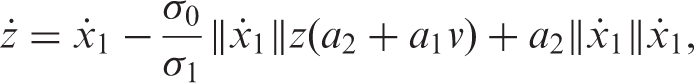
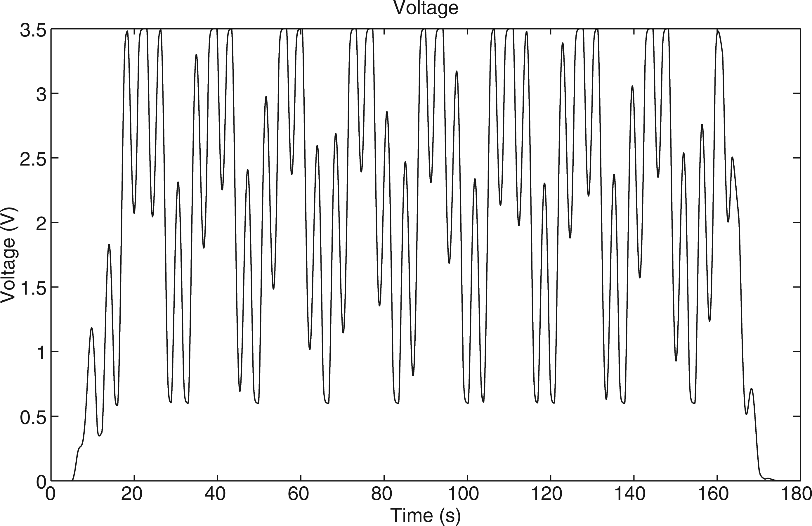
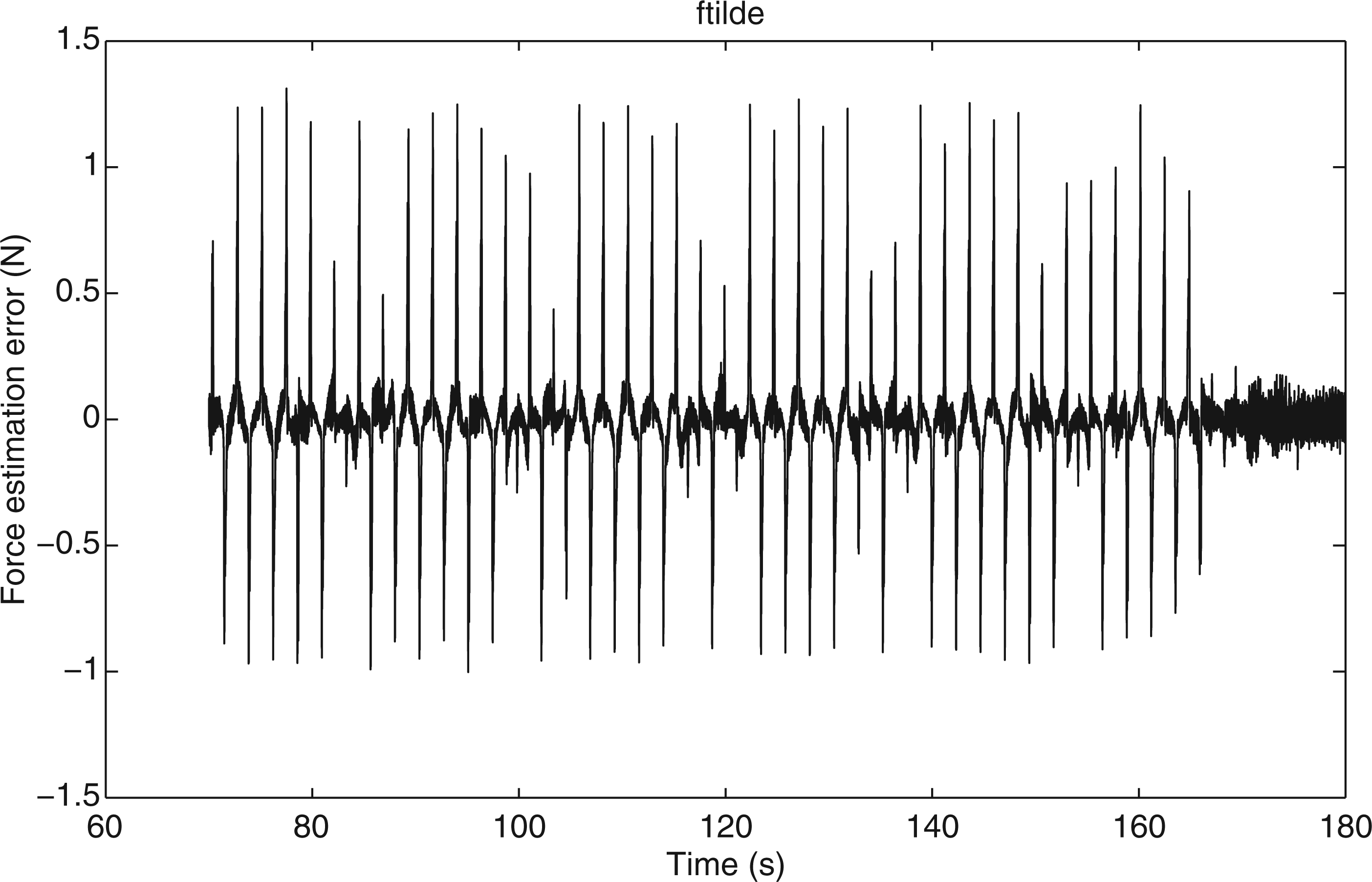
To test the performance of the model presented in Equations (19) experiments were performed with a MRD. Figures 2 and 3 show one example of the velocity and voltage that were used to excite the damper. The velocity has sinusoidal shape and the voltage is a combination of several sinusoidal functions. During the experiments a load cell was used to measure the force at the damper and the force data was collected. Using a standard least squares recursive algorithm, identification of the parameters for the model in Equations (19) was attempted. Figures 3 and 4 show the obtained results. In Figure 4 both the measured and the estimated force are plotted and Figure 5 shows the force estimation error. As can be appreciated, the fit of the model to experimental data is very good and confirms the ability of the model in Equations (19) to represent the friction behavior of the MRD. More details about the experimental set-up can be found in Jiménez and Alvarez-Icaza (2005). It is convenient to remark that the model in Equations (19) is a generalization of the model in Equations (2), that can be recovered from Equations (19) if the voltage is fixed.
Relative velocity of the ends of the MRD. Voltage applied to the MRD. Measured and estimated force at the MRD using the model in Equations (19). Force estimation error between the measured and estimated force at the MRD using the model in Equations (19).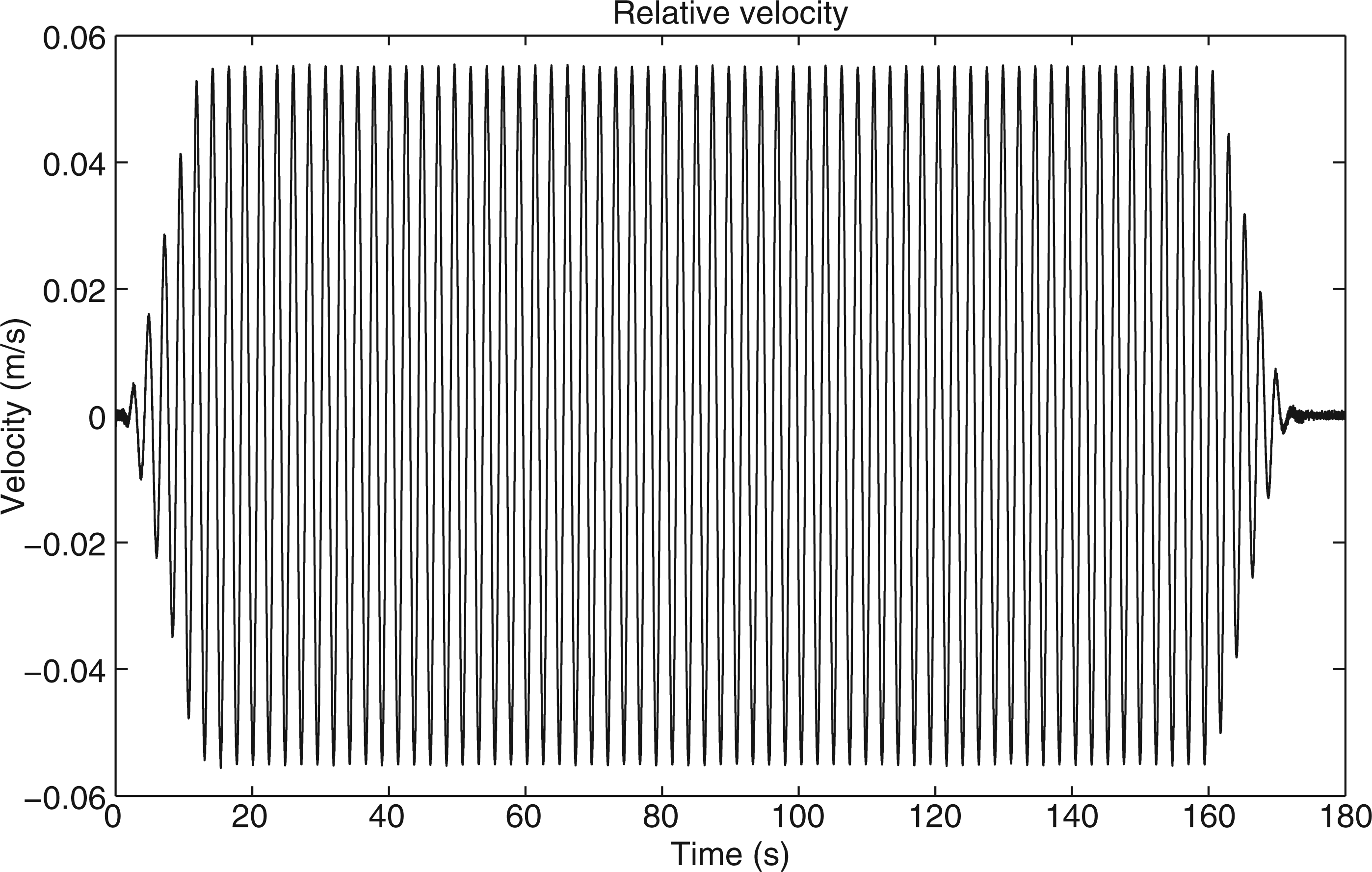
The following energy storage function is proposed
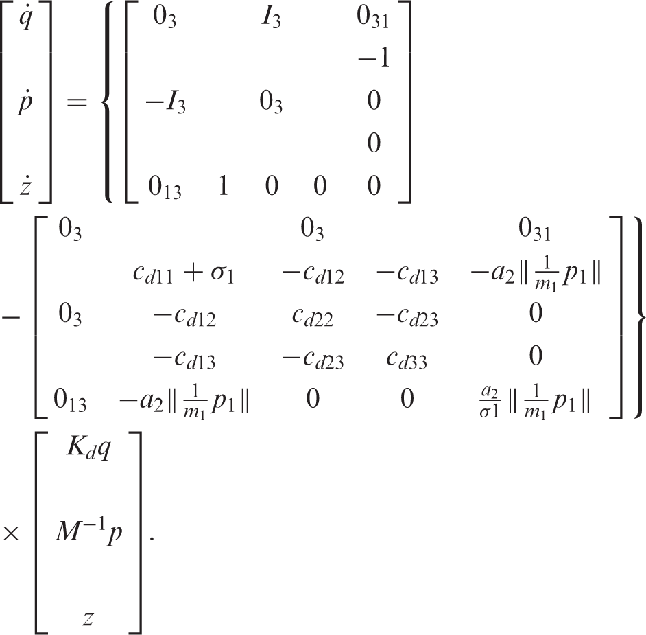
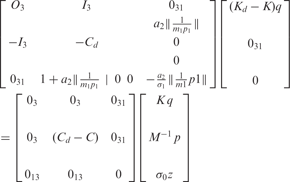
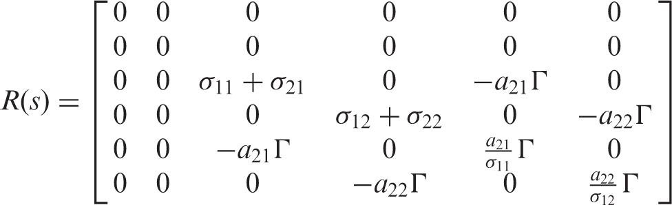
The building–MRD model in PCHE is given by
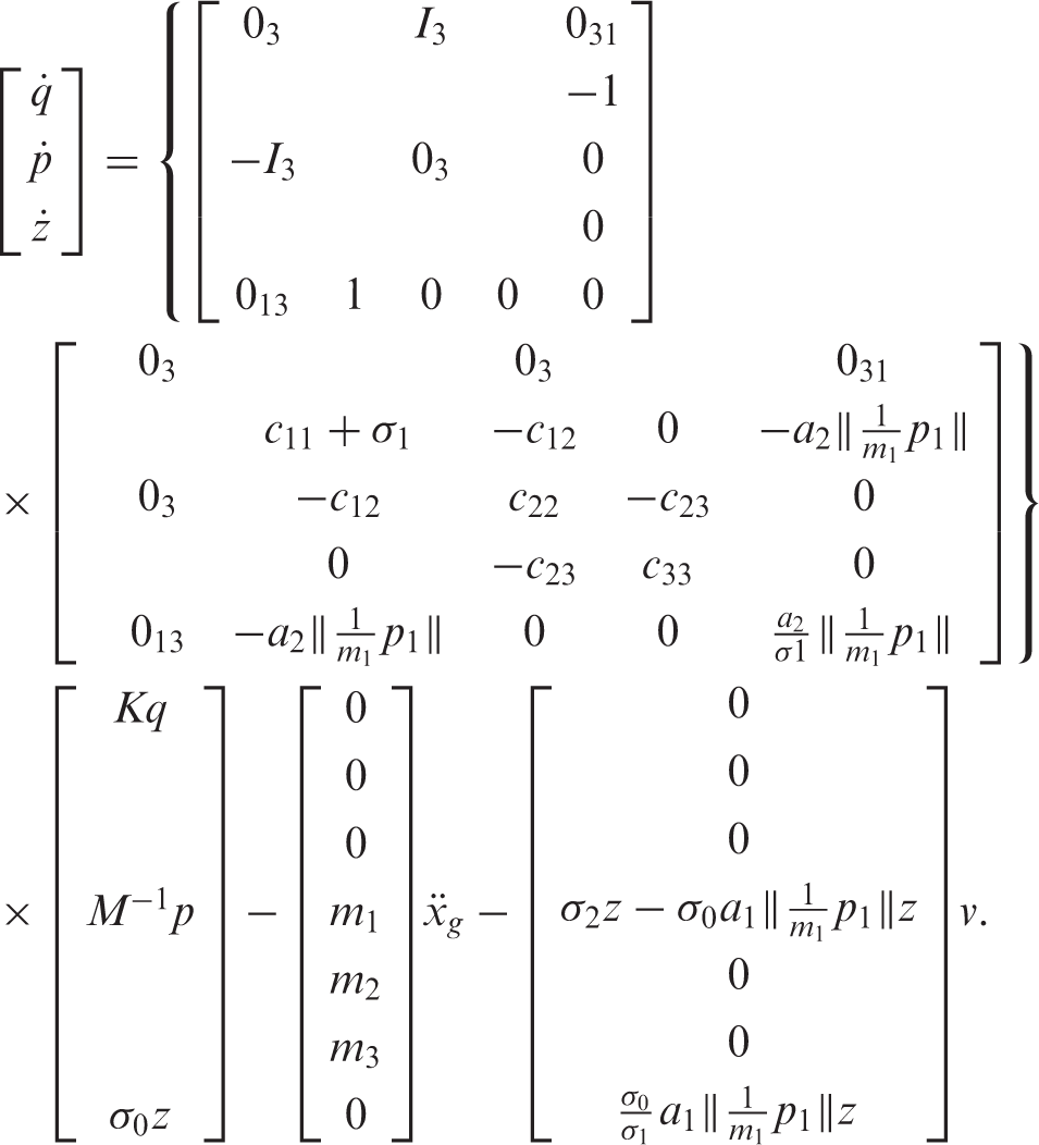
In Equation (21) J(s) = −J(s)T and R(s) = R(s)T ≥ 0, because C = CT ≥ 0 and a2/σ1 ≥ 0. 3
Note that elements (4, 7) and (7, 4) in the J(s) of matrix in Equation (21) are induced by the new terms included in the modified friction LuGre model of Equations (2). The same happens with elements (4, 7) and (7, 4) of matrix R(s) of the same equation. If the LuGre model is not modified in the suggested manner, the skew-symmetry of matrix J(s) and symmetry of matrix R(s) would not longer hold when the PCHE state is extended with the internal state z.
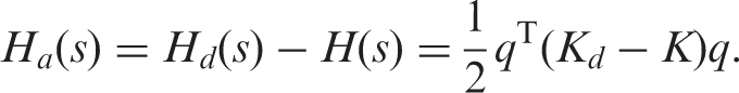
As the first step to design the control law, the following desired energy function is proposed
Comparing Equation (21) and Equation (24), it can be noted that the interconnection matrix has no changes and that the damping matrix is modified. It is also convenient to remark the inclusion of element cd13 in matrix C d , that is not present in the original matrix C and that couples, by the control law, the motion of the first and third stories. A similar coupling can be produced by introducing an element kd13 in the desired stiffness matrix K d . 4 Introducing this coupling into the desired behavior is important for this kind of under-actuated systems and underlines the advantages of the PCB-IDA control methodology.
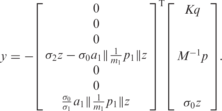
The assigned energy function is, according to Equation (13),
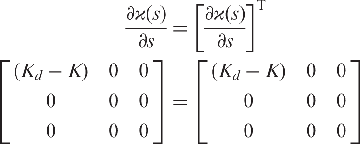
Structure preservation:
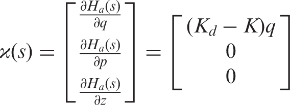
Integrability. If Equation (14) is solved, ϰ(s) satisfies
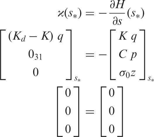
Equilibrium assignment. Here ϰ(s) evaluated at s* satisfies
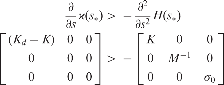
Lyapunov stability. The Jacobian of ϰ(s) at s* satisfies the bound


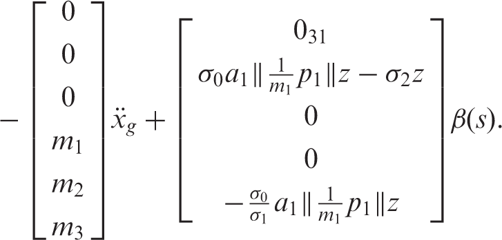
To calculate the control law, Equation (12) is solved
For the numerical simulation, the three-story building presented in Dyke et al. (1998) is used. The seismic excitation is taken from the ground acceleration in Mexico City's 19 September 1985 earthquake, recorded at ‘Secretaría de Comunicaciones y Transportes’
5
(North–south component), that is shown in Figure 6.
Ground acceleration during the 19 September 1985 Mexico City earthquake (SCT-NS).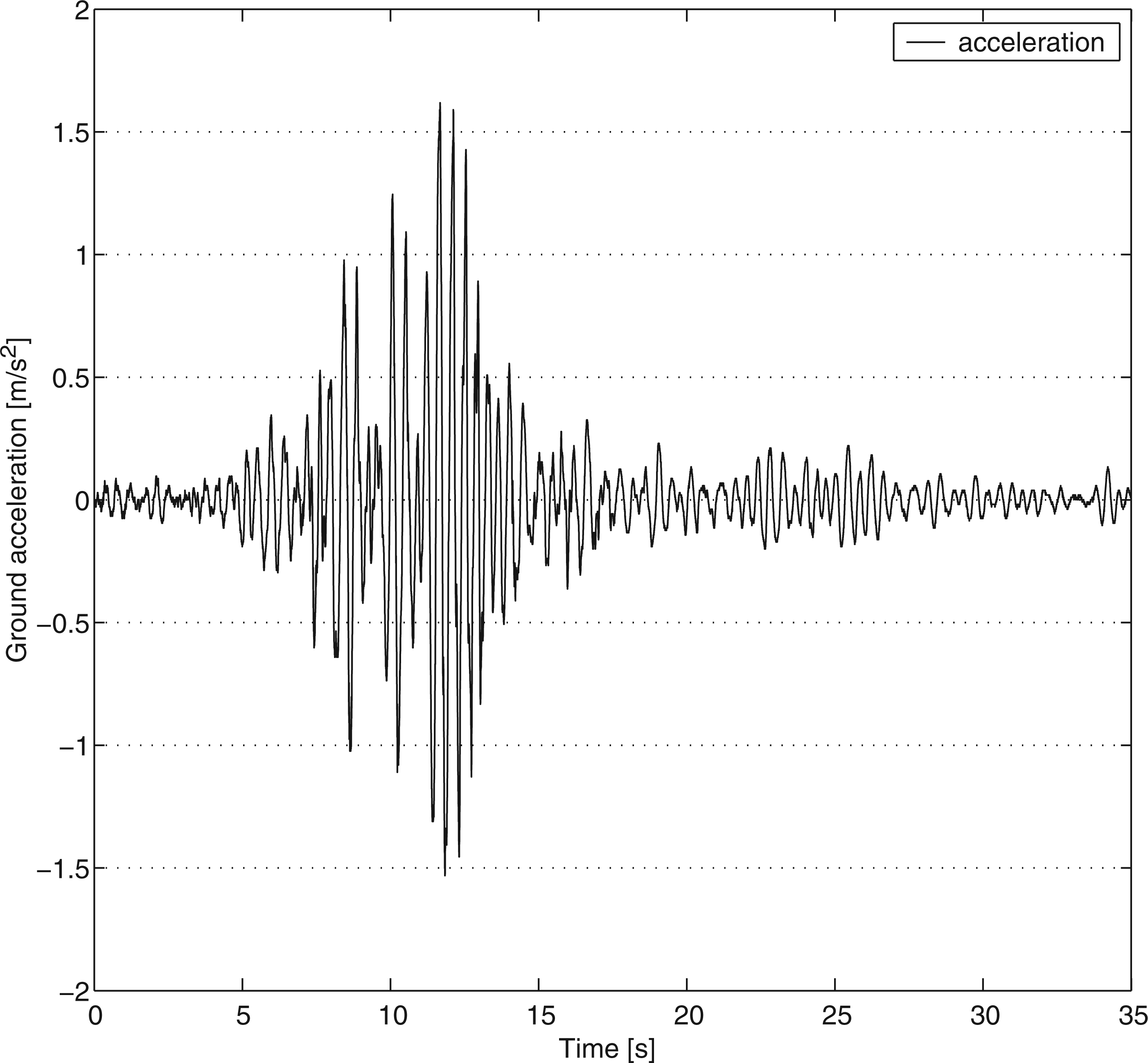
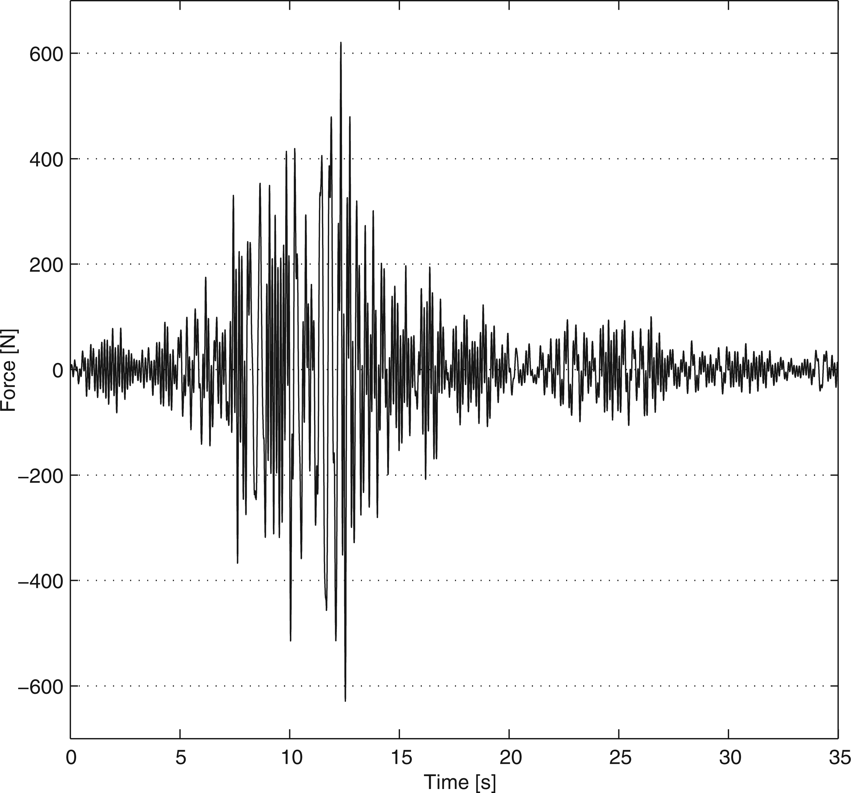
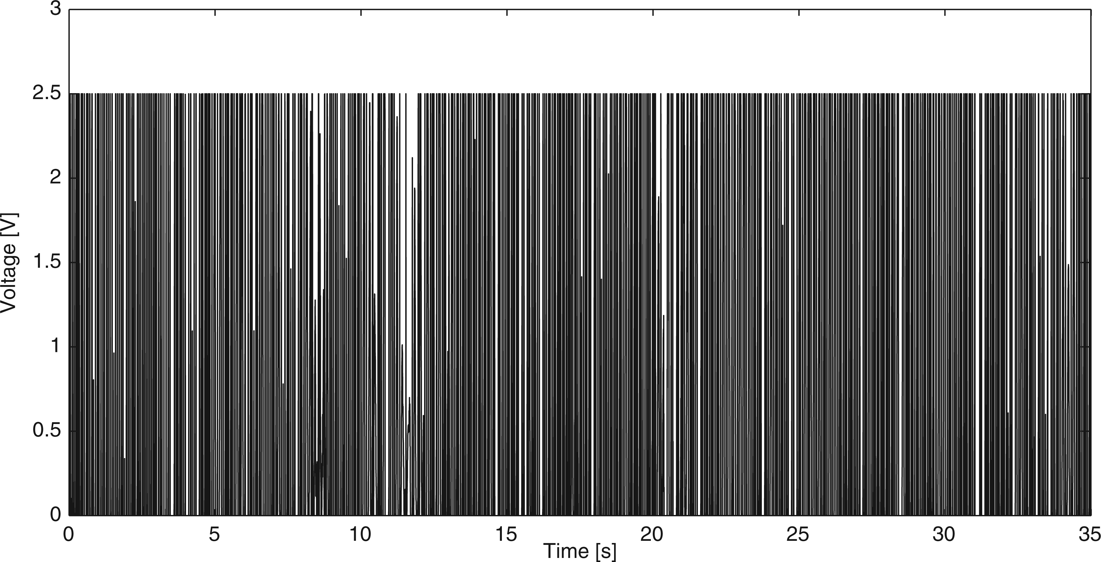
Simulation results, obtained after applying the control law in Equation (33) for the MRD voltage are presented in Figures 7–11.
First-story displacement with control (x1c) and without control (x1uc). Second-story displacement with control (x2c) and without control (x2uc). Third-story displacement with control (x3c) and without control (x3uc). Force at the MRD. Voltage at the MRD.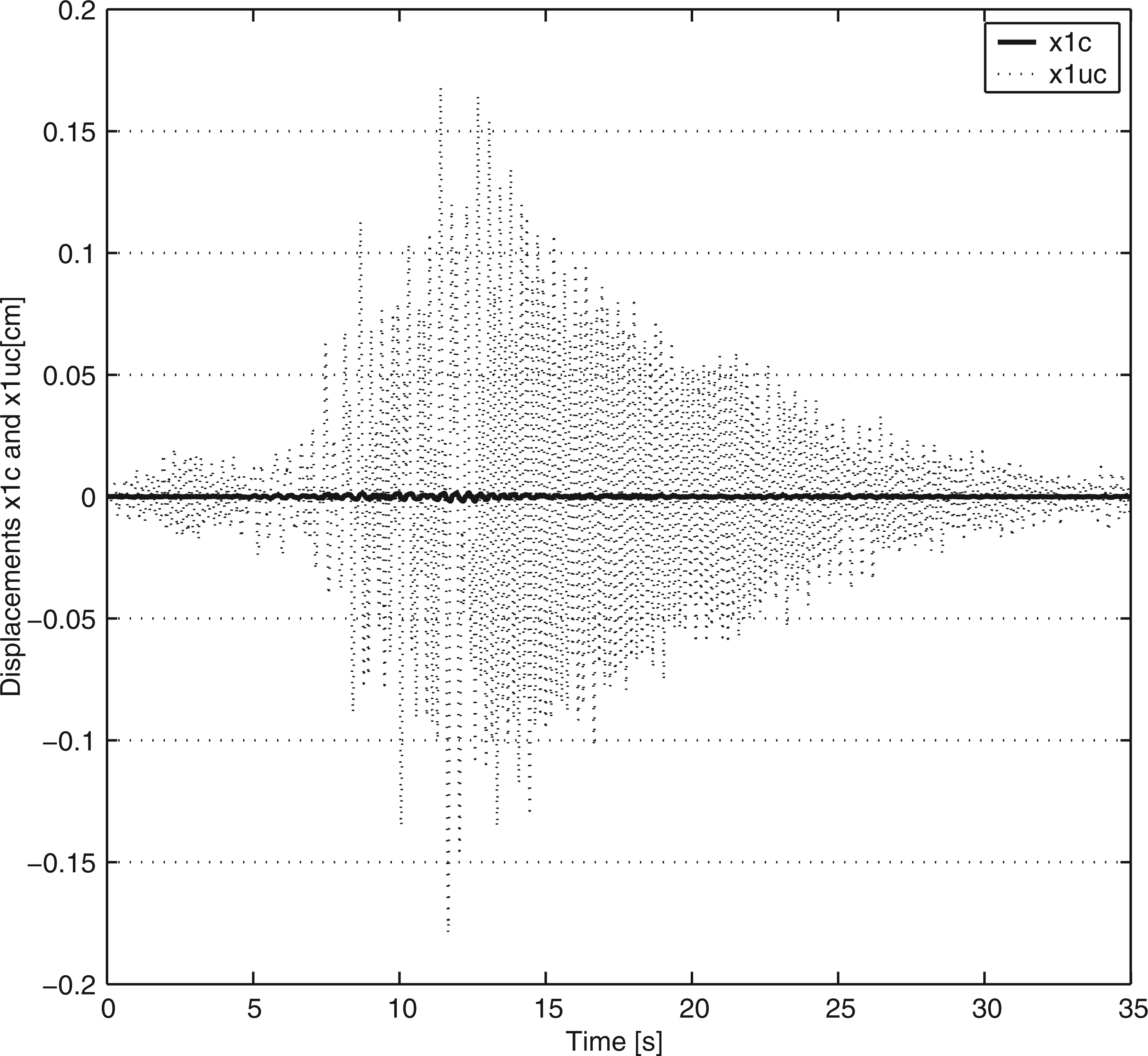
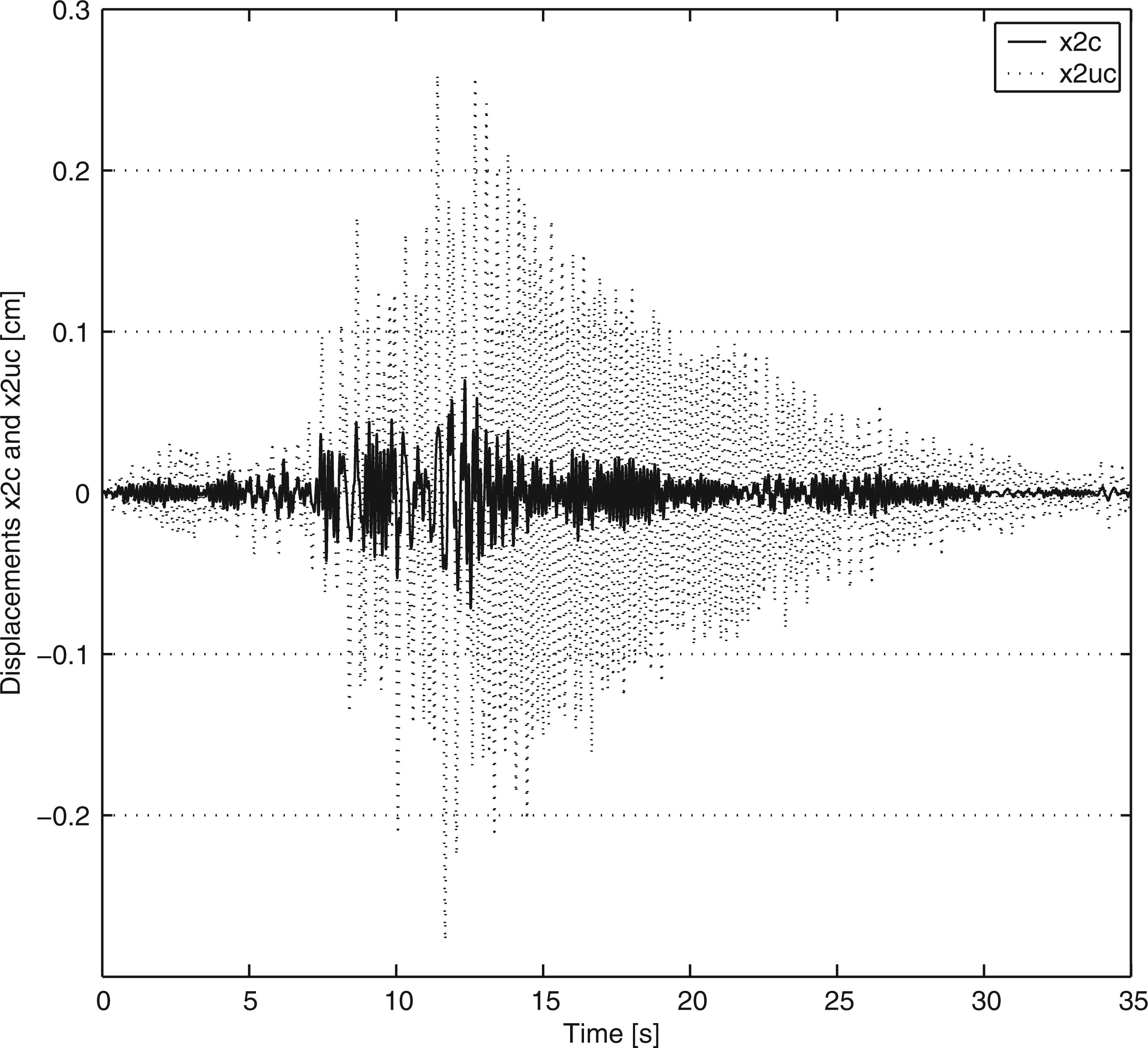
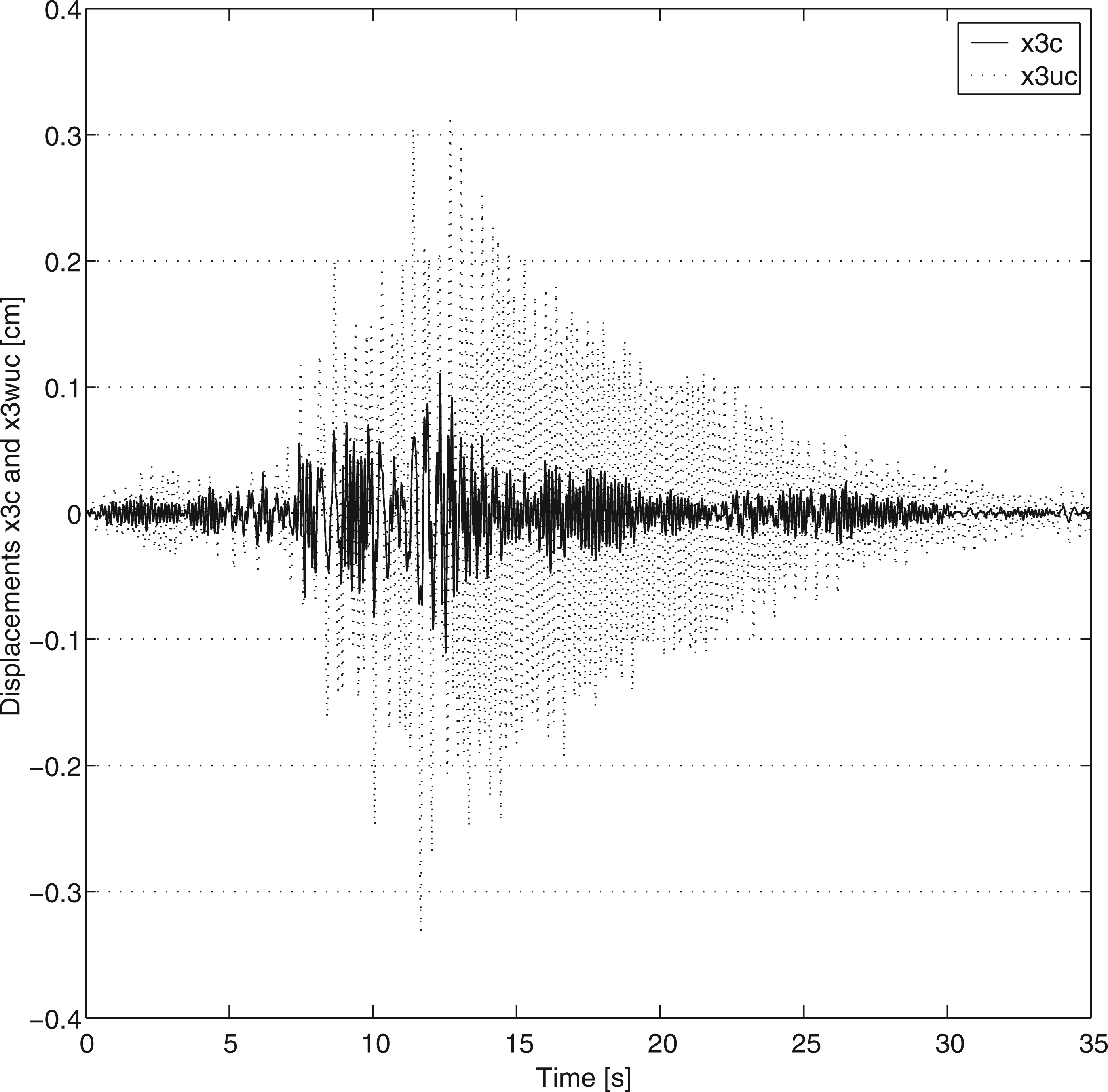
It can be easily appreciated that the inclusion of the IDA-PBC control law greatly reduces the size of the displacements of all stories. The impact is, naturally, larger in the first floor where the MRD is placed. Note, however, that in the third floor a reduction of about 70% in the size of the displacement is still observed. The magnitude of the displacement reduction avoids plastic deformation in the structure elements and helps to guarantee the safety of people and goods occupying the building. More details about the implication of semi-active control of civil structures can be found, for example, in Dyke et al. (1998).
The implementation of this control law requires an observer for z, because this variable cannot be measured. As shown in Martínez-Rosas and Alvarez-Icaza (2008) and Martínez-Rosas et al. (2009), this observer can be implemented together with the control law. The proposed design is simple as it takes advantage of the fact that z is bounded. It should be noted that a low value for z follows a low value of
The pattern of the control signal in Figure 11 looks similar to those encountered in sliding mode control. In this case the high-frequency switching is due to the nonlinear nature of the model of the MRD and the choice of gains for the control law. Lower gains in the control law yield less switching.
The strategy presented in this paper for vibration control is different from other strategies published in the literature (see Dyke et al. (1998), Jansen and Dike (2000), Yao et al. (2002), for example) in one important aspect. The designer has extra degrees of freedom in the choice of J d and R d that are not possible with the other approaches. With these degrees of freedom, the designer can decide to modify the natural frequencies for the feedback system, as is done in the other approaches, and has also the capability of modifying the vibration modes of the structure, or eigenvectors, associated with those natural frequencies. This vibration mode modification cannot be accomplished with the other techniques. In our example, this is accomplished by the choice of matrices K d and C d that includes terms that relate the first and third floor motions. This dynamic coupling can not be achieved with other methodologies.
7. Under-actuated double pendulum control
In this section the design procedure for the IDA-PBC control law introduced in Section 5 is used to control the under-actuated double pendulum with nonlinear friction in the joints that is illustrated in Figure 12, where q1 and q2 denote the angular positions of the two links, which are the generalized position coordinates; m
i
denotes the mass of link i with i = 1, 2, l
i
denotes the length of link i, l
ci
denotes the distance from the point of rotation of link i to its center of mass and I
i
denotes the moment of inertia of link i. Only the first link of this pendulum is actuated. For each one of the links a friction model of the form in Equation (2), with internal states z1 and z2, is used. The goal of the control law is to position the double pendulum in the upright position. This double pendulum is a two-link robotic arm. The application of dynamic friction models to this double pendulum was inspired by Martínez-Rosas and Alvarez-Icaza (2008), which shows the successful applications of a dynamic friction model to describe friction at the links of a three-degree-of-freedom robot.
Under-actuated double pendulum. Only the first link is actuated.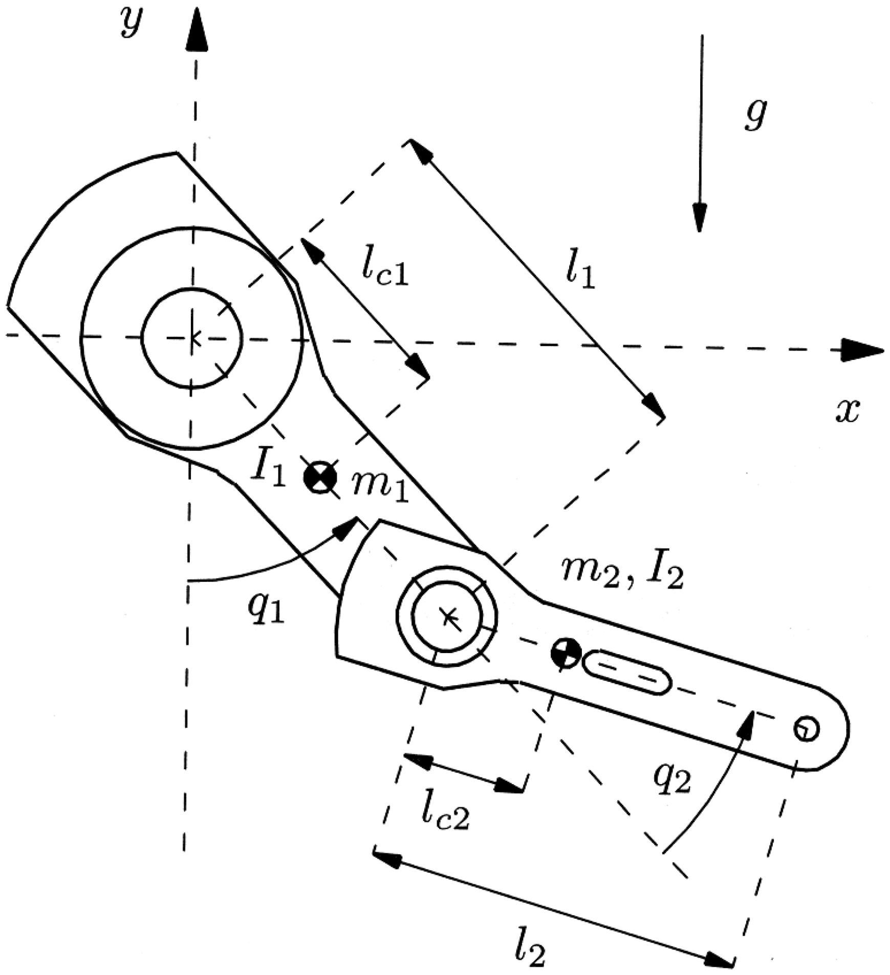
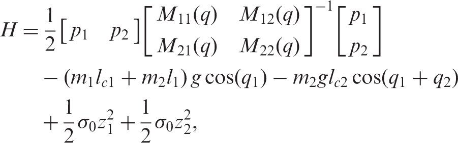
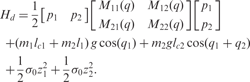
The energy function of the double pendulum with friction is
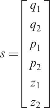
According to Equation (34) and following the procedure of the previous section, the PCHE for the under-actuated double pendulum with friction has the form in Equation (21) with
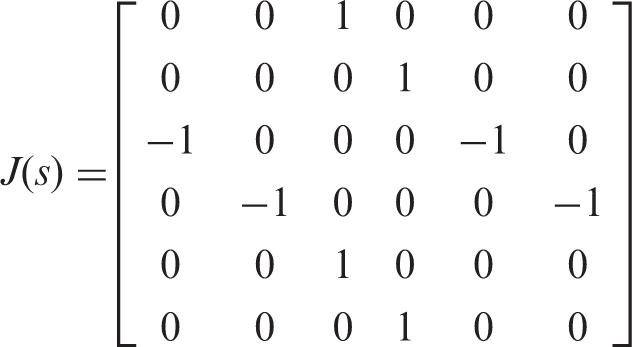
In Equation (35) J(s) = −J(s)T and R(s) = R(s)T ≥ 0 provided that the following inequalities hold

As the first step to design the control law, the following desired energy function is proposed
After following the procedure in Section 5, the PCHE for the desired energy function in Equation (41) has the form in Equation (11) with
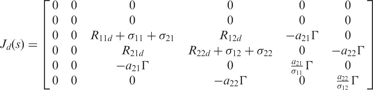
It can be noted that the interconnection matrix has not changes and that the damping matrix R d (s) is modified by the addition of desired damping terms R11d, R12d, R21d and R22d, that have the intention of speeding up the velocity of convergence of the control law. This is not the only possible choice of interconnection and damping. It was selected because of its simplicity.
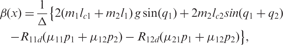
Solving Equation (17) for β(x), the control law, yields
To guarantee that matrix R d (s) is positive semidefinite, the new involved damping parameters can be selected using the Gershgorin circle theorem for diagonally dominant matrices (Demmel 1997).
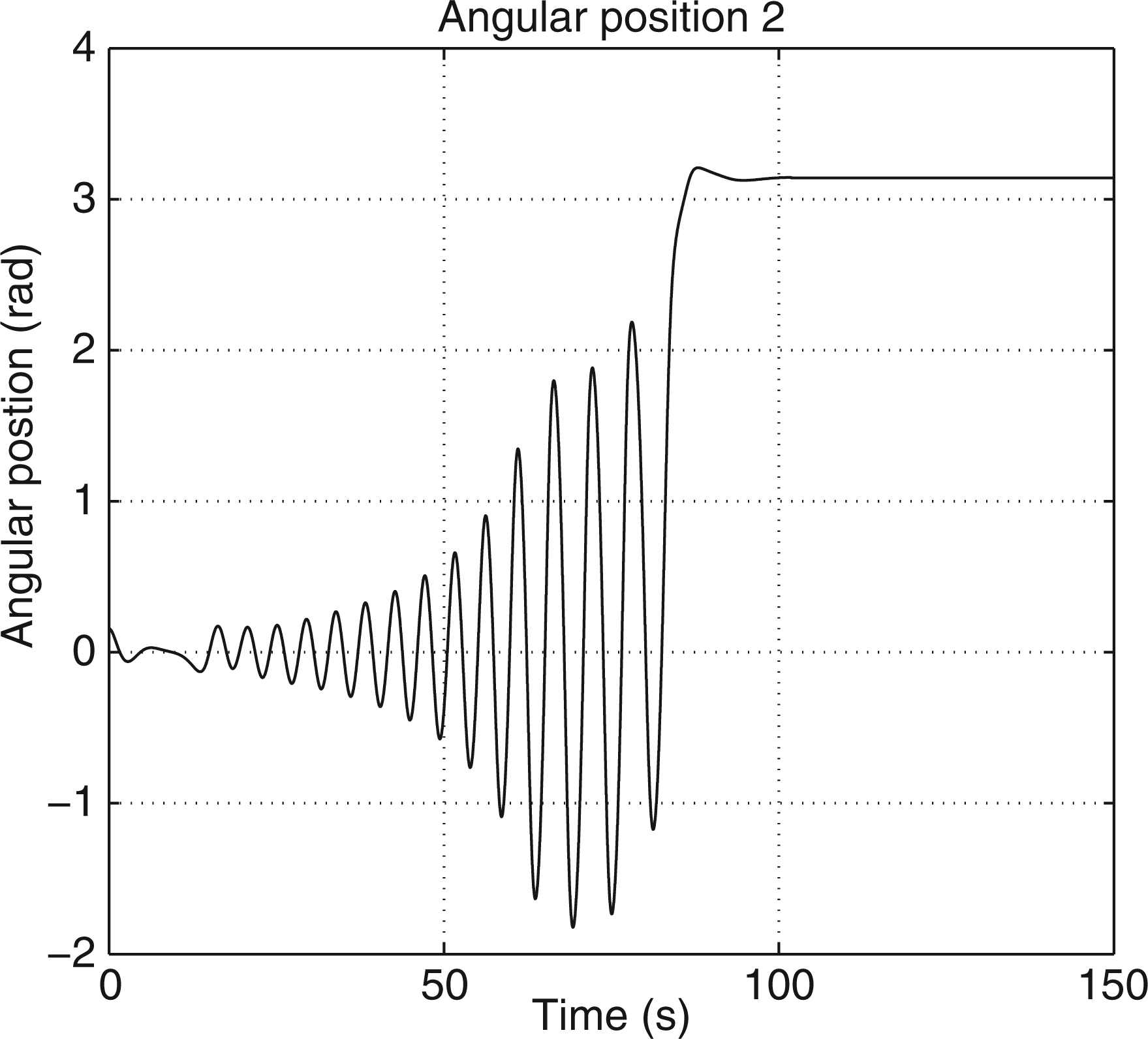
To show the performance of the control law in Equation (43) a simulation test was executed. The goal was to stabilize the under-actuated double pendulum in the open-loop-unstable upright position. For that purpose, the initial state was chosen as q1 = 36° and q2 = 18°, with no initial velocity. The parameters for the pendulum were obtained from Kelly and Santibáñez (2003) and the parameters for the friction model were obtained manually tuning them to match the available free response of the double and using the parameters in Martínez-Rosas and Alvarez-Icaza (2008) as start point.
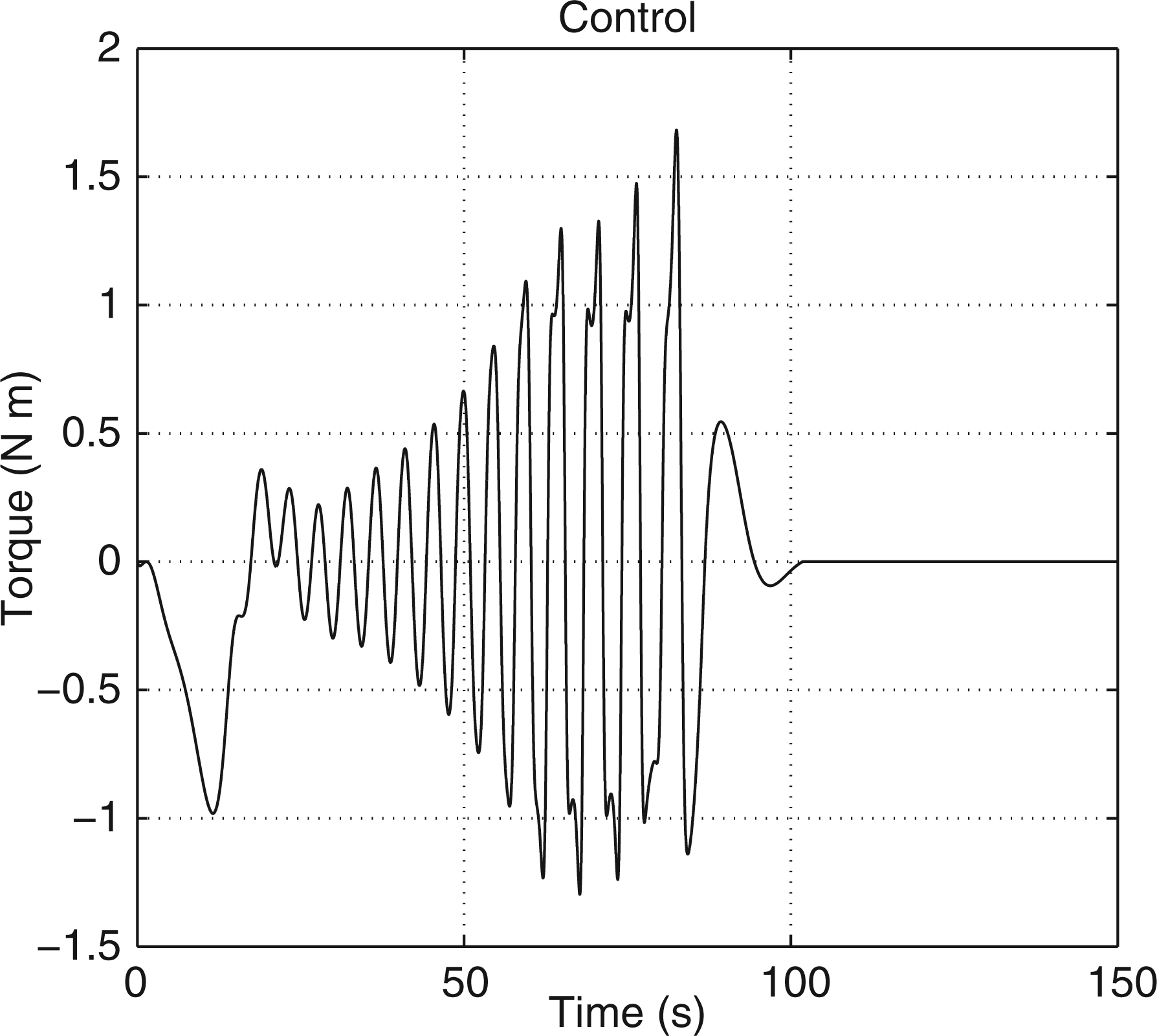
Figures 13 and 14 show the resultant angular position for links 1 and 2, respectively, after applying the control law in Equation (43). It is clear that the under-actuated double pendulum is stabilized by feedback to the open-loop-unstable upright position. Figure 15 shows the applied control signal, in this case the torque in the first link. It is interesting to note that this control law is unique and does not separate the process of initial swinging of the double pendulum and the final stabilization phase around the upright position, the common strategy for balancing this kind of pendulum.
Angular displacement of link 1. Angular displacement of link 2. Control signal: torque in the first link.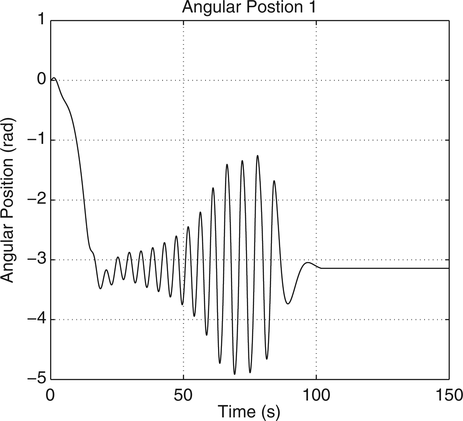
8. Conclusions
The IDA-PBC of under-actuated mechanical systems with nonlinear dynamic friction was presented. If the popular LuGre dynamic friction model is used to model nonlinear friction phenomena, it was shown that in order to preserve the Hamiltonian structure of the system when the state is extended to include the internal states of the dynamic friction model is considered, it is necessary to modify the LuGre model to take into account dynamic coupling between the model internal states and the states related to relative velocity of motion. The implications of this modifications were illustrated with two case studies: one civil structure with a MRD described by a nonlinear á la LuGre dynamic friction model and an under-actuated double pendulum with nonlinear friction in each of the two links. IDA-PBC laws were derived in both cases whose performance was tested by means of simulations.
Footnotes
Notes
Funding
This research was sponsored by CONACYT (grant numbers 47583 and 103640) and UNAM-PAPIIT (grant number IN108010).