
Abstract
Modal damping was conceived as a vibration control concept for potential application to a select set of long, flexible structures. This alternative approach was designed to exploit damping mechanisms inherent in the structures of interest by capitalizing on distinctive dynamic properties existing among vibration modes. The premise of modal damping is to transfer vibration energy from the fundamental mode where most vibration energy of civil structures of interest resides, to higher order modes where vibration impedance was shown to be more effective. A question was posed during its development concerning the subsequent risks to the structure. Spatial displacements, velocities and accelerations along the longitudinal axis will clearly be impacted and can readily be evaluated by simulation as required. The specific inquiry was directed at risks associated with redistribution of the damped vibration energy. In response, the distribution dynamics associated with the simple but ever-present anelastic damping mechanism was investigated and quantified. Furthermore, the analysis additionally offers support of the modal damping assertion by providing insight behind the increased dissipation effectiveness of the 2nd vibration mode over that of the fundamental mode.
1. Introduction
Tall, or long, flexible structures have long been known to be prone to low frequency, slowly decaying transverse vibrations that can be brought on by common external disturbances such as wind gusts. Vibrations will eventually decay due to natural processes such as friction or drag. Unfortunately, dissipation attributed to mechanisms inherent in such structures or through interactions with its environment is relatively slow. Equivalent damping ratios for these long and flexible structures are often less than 1% (Satake et al., 2002; Suda et al., 1996). In general, structural vibration damping is a property associated with one or more physical mechanisms (viscous, coulomb, hysteretic, interfacial (aerodynamic or soil), and structural/material which is also known as anelastic). These mechanisms principally act to convert kinetic energy in the context of a vibrating structure to heat that leads to dissipation and consequently to vibration decay. One or more of these mechanisms will affect the dynamic behavior of any given structure.
Modal damping (May, 2009; May and Menzemer, 2011), as employed herein, is a closed-loop vibration control concept directed at highly dynamic, yet structurally simple systems as characterized by aluminum cantilever poles, where overly sophisticated and expensive augmentations are not warranted. The vibration control approach is ‘modal’ in nature in that it attempts to redirect vibration energy from the fundamental mode where most vibration energy of civil structures of interest resides (Xu, 1996), to higher order modes where vibration impedance was shown to be more effective.
The simple aluminum roadside pole was selected as the baseline structure for this investigation. Due to its simple structural geometry, material damping became the mechanism of focus with regard to internal energy dissipation. Material damping is primarily attributed to friction occurring at the molecular level during the deformation cyclic (Dowling, 1999). The mechanism is referred to as ‘anelastic’ because it is associated with recoverable small strain deformation. The damped energy distributed along the structure’s longitudinal axis resulting from the anelastic mechanism served herein as the metric to evaluate potential effects and risks associated with modal damping.
2. Discussion
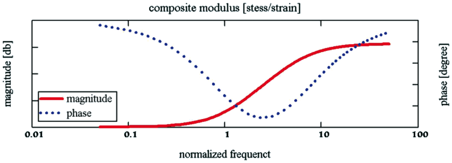
The modal damping approach attempts to capitalize on the inherent anelastic damping mechanism within the structure whose rheological model was found to take the form (Dowling, 1999) diagrammed in Figure 1. The anelastic mechanism’s frequency dependent behavior (typical) is diagrammed in the normalized magnitude/phase Bode Plot of Figure 2. The parallel/series springs (E1 & E2) and damper Anelastic damping mechanism rheological model. Anelastic damping mechanism frequency behavior (normalized).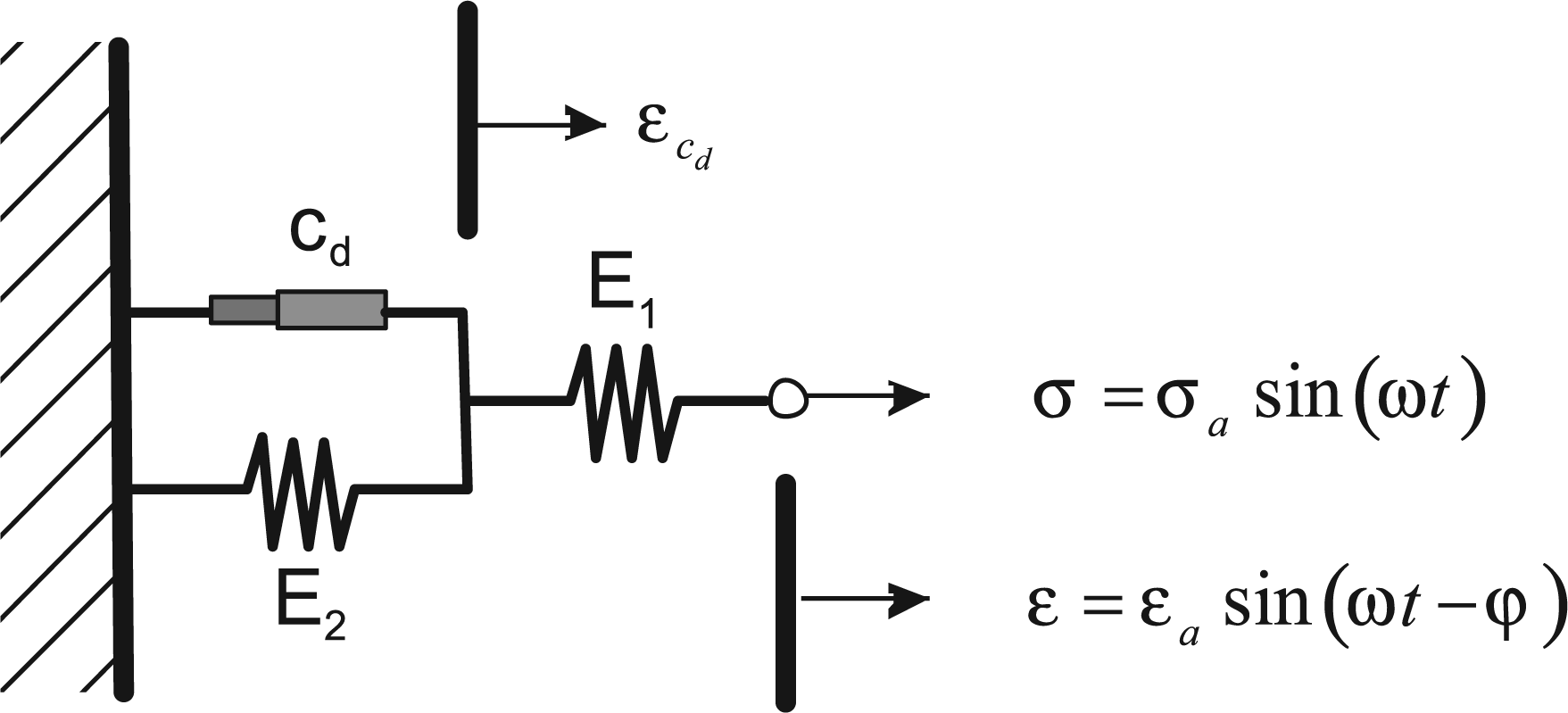
Deformation behaves elastically at frequencies below the lower breakpoint.
Deformation behaves elastically at frequencies above the higher breakpoint.
Deformation behaves viscously at intermediate frequencies between the breakpoints characterized by an expected phase difference between stress and strain. It is within this range where energy dissipation related to anelastic deformation occurs.
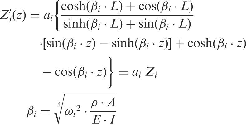
Dynamic responses of linear systems contain both natural and forced components. Anelastic deformations caused by either component can be shown to be functions of the structure’s characteristic mode shape functions. As such, the dynamics leading to energy dissipation in the following discussion are assumed to be driven by a state of free vibration. Closed-form expressions describing a structure’s natural mode shapes are extremely difficult to derive except for the simplest of structures – few real-world structures fall into this category. That being said, the typical roadside aluminum pole is nearly such a structure. Its analytical baseline is shown diagrammed in Figure 3, having a homogeneous and prismatic cross-section.
Mode shapes of a simplified cantilever structure.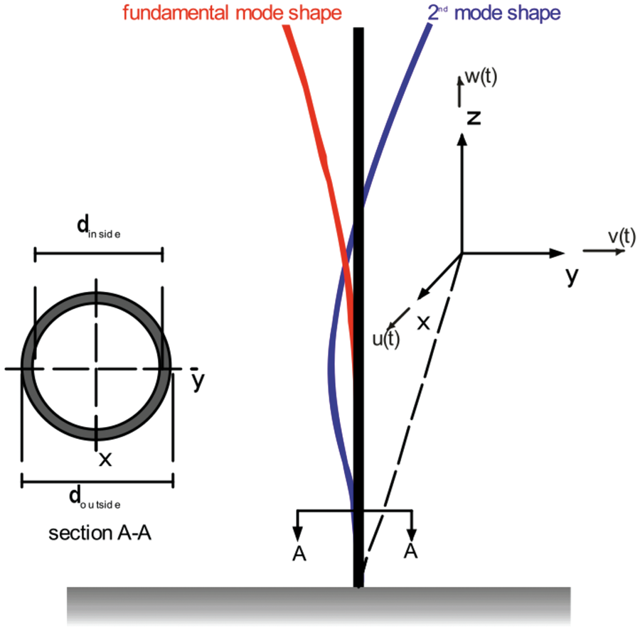
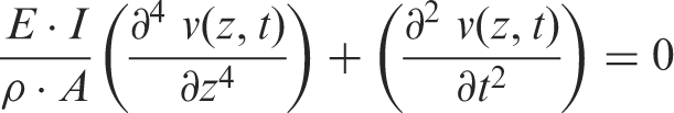
The defining equation of motion for the cantilever pole can be derived using Euler-Bernoulli-based principles of differential equilibrium:
The solution reveals that the dynamic response is the sum of a series of independent, albeit mathematically related, vibration modes that manifest themselves as distinct time-varying standing waves distributed along the length of the structure. The undamped solution is expressed as a function of both time and space,
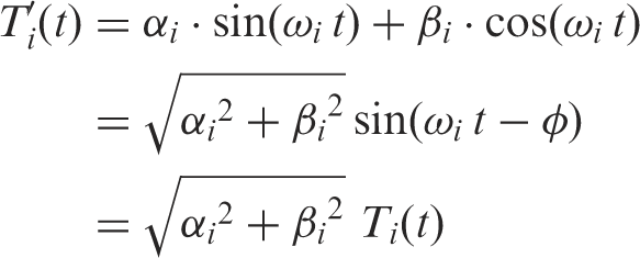
The scalar coefficients from both the temporal and spatial components could be combined to yield one scalar or amplitude coefficient,
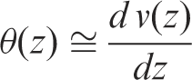
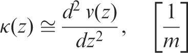
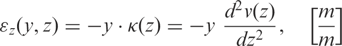
Lateral deflections relating to one or more mode shapes produce small curvatures along the longitudinal axis, such that
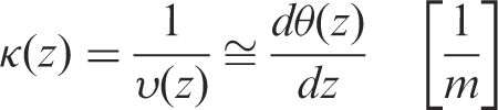
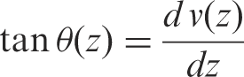
If θ is small, then
The curvature expression can be used to express the longitudinal strain distribution across the section at any point along the structure. Deformation across the section is assumed to remain elastic. For flexural bending in the y-z plane, where longitudinal strain is independent of x:
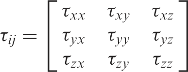
Interfacial stresses for any point within the pole can be generalized as
The conditions established for the vibrating pole yield the following general assumptions:
The pole is vibrating in the y-z plane. Inertial forces driven by the dynamic nature of the system produce flexural stress such that
The pole was given as being tall and flexible in character. Shear stresses become small relative to bending stresses so that

In summary, the assumptions yield a stress condition that reduces to one-dimensional form.
The anelastic model given in Figure 1 includes a viscous element. Inertial forces developed by the system produce harmonic deformation related to equation (8). A differential volume within the structure experiencing time varying flexural bending will be subjected to elastic and viscous stresses shown illustrated in Figure 4.
Stress components during elastic harmonic deformation.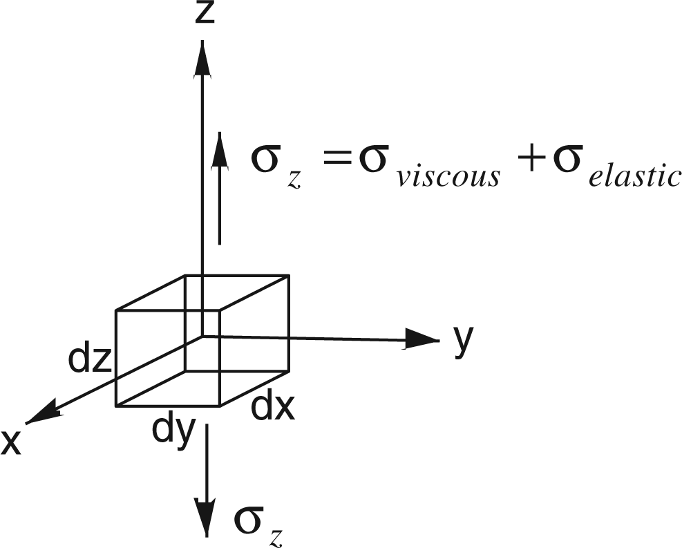
The viscous stress component can ideally be expressed as
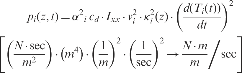
The units of the damping constant can be inferred from this stress-strain rate relationship as
The fundamental relationships noted to this point can now be applied to develop a mathematical expression that describes the distribution of dissipated energy within the structure. The development begins with the notion that the time-varying viscous deformation resulting from free vibrating structure spawns unrecoverable work as the viscous element converts work energy to heat. Consider the differential unrecoverable work converted within the noted infinitely small viscous-like element over some definite interval of time. At this point, let
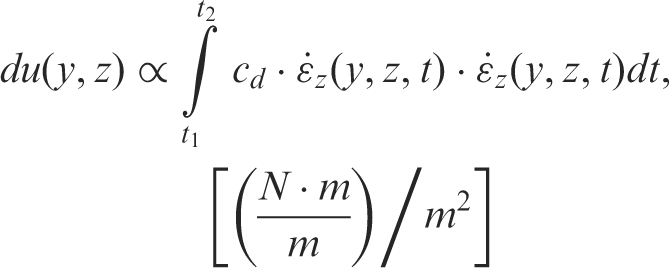
Dissipated energy (unrecoverable work) can alternatively be envisioned in terms of a transmission rate, i.e. dissipated energy per unit time, or damped power. The power expression has the advantage of providing insight into instantaneous behavior. Equation (14) can be reformed using the 2nd Fundamental Theorem of Calculus (Larson et al., 1998) yielding an expression for differential damped power within the deformed element:
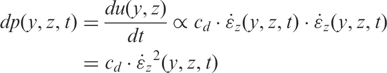
Substituting for strain from equation (8) and rearranging:
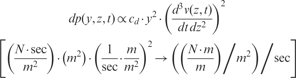
Integrating over the cross-sectional area yields an expression for damped power density within the cross-section at longitudinal position ‘z’ whose thickness is dz,
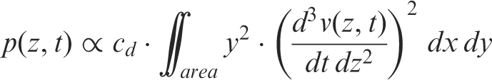
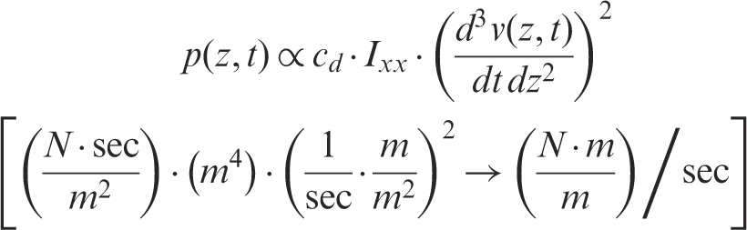
Both Ixx and cd are taken as constants (the baseline pole was assumed prismatic and homogeneous). Equation (18) is an expression of the damped power distribution along the longitudinal axis of the structure. It is a function of ‘time’ and ‘mode shape’. It is proportional to geometry and material properties.
The development began with the simplified notion that the viscous element does not experience the total strain produced by the flexural bending; ɛ cd ∝ ɛ z was given above. This notion can now be examined more closely by referring to the anelastic rheological model where
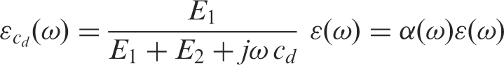
Equation (19) indicates that there will be both a frequency dependent scaled magnitude and a phase shift relationship between total flexural strain and strain of the viscous element. Phase shift of the damper strain does not factor into the magnitude of energy that is dissipated and will not be carried forward. Since the vibrating structure is characterized by distinct modes, the frequency dependent strain scalar can be represented as a modal dependent scalar
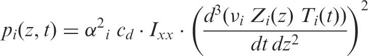
The time and spatial dependent components can be factored yielding
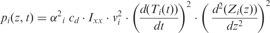
Since curvature is defined as
The time dependent component of equation (22) is given in equation (2). When substituted and operated on, the time component takes the following form:
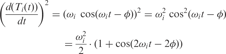
Equation (23) reveals that the modulating time component is periodically time varying at twice the sway frequency. It is continuously positive; it is shown diagrammed in Figure 5 relative to the sway of the structure. Its positive nature signifies that the damped power ‘flows’ in one direction, it is unrecoverable and is forever lost by the structure. As illustrated, one complete dissipation period occurs during each half cycle of sway.
Deformation damped power.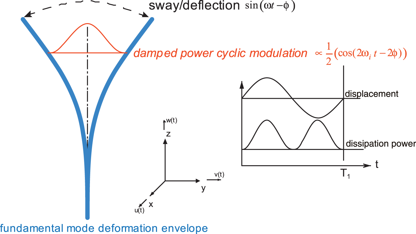
The damped power density at any point along the longitudinal axis follows from equations (22) and (23):

Maximum, or peak damped power for a given mode occurs when

Damped power distribution given by equation (24) is a function of space and time. The damped energy distribution, or the dissipated energy along the longitudinal axis, can be determined by the time integral of the damped power distribution. Consider the damped energy distribution during an interval equal to one complete sway cycle of the fundamental mode:
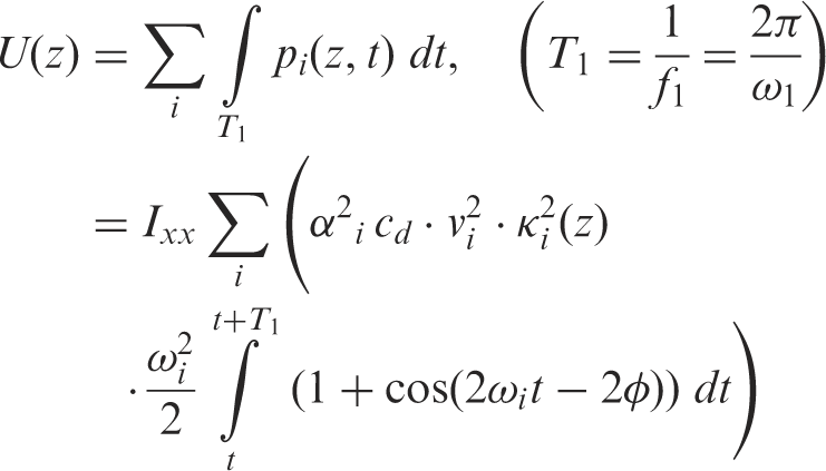
The damped energy distributed by the fundamental mode over one complete sway cycle is

Finally, the total damped energy can be found from the time and space integral of equation (24):
3. Modal damping risk evaluation
The damped power distribution function of equation (24) was analytically applied to a typical but simplified 12.8 meter roadside aluminum luminaire pole in order to investigate energy re-distribution effects of the modal energy transfer mechanism (May, 2009). The energy dissipation distribution immediately before the modal damping transfer was determined and compared with the distribution immediately after the transfer. The transfer scenario was emulated using MatLab/SimuLink (MathWorks™, 2007). Initial conditions established for the simulation generated a free vibration state with the majority of energy residing in the fundamental model. The modal damping event was executed several sway cycles into the simulation.
The idealized simulation revealed that a maximum of approximately 75% of the dynamic energy in the fundamental mode could be transferred to the 2nd vibration mode by way of the controlled modal damping transfer event. Analysis showed that the three-point tendon control device was the limiting factor (May, 2009). However, for this analysis, 99% energy transfer was investigated even though not truly attainable. The unrealistically high efficiency energy transfer was chosen to represent a worse case risk condition with respect to energy dissipation densities.
Figure 6 diagrams damped energy distributions along the longitudinal axis of the vibrating cantilever during an interval of time equal to the vibration period of the fundamental mode for the baseline pole, Energy dissipation distribution. (T = .867 sec, one fundamental sway period).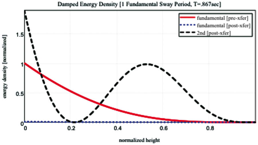
The three normalized damped energy distributions represent the immediately ‘before’ (fundamental) and immediately ‘after’ (fundamental and 2nd mode) anelastic damping behavior. The functional units represent damped energy per unit length, or a longitudinal damped energy density with units of the form
The damped energy distributions reveal two noteworthy points. First, the 2nd mode utilizes two primary regions of the structure to dissipate energy while the fundamental mode basically utilizes one. And second, the damped energy densities of the 2nd mode immediately within the base region of the structure are nearly twice those of the fundamental.
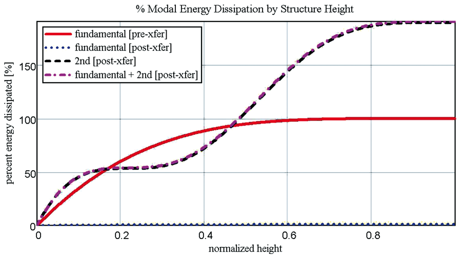
Figure 7 offers an alternate visualization of damping performance along the structure. It illustrates the spatial integral of the energy dissipation distribution functions shown above, taken along the longitudinal axis of the structure beginning at the structural base. All data is normalized to the 100% energy dissipation of the pre-transfer fundamental component. These plots reveal the following:
Almost the same amount of energy is dissipated in the lower 50% of the structure whether the vibration is fundamental (pre-xfer) or 2nd mode (post-xfer). The modal damping technique utilizes the third quadrant of the structure (50 → 75% of the structure height) to dissipate additional energy. For the assumed worst-case scenario in which 99% of fundamental energy was transferred to the 2nd vibration mode, an additional 82% overall energy dissipation occurs during the specified time interval equal to one vibration period of the fundamental mode – a sizeable efficiency improvement. % of total energy dissipation versus structural height (T = .867 sec, one fundamental sway period).
4. Impact of energy transfer efficiency
A 99% energy transfer efficiency was assumed for the modal damping event above, although not realistically attainable with the three-point tendon control device. The effect of lower energy transfer efficiencies on damped energy distribution was briefly investigated. Transfer efficiency conditions ranging from 0→99% energy transfer from the fundamental to the 2nd vibration mode were examined. The initial conditions for the transfer scenarios were similar to those used above where nearly all vibration energy initially resided in the fundamental mode.
The results are summarized in Figure 8(a), a contour plot of the superimposed post-transfer damped energy distributions of the fundamental and 2nd mode vibrating components. As would be expected, 2nd mode dissipation increases as transfer efficiency increases. The greatest dissipation per unit length occurs near the base for all conditions. As the transfer efficiency increases, dissipation increases in the third quarter (50–75%) of the structure’s height as expected.
Modal damping energy transfer effects. a) Energy dissipation distribution; b) % of total energy dissipation.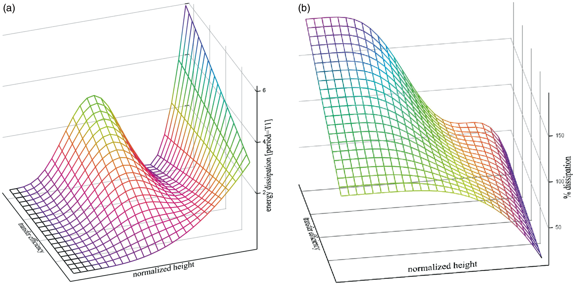
Figure 8(b) attempts to illustrate damping performance along the structure over the full transfer efficiency range. The findings are similar to those noted above for Figure 7.
5. Conclusions
Modal based damped power and damped energy distribution functions were developed for a tall, flexible cantilever structure characterized as a typical roadside aluminum luminaire pole. The structure was taken to be prismatic and homogeneous. The functions were developed to illustrate energy dissipation behavior of the anelastic damping mechanism. Since the vibration modes are orthogonal, distribution functions of the individual modes can be superimposed.
The anelastic dissipation models were used to evaluate energy redistribution risks associated with the ‘modal damping’ vibration control concept. Modal damping was developed to transfer dynamic energy between vibration modes to improve self-damping efficiency. The baseline transfer scenario utilized in this evaluation involved energy transfer from the fundamental to the 2nd mode.
Given a reasonably high fundamental to 2nd mode energy transfer efficiency for the modal damping implementation:
Damped energy densities immediately within the base region of the structure for the 2nd vibrating mode are noticeably greater than those of the fundamental mode.
Both the fundamental and the 2nd modes dissipate approximately the same energy over the lower 50% of the structures height.
The 2nd mode utilizes the third quadrant of the structure’s height (50 75%) to dissipate approximately 90% additional energy compared with the fundamental mode. The utilization of the third quadrant makes the 2nd mode significantly more efficient than the fundamental mode in terms of dissipating dynamic energy.
Footnotes
Funding
This research received no specific grant from any funding agency in the public, commercial, or not-for-profit sectors.