
Abstract
There is only one manipulation terminal for a flywheel in terms of the topology, which remains a potential bottleneck for its application in mechanical systems. This paper presents a two-terminal manipulation approach for the flywheel using the inverse screw transmission which yields the relative translation between two terminals resulting from the rotation of the flywheel. A dynamics model is accordingly put forward to describe both an ideal two-terminal mass and a non-ideal case including factors such as structure mass, friction, backlash and elastic effect. A prototype device is manufactured and subsequently characterized using a vibration rig to identify the model parameters. The results show that, in the commonly used frequency band, the effect of non-ideal factors is insignificant and thus the device can be regarded as an ideal two-terminal mass. However, the impact of the non-ideal factors should be taken into account in the other frequency ranges. The proposed two-terminal approach releases the ground terminal of the flywheel and has a great application potential in vibration control.
1. Introduction
The flywheel is one of the most popular mass components for vibration suppression.
The literature (Aoustin et al., 2006; Ghedamsi et al., 2008; Tso and Li, 2008) has described different flywheels for vibration and other related applications. However, the input and output nodes (also known as mechanical terminals or simply terminals) of the force and displacement for a flywheel are in fact the flywheel itself, which means that the flywheel has only one genuine mechanical terminal in its inertial space. Interms of the topology, a component in a mechanical system should have at least two terminals. To facilitate the analysis of a flywheel, the ground of its inertial space is often regarded as a virtual terminal, which can be found from the mechanical symbol of the flywheel shown in Figure 1(a). As shown in Figure 1(b) and 1(c), for genuine two-terminal components such as springs and dampers, the relative force causes relative displacement of two terminals. However, as pointed out by Willems (2010), the flywheel as one of the typical mass components has only one genuine terminal for force and displacement handling, and a virtual terminal that is restricted by the ground of the inertial space. For this reason, the application potential of a flywheel cannot be fully materialized.
Mechanical symbols for passive vibration components. (a) is the expression of a flywheel, where the genuine mechanical terminal of the flywheel is itself, and the ground is regarded as its virtual terminal. (b) and (c) respectively shows a spring and a damper. Each of them has two genuine terminals.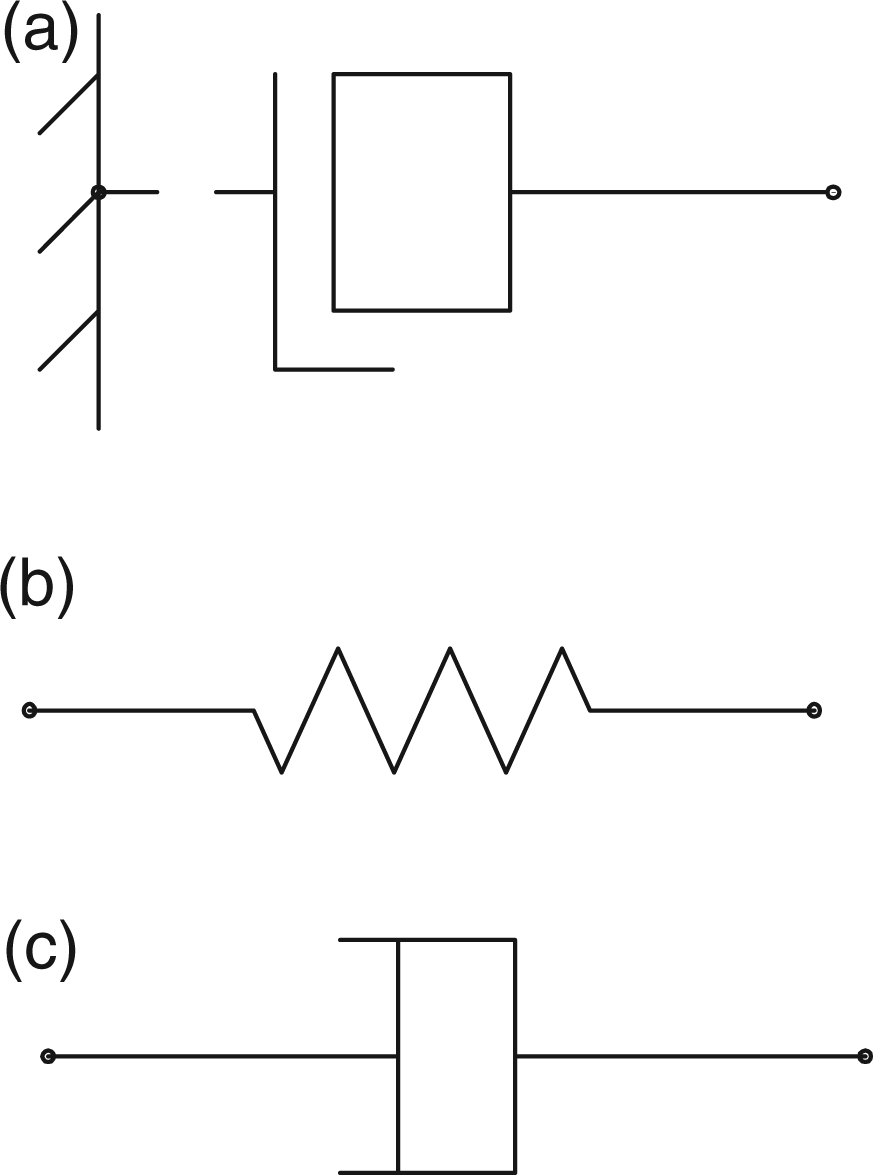
In view of the above, a two-terminal manipulation approach is proposed for the flywheel (named as two-terminal flywheel) and the vibration suppression applications are investigated. This manipulation mechanism can be accomplished using an inverse screw transmission. Screw transmission has been widely used for many devices with rotation as input and translation as output (Maeda and Sato, 2008; Mundo and Yan, 2007). Liang et al. (2003) proposed a special screw transmission mechanism whose rotation resulted from the rectilinear displacement. Zhou et al. (2003) applied it to a robot joint and named it as an inverse screw transmission mechanism.
To reduce the gravitational mass in passive vibration control systems, Rivin (2003) introduced the concept of a motion transformer, which could reduce the gravitational mass while improving the inertial mass in a vibration isolation system based on the concept of an inverse screw mechanism and the flywheel installed on anut. Zhu et al. (2006) calculated a single degree-of-freedom vibration isolation system with the motion transformer and realized “virtual mass” that is 400 times the gravitational mass. Smith (2002) developed a mechanical transmission flywheel, also known as the“inerter” that has two manipulation terminals. Evangelou et al. (2006) presented a motorcycle steeringcompensator using the concept of the inerter. Compared to conventional steering dampers, the inerter employed by Papageorgiou (2009) significantly improved the dynamic properties of the primary oscillatory modes, known as “wobble” and “weave”. Wang et al. (2007) investigated the performance benefits of building suspension control employing inerters. Their result shows that inerters, if properly applied, are indeed effective in improving system performance. Liet al. (2010a) proposed the electromechanical analogy design theory of the spiral flywheel motion transformation system and applied it to the suspension vibration control (Li et al., 2010b).
The motion transformer and the inerter are similar in that they both have two manipulation terminals for a flywheel. However, aforementioned researches installed the flywheel on the nut. With the translation between the screw and the rack, the nut drove the flywheel to rotate. Also these researches mainly focused on the motion transformation, without considering the non-ideal factors of an actual device. In this paper, we employ the simplified inverse screw transmission mechanism whose screw is installed with the flywheel. The relative rectilinear displacement between the nut and the rack causes the rotation of the flywheel to realize the two-terminal mechanism.
Taking the non-ideal characteristics into account, a prototype device of the two-terminal flywheel is characterized on a vibration rig to validate its ideal two-terminal mass and other non-ideal factors.
As the first part of the work, the rest of this paper is structured as follows. Section 2 presents an approach for mechanism synthesis and an equation to calculate the ideal inertial mass of the two-terminal flywheel. Section 3 analyzes the influence of the non-ideal factors, i.e., the structure mass, friction, backlash and elastic effect. An actual dynamics model incorporating both ideal and non-ideal factors is developed accordingly in this section. In Section 4, a prototype device and a test setup are described. The model parameters are then identified in accordance with the experimental results. Conclusions are drawn in Section 5.
2. Two-terminal manipulation mechanism synthesis
2.1. Two-terminal manipulation approach
The variations of the forces applied to the two terminals of a vibration component lead to relative displacement and also cause vibrations, and vice versa. Considering the rotary condition, let M1 and M2 denote torques, and θ1 and θ2, angular displacements of two rotary terminals. The relative torque M = M1-M2 leads to the relative angular displacement θ = θ1-θ2. For the elastic component such as torsion spring withtorsional stiffness coefficient k, M = kθ. When the torsional damping coefficient is c, one has
As described in Section 1, on the contrary, the flywheel has only one genuine terminal whereas the ground of its inertial space is a virtual terminal. As such there are M2 = 0 and θ2 = 0 for the virtual terminal of the flywheel. Hence, the relative torque between two terminals reduces to M = M1, and accordingly the relative angular displacement, θ = θ1. For the flywheel with moment of inertia J, there is

To realize two relative translational terminals, proper transmission mechanism is considered for the two-terminal manipulation of the flywheel. According to the requirements of rectilinear inputs at two terminals and rotary output from the flywheel terminal, the input motion eigenvector Ei and output motion eigenvector Eo of the mechanism can be written as follows (Wang et al., 2003)
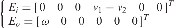
where the first three elements in the eigenvectors represent rotations around x, y, and z axes and the second three stand for translations in x, y, z directions respectively. For the associated transformation matrix

there is a non-zero vector element, i.e.
All the rest elements of the matrix A are 0. Therefore, the two-terminal manipulation issue of the flywheel is converted as the synthesis of
As shown in Figure 2, when fixing terminal 1 (left) of the mechanism, the translation at terminal 2 (right) causes the screw and the flywheel to rotate. In this way, the force and the displacement at the flywheel terminal are transmitted to terminal 2. Similarly, if terminal 2 is fixed, those of the flywheel terminal are transmitted to terminal 1.
Kinetic sketch of the inverse screw transmission-based two-terminal manipulation mechanism for the flywheel.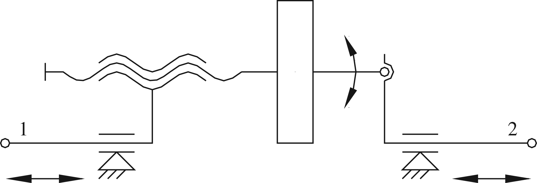
2.2. Ideal inertial mass
The main purpose for the above transmission is to convert the translation into rotation and hence add the second terminal. Figure 3 shows the simplified schematic diagram of the inverse screw transmission mechanism. Let D denote the pitch diameter and α the helix angle. When operating as depicted in Figure 2, the rectilinear displacement x of the nut resulting from relative force F = F1-F2 leads to the rotary displacement θ of the screw (Figure 3).
Schematic diagram of the inverse screw mechanism.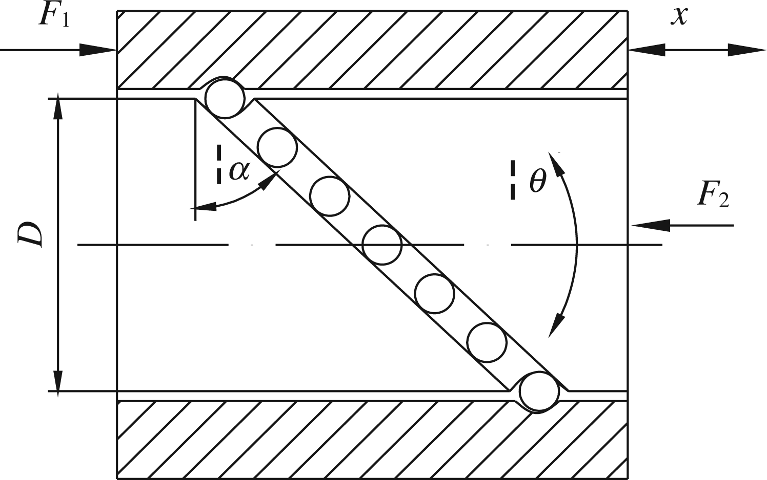
With reference to the displacement triangle shown in Figure 3, the translation x yields the angular displacement θ output from the screw
To simplify discussion, all the non-ideal factors are temporarily omitted in this section. Such factors will be included in Section 3. The circumferential force

where α is the helix angle. Accordingly the torque of the screw is
Owing to the torque equality between the screw and the flywheel, combining equations (1) and (7) gives
From the above equation, the angular acceleration
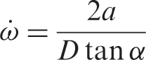
where a is the acceleration of the nut.
Substituting equation (9) into equation (8), one has
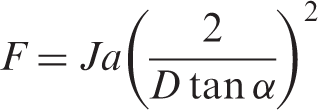
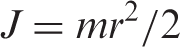
For the regular cylindrical flywheel with radius r, the moment of inertia J is given by
Considering equations (11) and (10), one obtains
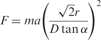
Let
3. Non-ideal factors of the two-terminal manipulation structure
As shown above, with two-terminal manipulation of the flywheel, the inverse screw mechanism can help to achieve an ideal inertial mass that is b times of its gravitational one. However, an actual device is also restricted by the friction and other factors, which lead to reduced transmission efficiency. The effects of these factors are examined as follows.
The first non-ideal factor introduced here is the structure mass mr of the device. As discussed above, due to its grounded virtual terminal, structure mass mr cannot be simply merged with the ideal two-terminal inertial mass mt. Instead, it is regarded as an additional single-terminal mass component for the device.
In addition, friction always occurs on the contact surfaces. Figure 2 shows that there are two kinematic pairs, namely, the inverse screw kinematic pair and the bearing pair. According to the friction model including Coulomb and viscous frictions (Southward et al., 1991), the rotary friction f(t) of the device is presented as
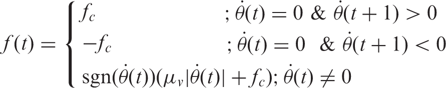
where fc is the Coulomb friction,
Combining equations (5) and (13) in Laplace domain leads to
subject to an initial condition
In this way, the friction is transformed to a special damper whose damping coefficient is
Since
Moreover, backlash and elastic effect are also non-ideal factors. In order to reduce the transmission friction and machining errors, a proper backlash is necessary for a kinematic pair. The smaller the backlash, the higher the transmission precision is, which however causes higher friction.
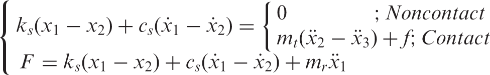
Figure 4 shows the backlash and the deformation (elastic effect) schematic diagram. F = F1-F2 is transmitted via the nut-screw-bearing path, through which the backlashes ε1, ε2, the stiffness ks and the viscous damping cs influence the ideal mass of the transmission.
Schematic diagram of the backlash and deformation of the structure.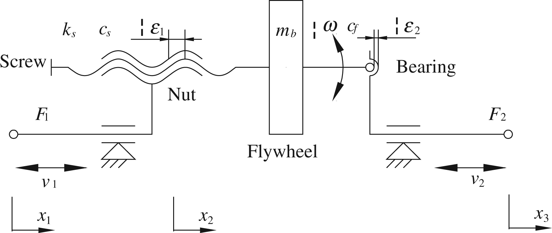
Suppose that the deformation of the screw is x1(t)-x2(t). The corresponding F(t) is given by

Taking the effect of the backlashes ε1 and ε2 into account, there are two conditions for the mechanism, that is, contact and noncontact, which can be judged by the following equations

Having considered both non-ideal and ideal dynamic characteristics, the complete dynamics model can then be illustrated in Figure 5. In the figure, mb denotes the ideal inertial mass; mr, the structure mass; cf, total friction; ks, the structure stiffness, cs, the structure viscous damping; and ε1+ε2, total backlash.
Dynamics model of the inverse screw transmission-based two-terminal flywheel.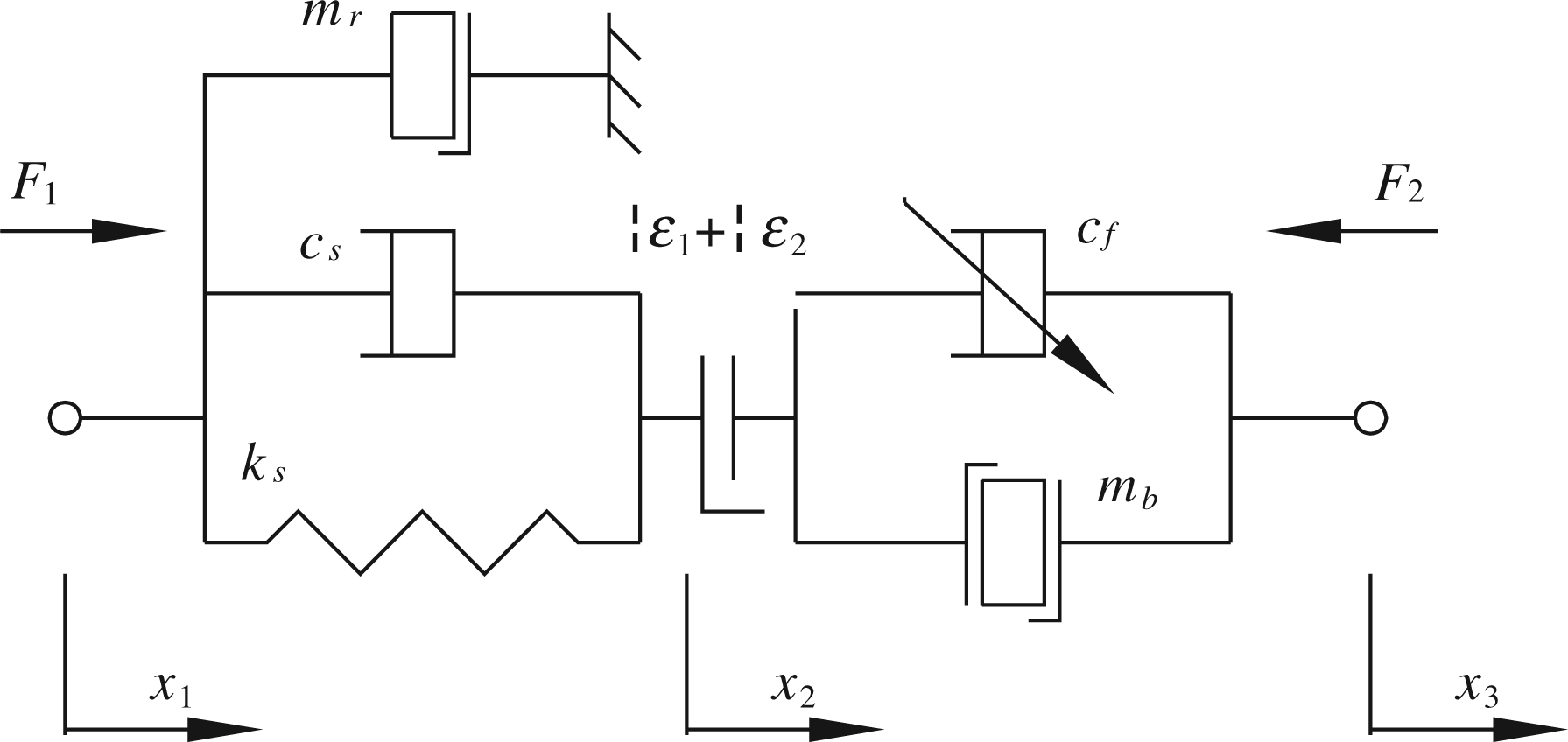
Combining equations (13) to (16) in accordance with Figure 5 leads to following dynamics equation of the two-terminal flywheel
4. Experimental identification
4.1. Test setup
Figure 6(a) shows an inverse screw transmission-based two-terminal flywheel prototype device manufactured by the Engineering Laboratory of Detection, Control and Integrated System, Chongqing Technology and Business University. The sectional view of the device is shown in Figure 5(b). The total mass of the device is 2.253 kg, with a flywheel of 0.738 kg. The structure mass is accordingly mr ≈ 2.253-0.738 = 1.515 kg. Calculated using equation (12), the ideal inertial mass of the device is 297.0673 kg (including the shaft embraced by the flywheel). In addition to the flywheel, all the other rotary parts, such as the screw and the internal ring of the bearing, have the magnified two-terminal inertial mass which is approximately 2.4233 kg. Hence the total free two-terminal inertial mass of the device is mt = 299.4906 kg (= 297.0673 + 2.4233).
Prototype device of the two-terminal flywheel. (a)shows the picture and (b), structure schematic diagram.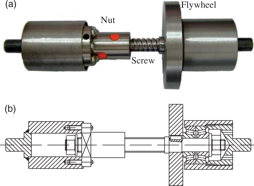
A PLD-20 test rig, as shown in Figure 7, is employed to verify the dynamic characteristics of the two-terminal flywheel. The prototype device is clamped between a hydraulic actuator and a load cell which is fixed to the crossbeam directly above it.
Two-terminal flywheel prototype device on the rig.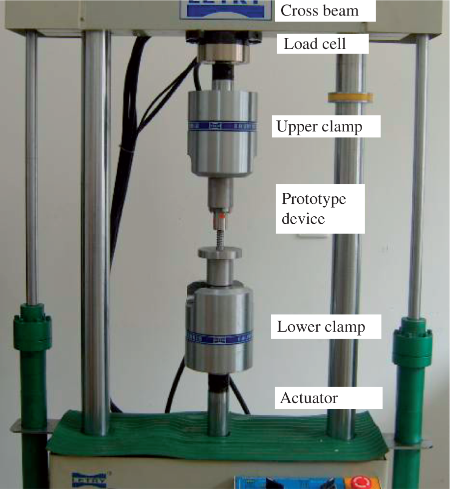
According to the amplitude and frequency of the signal waveform input from a computer, hydraulic power source drives the actuator via a servo valve controlled by a PID algorithm.
One terminal at the top of the rig is connected to the load cell that measures the inertial force F(t). Another terminal is rammed by the actuator driven by high pressure oil from a hydraulic power unit, imposing a predefined displacement x(t). The displacement is measured using a built-in linear variable differential transformer (LVDT) displacement sensor. With a displacement input x1(t)-x3(t) from the actuator, the rig yields the force F(t) at the load cell. Both displacement and force signals are acquired by a data acquisition system and then transmitted to the computer for further processing.
4.2. Experimental design
Although the two-terminal flywheel is ideally a mass component, it is, in fact, a dynamics system depicted by Figure 5. There have been different sophisticated methods developed to identify the dynamics parameters in time or frequency domain for a mechanical system (Feldman et al., 2009; Metallidis et al., 2008). Here we propose a parameter fitting approach to identify the model parameters of the device.
As different dynamics parameters of a system may be sensitive to different frequencies the experiments may be conducted in different frequency bands to identify different parameters. In each experiment, only dominant parameters are tuned in a time domain tofit the test results. To guide the tuning process, it is proposed to use the minimum deviation from the actual system output as tuning criterion, i.e.,

where Yexp is the measured system output; Xexp measured system input, Pi the ith model parameter to be tuned, and Yth theoretically fitted system output using tuned parameters. In this way, the proposed experimental design takes both frequency and time domain into account, which helps achieve acceptable precision with a rather simple process.
Let the inertial force F(t) = Y and the predefined displacement x(t) = X. As shown in Figure 5, there are six components each associated with one parameter, except the friction component for which two parameters, fc and
Before the tests, F(t) and x(t) should be set to zero to eliminate the influence of the structure mass. According to the proposed parameter fitting approach, our experiments are composed of three stages. The first one is performed at a lower frequency to identify the low frequency sensitive parameter, fc. Then we move to a relatively higher frequency to identify the remaining parameters. At last stage, we shift to a frequency in the commonly used band to validate the tuned parameters.
4.3. Identification results
The first experiment is conducted at 0.053 Hz with an amplitude of 15.1 mm, where the deformation, the backlash and the viscous friction are very small and can be neglected. Thus equation (17) can be re-cast as

Figure 8 shows the comparison between the measured force Fexp(t) and the calculated inertial force,
Figure 8 also shows that the noise component of the first experiment is relatively large, mostly resulting from the noise of the acquisition system, the leap due to the impurities in lubricant of the kinetic pair, as well as theconcentricity error between two hydraulic clamps of the test rig.
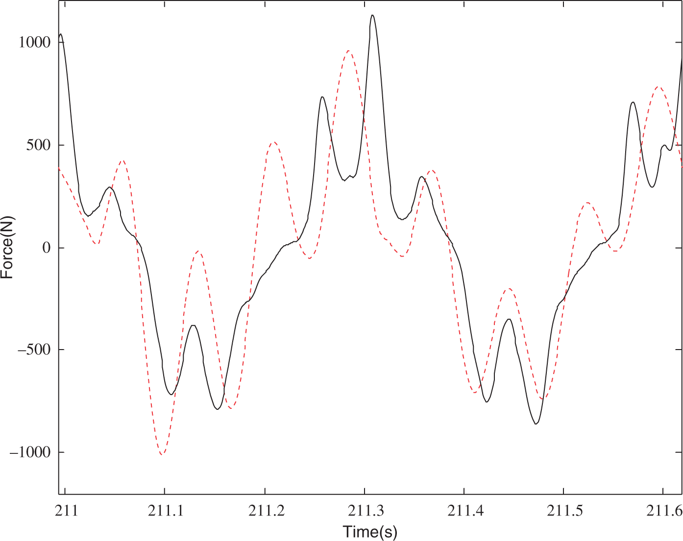
The second test is then carried out to identify the remaining four parameters. Since the four parameters are insensitive to low frequencies, we increase the frequency of the displacement input x1(t)-x3(t) at theactuator (Note: one of x1(t) and x3(t) is zero, the other is a sinusoidal function). The measured frequency and amplitude are respectively 3.2 Hz and 4.16 mm. With these inputs, equations (17) and (18) yield the following optimal values for the four parameters ε1+ε2 = 0m, ks = 2100kN/m, cs = 1200N.s/m and fc identification experiment (frequency 0.053Hz and amplitude 15.1mm), where the solid line is Fexp(t) and the dashed line, Comparison between Fth and Fexp, where, Fexp is represented by the solid line, and Fth, the dashed line (frequency 3.2 Hz and amplitude 4.16 mm).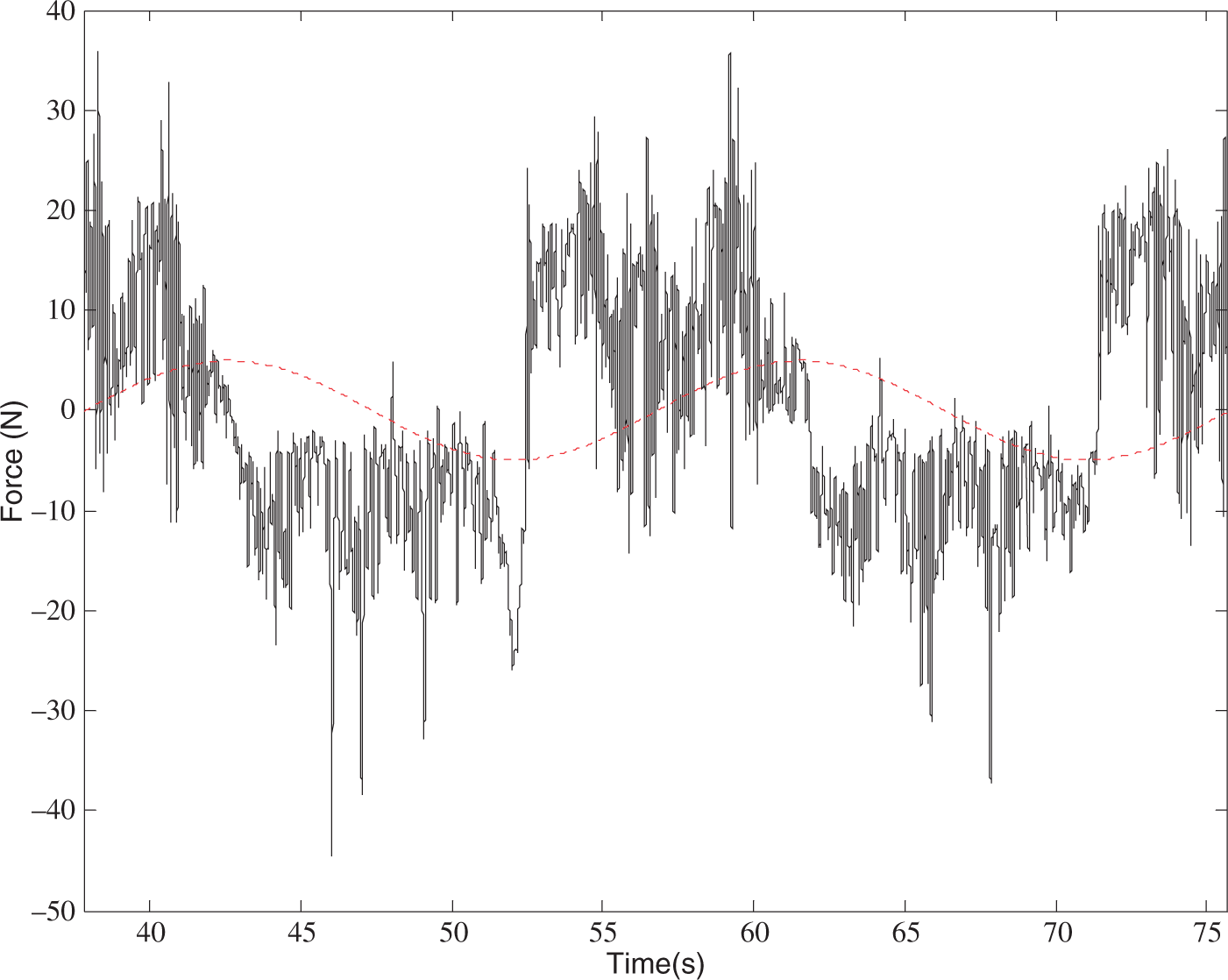
To further validate the appropriateness of the identified model parameters, another sine wave displacement x1(t)-x3(t) with frequency 15.9 Hz and amplitude 0.806 mm was inputted. The resulting Fexp(t) and Fth(t) are in very good agreement as shown in Figure 10. Thisonce again demonstrated the effectiveness of the proposed dynamics model.
Comparison between Fth and Fexp, where Fexp is expressed by the solid line, and Fth, the dashed line (frequency 15.9 Hz and amplitude 0.806 mm).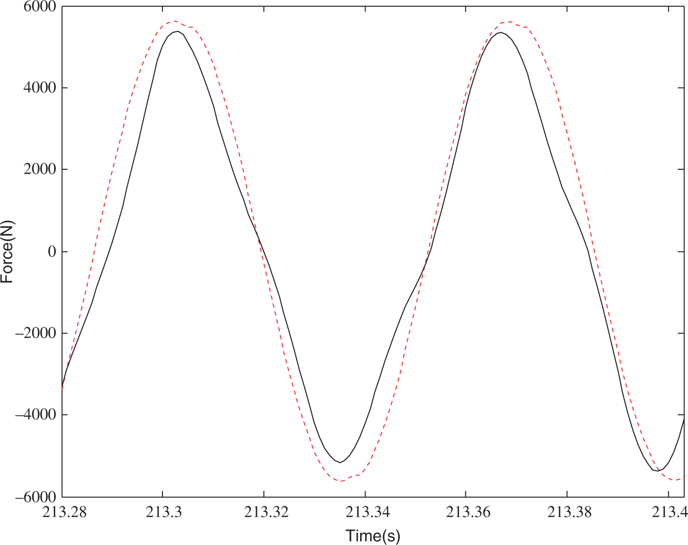
It is worth noting that, moreover, with the increase of the frequency, the variation pattern of F is more close to the predefined sine wave. The reason is that, the higher the frequency, the bigger the inertial force will be and the lower the friction impact as well.
Combining equations (13) to (18) and identification results of the prototype device leads to the governing equation of the two-terminal flywheel, which is expressed in Laplace domain as
where as obtained above mt = 299.4906, cs = 1200, ks = 2.1×10⁶, and cf = 31.4, The initial condition of F is a nonzero value given by
On the one hand, ks>>mt results in
Comparing equation (20) with equation (21), it is clear that, regardless of the complete dynamics model shown in Figure 5, the two-terminal flywheel can be treated, ideally, as a free two-terminal mass component with inertial mass mt. This magnifies the gravitational mass m of the flywheel by b folds as explained before.
Based on equations (20) and (21), magnitude-frequency and phase-frequency responses can be displayed in Figures 11(a) and (b) respectively. Figure 11(a) shows that, the non-ideal influence of the inverse screw mechanism on its dynamics is insignificant in the middle band (0.1-40 rad/s in this case) that covers much of the real applications. The impact on the ideal dynamic characteristics for the transmission structure is relatively large in the lower or higher frequency bands. Similarly as shown in Figure 11(b), an actual device has less effect on the phase angle under intermediate frequency range. When the frequency increases to certain extent, there is obvious phase difference between the ideal and complete dynamics models for a two-terminal flywheel.
Comparison of amplitude-frequency and phase-frequency responses of the two-terminal flywheel. (a) is the amplitude-frequency response and (b), the phase-frequency response. The real line represents the ideal response, whereas the dashed line, actual dynamics model.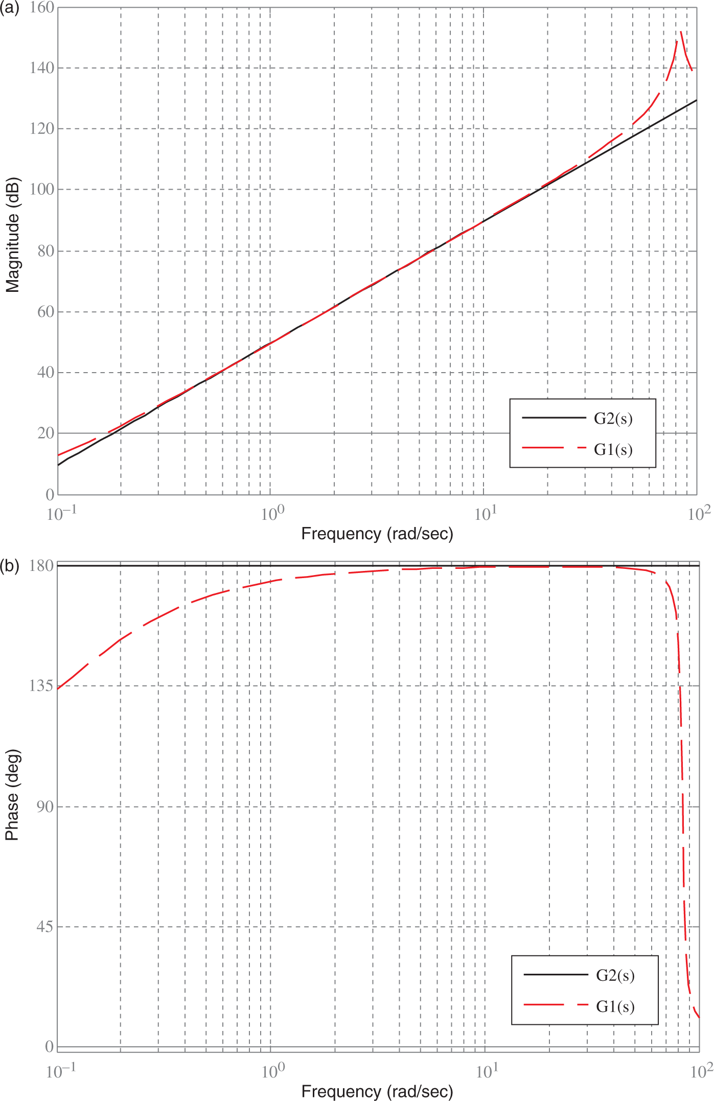
5. Conclusions
In this paper, the inverse screw transmission for two-terminal manipulation of a flywheel was adopted as a ground work for vibration suppression. The ideal dynamics model of the two-terminal flywheel is presented. The actual dynamics model of a two-terminal flywheel is also developed to incorporate the non-ideal factors, such as the structure mass, stiffness, viscousdamping, friction and backlash. The proposed two-terminal mechanism and the dynamics model are validated using a specifically designed prototype device. The experimental results indicate that the influence of the non-ideal factors is insignificant in the frequency range covering real applications though the effect is relatively larger in the lower and higher frequency bands.
The modeling and characterization results of the two-terminal flywheel in this part lay a solid foundation for applications in vehicle passive suspension, which will be described in detail later in Part II (Li et al., 2011b).
Footnotes
Acknowledgements
The authors would like to thank the anonymous reviewers for their valuable and detailed comments and suggestions.
Funding
This work was supported in part by the Natural Sciences and Engineering Research Council of Canada, National Natural Science Foundation of China (grant number 50905193), and Chongqing Municipal Science and Technology Commission Program (grant numbers 2010BB4249, 2010BB4261).