
Abstract
The proposed work presents a methodology to analyze the influence of lateral vibrations on the whirling characteristics of a rotor-bearing system. A complex variable approach, which is proposed for the analysis of a single rotor system, is very powerful for this purpose. The approach is expanded to the analysis of a combined rotor system to apply it to the gear system analysis. The bearing stiffness and shaft flexibility of the geared rotor system are taken into account in two ways. With regard to the rotor effect, the frequency response functions are obtained for both torsional motions and coupled lateral-torsional motions. By obtaining the differences in the frequency responses of both the models, the effect of neglecting rotor effects in gear dynamics simulation is studied. The lateral stiffness of the system, which reflects the shaft and bearing stiffness, is considered to make a strong lateral and torsional motion coupling. It is shown that the lateral vibrations have considerable effect when the natural frequencies of the lateral vibration and torsional vibration are close to each other, which is expected. The effect of lateral-torsional coupling on gear dynamics is discussed based on the response of the system.
Keywords
1. Introduction
Gear dynamic studies have usually neglected the lateral vibration of the shafts and bearings and have typically represented the system with a torsional model. Although neglecting torsional vibrations might provide a good approximation for systems that have shafts with small compliances, the dynamic coupling between the torsional and transverse vibrations due to gear mesh affects the system behavior considerably when the shafts have high compliances. Mitchell and Mellen (1975) included lateral vibration of the shafts and their bearings in their models. Lund (1978) included influence coefficients at each gear mesh by using the Holzer method for torsional vibrations and the Myklestad-prohl method for lateral vibrations, thus obtaining critical speeds and a forced vibration response.
It appears that the most common interests of reported works are on gear vibrations caused by backlash, deviation of tooth profile and eccentricities. The backlash detection and its influence in geared systems has been studied by Sarkar et al. (1997). They performed modeling, simulation and conducted experiments on geared systems to detect backlash. Ambili and Fregolent (1998) determined modal parameters of a spur gear system using the harmonic balance method. A pair of spur gears was considered in their analysis to predict vibrations due to gear tooth error. The design of compact spur gears taking into account the tooth stress and dynamic response was studied by Lin et al. (1998). The dynamic behavior of spur gears to varying mesh stiffness and tooth error has been studied by Kuan and Lin (2003). They considered the gear tooth mesh as a linear spring of variable stiffness and performed dynamic analysis to determine the response of the system. A mathematical model for gear geometry error and mounting error was developed by Velex and Maatar (1996). In their analysis, the influence of shape deviations and mounting errors on gear dynamic behavior was studied. Theodassiades and Nastiavas (2000) studied nonlinear behavior of a gear system with backlash and varying stiffness. They also studied nonlinear influence of bearing characteristics on a gear pair system (2001). A motor driven gear pair system was considered in their work for performing periodic and chaotic dynamics taking into account gear tooth backlash. Modal analysis of compliant multi-body gear systems has been analyzed by Vinayak and Singh (2005). Shen et al. (2007) performed coupled torsional–lateral vibration of the unbalanced rotor system with external excitations through numerical simulation. Two kinds of unbalance, namely static unbalance and dynamic unbalance, are considered in the rotor system. Coupled torsional and transverse vibration of a back-to-back gearbox rig was carried out by Sargeant et al. (2005). The coupled torsional and transverse vibration of a back-to-back gearbox system has been investigated experimentally and analytically. Receptance methods were used to model the system, and were shown to be effective. The paper presents the detailed results of a fulltorsional/transverse model analysis of the gearbox system by Sargeant et al. (2005).
In most of these studies interactions of the gear shafts and gear dynamics are not investigated in depth. A gear system can be viewed as a set of rotor systems interacting dynamically with one another. Therefore, linear as well as gyroscopic whirling phenomena are expected to exist in addition to vibrations caused by gear tooth, bearings and shaft interactions. The rotor effect is considered negligible in gear systems with bearing supports in both ends because design can be made to minimize lateral deflections; however it can be a significant effect in overhung gears, such as seen in hypoid gear systems.
Complex mode description was first proposed by Lee and his colleagues, who represented two-dimensional motion of rotors by using complex variables. The concept of directional frequency response function (dFRF) was also introduced by Lee and Lee (1994). Directional frequency response functions define the relationships between the forward and backward excitations and forward and backward responses, which reveals important information about rotor systems, for example the existence of anisotropy. A frequency domain diagnostic method of anisotropy and asymmetry in a rotor system using dFRFs obtained by complex modal testing has been suggested by Lee and Lee (1997). They also suggested the use of unidirectional random excitation techniques to estimate dFRFs. They studied the eigenvalues of a rotor shaft system with an asymmetrically placed rotor on elastic supports incorporating a gyroscopic effect. The complex variable description and directional modes have been redefined by Kessler and Kim (2002) in a much more intuitive manner. These authors defined the rotor model as a combination of the forward and backward sub-modes, and defined theforward mode as the mode whose forward sub-mode dominates, and the backward mode as the mode whose backward sub-mode dominates. Experimental verification of the simultaneous existence of forward and backward whirling in the rotor was carried out by Lee (1994), Kessler and Kim (2002), and Rao et al. (1996). Finite element analysis of a coupled lateral-torsional system has been done by Neriya et al. (1985), and modeling a gear system by a rotor system formulated in the finite element analysis was carried out by Kahraman et al. (1992).
2. Formulation and interpretation of problem
In many gear dynamics analyses, the effect of the lateral vibration has been ignored in modeling the system, with the underlying assumption that the effect of the lateral deflection in a typical gear system is negligible compared to that of the torsional deflection. This assumption may not be valid in some configurations such as overhung-type gears rotating at a high speed, in which the whirling resonance speed occurs within the operating frequency range. To understand the effect of possible interactions between the lateral and torsional responses, a simple gear system is considered in this study, whose parameters are chosen so that its lateral and torsional natural frequencies are close to each other.
2.1. Equation of motion in real description
The system consists of two gears (pinion, P and gear, G) in mesh and driven by a motor M and driving a load L. The shafts on which gears are mounted have two translational degrees-of-freedom each, one in a horizontal direction (Z direction) and the other in a vertical direction (Y direction). The gears, motor and load have torsional degree-of-freedom. Therefore, there are four degrees-of-freedom (xp, yp, xg, and yg) in the lateral direction and four degrees of system (θm, θp, θg, and θl) in the torsional direction in the system. The shaft stiffness (K1 for shaft 1 and K2 for shaft 2) is assumed to be constant in all directions, making the system isoparametric.
The equations of motion can be derived by using the Lagrange method.
The kinetic energy of the system T is
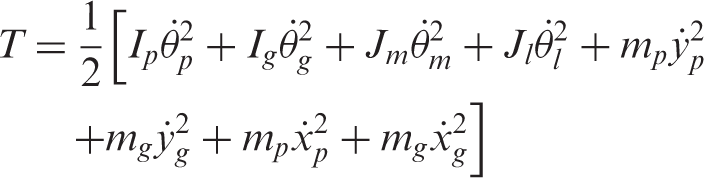
The strain energy of the system V is
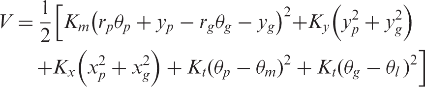
Lagrange equation states that
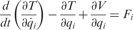
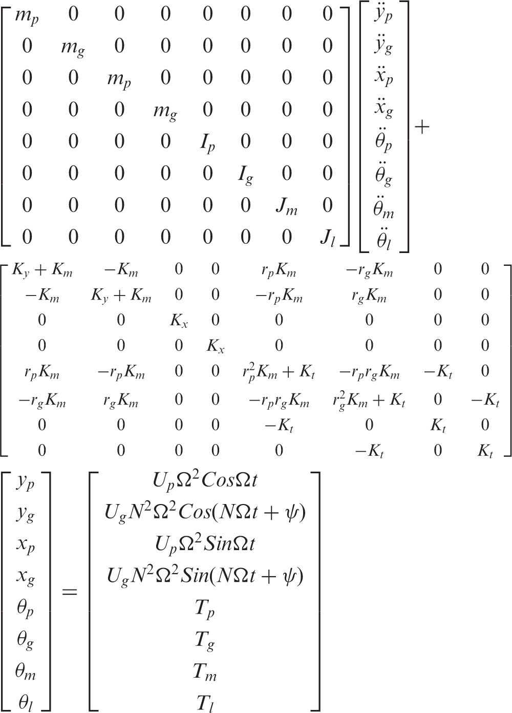
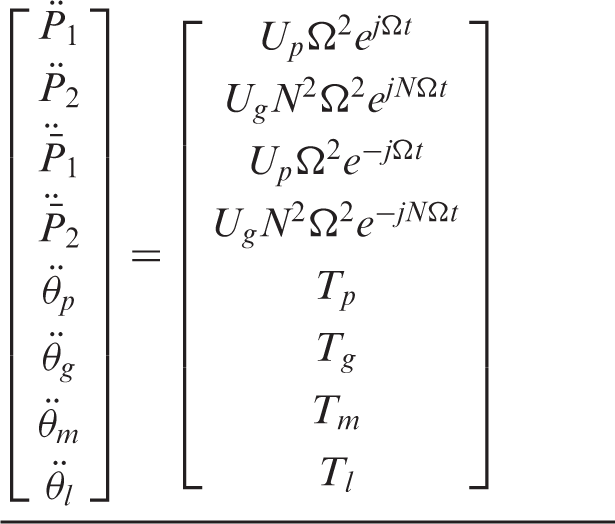
The external forces considered in the above equationare:
Torques on motor (Tm), load (Tl), pinion (Tp) and gear (Tg) Unbalance masses Up and Ug acting on pinion andgear respectively. ψ defines the phase angle between the two unbalance masses in the pinion and gear. These unbalance forces act in the lateral directions, however they can cause torsional responses because the equations are coupled in two directions.
2.2. Equation of motion in complex variable description
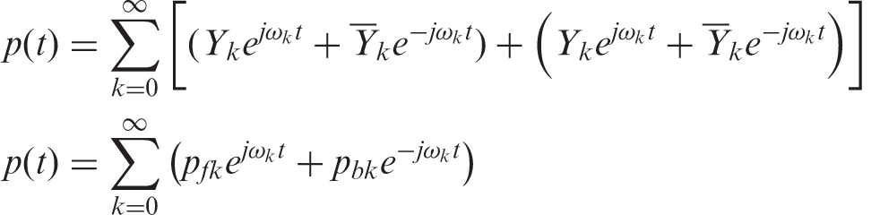
Any planar motions can be represented as complex variable of function of time by matching the real and imaginary parts of the complex variable to y and z coordinates. For example, any point P(t) in complex plane can be represented by vector:

Expanding y(t) and z(t) as Fourier series and collecting +ω and -ω terms, the above equation can be represented as:
To transform equation (4) to complex variable form following the procedure proposed by Kessler and Kim (2002), the displacement vector is transformed as follows.
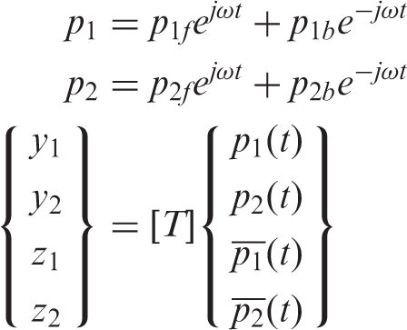
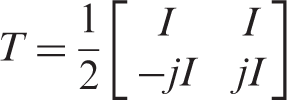
The equation of motion after transformation is:
Once the system equation is set up in this form, positive frequency solutions indicate whirling and rotational motion in the forward direction (counter-clockwise direction) and negative frequency solutions indicate motions in the backward direction (clockwise direction).
2.3. System parameters
The main purpose of this work is to understand the interaction between the lateral and torsional vibrations of gear systems in theoretical terms and the system parameters are chosen so that the lateral and torsional mode frequencies exist in a close range to induce relatively strong coupling effect.
Mass of pinion, mp = 16.96 kg
Mass of gear, mg = 5.65 kg
Mass Moment of Inertia for pinion, Ip = 0.0269 kg-m2
Mass Moment of Inertia for gear, Ig = 0.0291 kg-m2
Mass Moment of Inertia for motor, Jm = 0.459 kg-m2
Mass Moment of Inertia for load, Jl = 0.549 kg-m2
Mesh stiffness, Km = 2 x 10⁸ N-m
Torsional stiffness, Kt = 115 N-m/rad
Radius of pinion, rp = 0.0564 m
Radius of gear, rg = 0.1015 m
The gear ratio is given as 1.79 from the ratio of radiusof the gear and pinion. Also notice that Kt is taken as the same for the motor side shaft and the load side shaft.
3. Torsional vibration response of the gear system
First, we consider the torsional vibration of the system without considering the lateral vibration effect. The bearing stiffness can be set to an infinite value in both x and y directions to remove the lateral vibration effect in equation (4). Now the system becomes a four degree-of-freedom system. Equations of motion described in matrix form are:
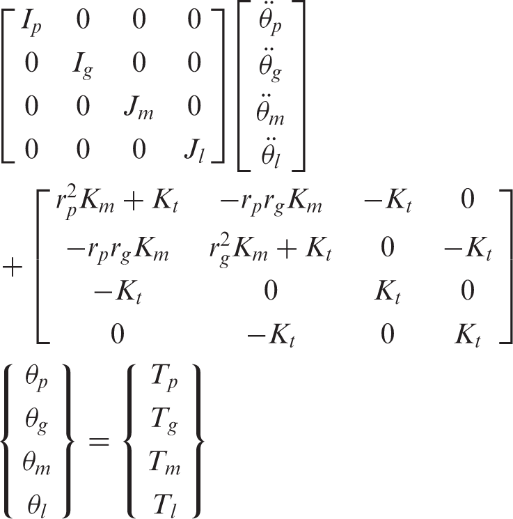
3.1. Free vibration analysis
For free vibration analysis, letting the external force vector be zero and assuming harmonic responses, the free vibration equation becomes:
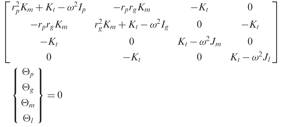
Natural frequencies of the system are obtained by solving the eigenvalues of the determinant of the above equation. The modal frequencies obtained as:
±0, ±14.8, ±66.6, ±9719.06 (rad/s).
Mode shapes after normalization for Θp

As expected, the first mode associated with the zero frequency is a rigid body mode. The mode shape of this mode indicates the gear ratio. From the mode shape, it is seen that the second mode is dominated by the motions of the motor and load relative to the pinion and gear, respectively. The third mode is dominated by the motions of the gear and pinion masses relative to each other. The highest mode is isolated vibration by the pinion and gear associated by the spring that represents the tooth stiffness.
4. Vibration of lateral-torsional gear model
4.1. Free vibration analysis
Free vibration analysis is conducted using the equation of motion described in real variables, which provides the same solutions. The solutions obtained from the real analysis can be transformed to the complex variable description using equation (9), which provides the directional information.
From the equation of motion in equation (4), letting the external force be zero and assuming harmonic responses
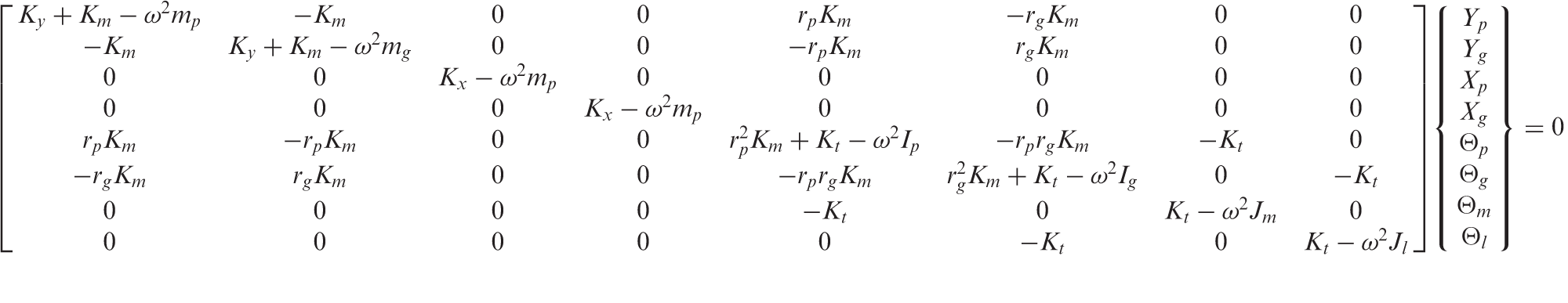
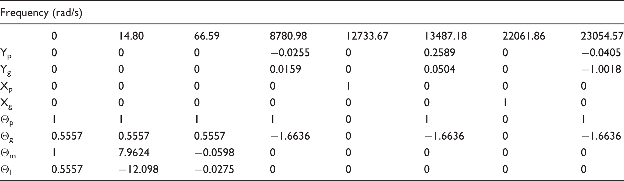
Solving for the eigenvalues and eigenvectors of the determinant in the above equation with the physical parameters, the natural frequencies are obtained as:
Mode shapes after normalization for θp
The system equation is an eight by eight equation; therefore eight modes are obtained. There are four lateral modes and four torsional modes. As before, the first frequency of vibration is zero, which corresponds to the rigid body torsional mode.
The second and third modes are torsional modes without any participation by lateral motion modes. The second mode is predominantly the relative motion of the motor and load, and the third mode is predominantly the relative motion between the pinion-gear set and the motor-load set. The relative motion between the pinion and gear is not involved in this motion as the pinion-gear set moves without inducing any deformation in the gear teeth mesh.
The fifth and seventh modes are uncoupled lateral modes in the x-direction, which represent the single degree-of-freedom motions of the gear and pinion respectively. Modes four, six and eight are the modes with coupling effect between the lateral and torsional modes. The fourth mode shows the weakest coupling.
Mathematical model of the geared rotor system.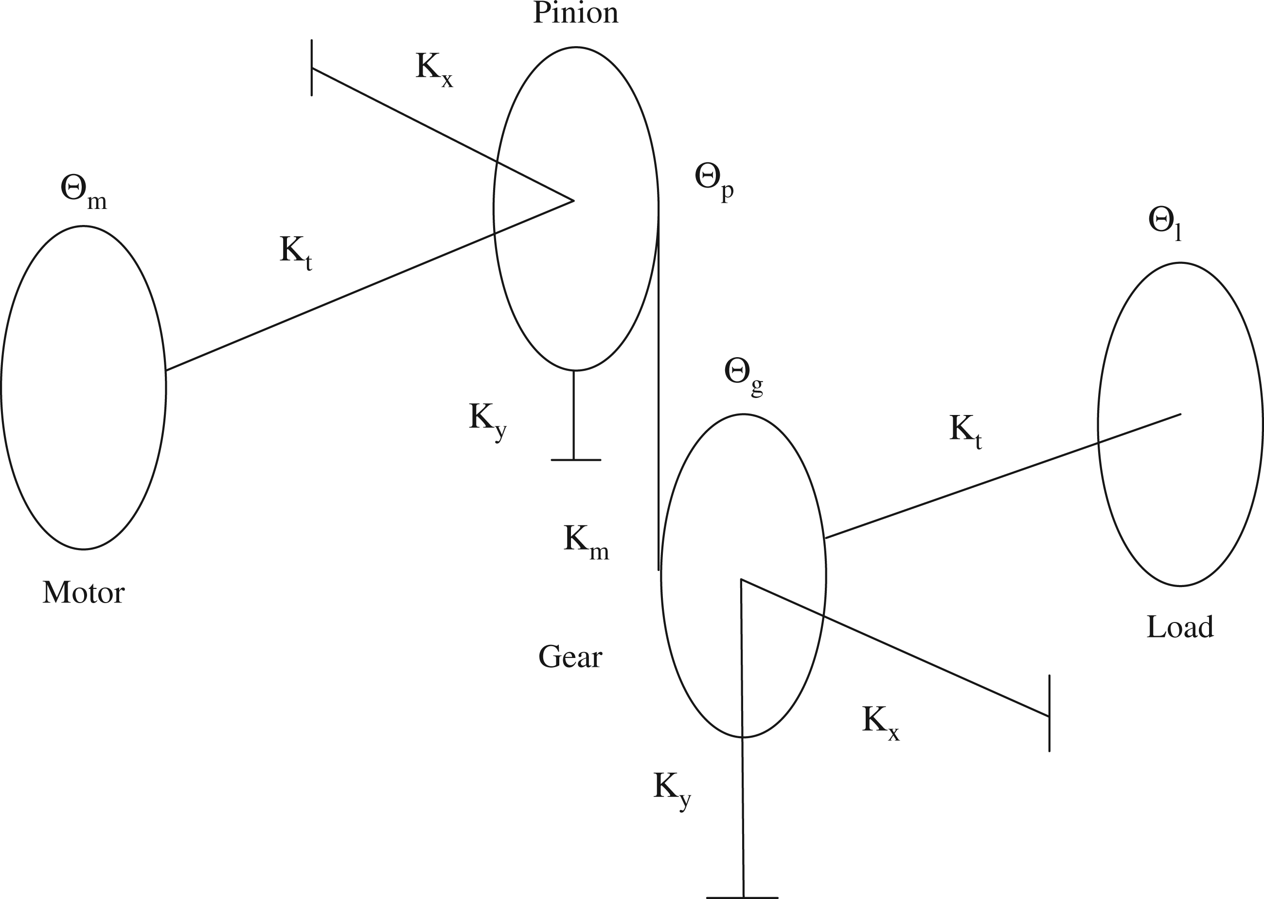
As can be seen from the table, the lateral modes are active only at very high frequencies. For all lower frequencies, their mode participations are nearly zero, which suggest they can be safely ignored. The first three lower frequency modes are purely torsional modes. The higher frequency modes are bending-torsion combined modes with two in-between frequency modes being purely transverse. For these purely transverse modes, the displacement occurs in the direction perpendicular to the mesh line. Along the mesh line (Ydirection) where coupling is present, no displacement occurs. For the system under consideration, if only torsional analysis had been carried out, the lateral motions would have been ignored; therefore only the first three modes would have been picked up by the analysis. As the frequency increases, the lateral modes become more and more significant.
If we compare the above modes to the torsional-only system, it can be seen that the first three modes are almost the same in both systems, even though the third modal frequency is different because the action of the lateral spring provides extra stiffness in this torsional mode. These three motions are not of major concern in gear dynamics because they involve rigid body relative motions of the gear-pinion set.
5. Summary and conclusion
In the present work, vibration analysis of a geared rotorsystem has been carried out for combined torsional-lateral motions. The gear-pinion system is modeled as a combined rotor system in the lateral directions and a torsional system is driven by a motor and driving a load inertia in the rotationary direction. The equations of motion for an eight degrees-of-freedom gear system are derived using Lagrange’s equation and converted to complex variable form using the method developed by Kessler and Kim (2002). The complex variable notation helps in understanding the whirling characteristics of rotor systems in a more simple way. Initially the system model that considered only the torsional motion was analyzed, and then the results were later compared with the responses obtained by solving for the combined torsional-lateral system. The combined system has been analyzed in two different forms: one in the real co-ordinates description to compare it with the torsion-only system, and the other in the complex co-ordinates description to understand the directional information of the whirling motion of the system. It has been demonstrated that the lateral motions interact significantly with torsional degrees-of-freedom if the resonance frequencies are similar. For the system under consideration, this interaction occurs around 13,000 rad/s where two close critical speeds exist instead of one as found by the torsional-only system. If the operating speed were around 22,000 rad/s, two more critical speeds exist at 22,062 rad/s and 23,054 rad/s which otherwise would have been ignored. The analysis certainly shows that the lateral whirling motions of the rotors and the torsional motions of the gears interact with each other. The degree of interaction depends on the proximity of the natural frequencies of the lateral and torsional motions. Neglecting the coupled effect in design can have serious effects on the estimation of the performance of the system if their frequencies are close to one another.
Footnotes
Funding
This research received no specific grant from any funding agency in the public, commercial, or not-for-profit sectors.