






Abstract
Brushless direct current (BLDC) motors are widely used in industrial, aerospace, medical, machine tools, aerospace and control applications. Nowadays they are becoming popular due to their advantages such as reduced maintenance, better speed-torque characteristics, good dynamic performance, noiseless operation, wide speed range, compact size, high torque to volume ratio, low moment of inertia and high efficiency. However, very few control techniques are available for controlling the BLDC drive systems. This paper presents a MATLAB simulation of practically realizable control techniques such as a conventional proportional-integral-derivative (PID) controller, a fuzzy controller, an adaptive artificial neural network proportional-integral-derivative (ANN-PID) controller and a pulse width modulation technique based PID controller for achieving better performance during the operating conditions. The simulation results are presented to highlight the effectiveness of these controllers such as speed of response, overshoot and steady-state error etc.
1. Introduction
In recent years, brushless direct current (BLDC) motors became popular in various applications due to their superior speed-torque characteristics, high efficiency, less maintenance, and wide operating speed range (Miller, 1989). In high performance drive applications such as robotics, spacecrafts, machine tools, medical applications etc., an accurate speed or position control is of greater importance. In such applications, the control of the BLDC motor drive system demands special attention because it should provide a faster response, quickly recover from load impact and be insensitive to parameter variations. A conventional controller like the proportional-integral-derivative (PID) controller requires an accurate mathematical model describing the system, but practically obtaining the exact mathematical model is a cumbersome process (Weerasooriya and El-Sharkavi, 1991). In recent years, many control techniques have been introduced in the modern drive systems using PID controllers (Wu et al., 2005; Bagis, 2007), neural networks (Narendra and Parthasarathy, 1990; Rahman and Hoque, 1997; Lee and Teng, 2000; Rubaai et al., 2000), an adaptive controller using particle swarm optimization algorithm and a neuro-fuzzy controller (Rubaai et al., 2002; Awadallah et al., 2009), a multi-layer artificial neural network (Weerasooriya and El-Sharkavi, 1991; El-Sharkawi et al., 1994), hybrid controllers (Rubaai et al., 2001, 2008), fuzzy logic controller (FLC) (Shanmugasundram et al., 2009a; Rajan et al., 2010) and compensator (Shanmugasundram et al., 2008). These control techniques are usually based on system model parameters. If a PID controller is used in conjunction with the pulse width modulation (PWM) technique (Miller, 1989; Kun et al., 2004; Hemanand and Rajesh, 2006; Shanmugasundram et al., 2009b) the overall efficiency and controllability can be improved and implemented using inexpensive PIC microcontrollers, digital signal processors etc. An extremely powerful artificial neural network (ANN) such as multilayer feed-forward neural networks (FFNNs) and FLCs are receiving wide attention in control applications. An ANN resembles a biological neuron structure and it can be trained with training data to acquire knowledge. When used in real time as a motor controller, an ANN can instruct the system to perform in a desired manner. The ANN provides a nonlinear mapping between the inputs and outputs of a BLDC motor drive system, without the knowledge of any predetermined mathematical model of the system. Similarly, fuzzy logic control (FLC) has found extensive use in the motion control applications and has attracted the growing attention and interest of many researchers due to the simplicity in implementation by creating a knowledge base from the known behavior of the system without obtaining a mathematical model of the system. Moreover, the FLC can greatly reduce the effects of nonlinearity on the BLDC motor drive systems. Therefore, the use of ANN and FLC can make the system robust, efficient, and immune to undesired operating conditions and nonlinearities present in the system.
In the proposed work, modeling of the BLDC motor drive system and simulation of BLDC motor drive system with various practically feasible controllers such as PID control, PID control integrated with PWM technique, FLC, and adaptive ANN-PID control are presented. The performances of these controllers are evaluated at different operating conditions such as load impact, parameter variations, change in reference speed etc.
2. Modeling of brushless drive system
An important step in the design of controllers for control systems is to obtain the exact mathematical model of the system which can produce output responses similar to those produced by the actual system. However, due to the complexity of the system, development of exact mathematical models is practically infeasible. Therefore, in order to design practically realizable controllers, a simplified model of the system should be developed to produce responses similar to those of actual system. The schematic of the electromechanical system consisting of a brushless DC motor, driver circuit, inverter and mechanical load is shown in Figure 1.
Schematic of electromechanical system.
The system model is developed considering armature voltage and external load torque as two inputs, and angular velocity as a single output (Campa et al., 2008; Kapun et al., 2008; Shanmugasundram et al., 2009b). In order simplify the model, all the stator phase windings are assumed to have equal resistance per phase and constant self and mutual inductances, iron loss is negligible, motor flux is unsaturated and power semiconductor devices are ideal. Also it is assumed that at any instant only two phase windings conduct current. The following linear equations describing the system behavior can be represented as,


The phase currents, phase voltages and phase back-emfs are assumed to be equal. The total resistance opposing the phase current will be twice the resistance per phase.


Since the torque developed by the motor is proportional to the current, the torque equation can be expressed as,

Since the sum of all the opposing torques due to mechanical elements of motor and load torque is equal to the torque developed by the motor, the torque equation can be written as,


The torque equation in terms of phase back-emfs and phase currents is given by,

The following transfer functions (15)–(18) represent the relationship between input and output of the various blocks in the block diagram shown in Figure 2.
Block diagram of brushless direct current motor drive system.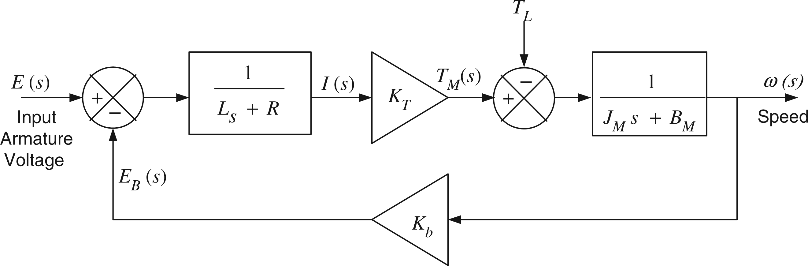


3. Proportional-integral-derivative controller for brushless direct current drive
Conventional controllers have been used to improve the performance of the industrial control systems over the past few decades. The major challenge for the expert designing the PID controller is to obtain the exact mathematical model of the system and tuning parameters of the PID controller by applying well known tuning methods. Finally, the tuning parameters are fine tuned to obtain a satisfactory performance under the operating conditions. The PID controllers are most suited for control systems with fixed system dynamics and no parameter variations during the operating conditions. The PID controller can be easily implemented for the BLDC motor drive system to improve its performance.
The PID control algorithm considered for simulation is given by,

The corresponding transfer function is given by,
Step change in load from no load to full load (0.42 N.m) at rated angular velocity of 420 rad/s. Step change in angular velocity from 420 rad/s to 210 rad/s and then to 420 rad/s at full load (0.42 N.m). Step change in angular velocity from 420 rad/s to 210 rad/s and then to 420 rad/s at no load (0.042 N.m). Simulink model of the brushless direct current motor drive system with proportional-integral-derivative controller.
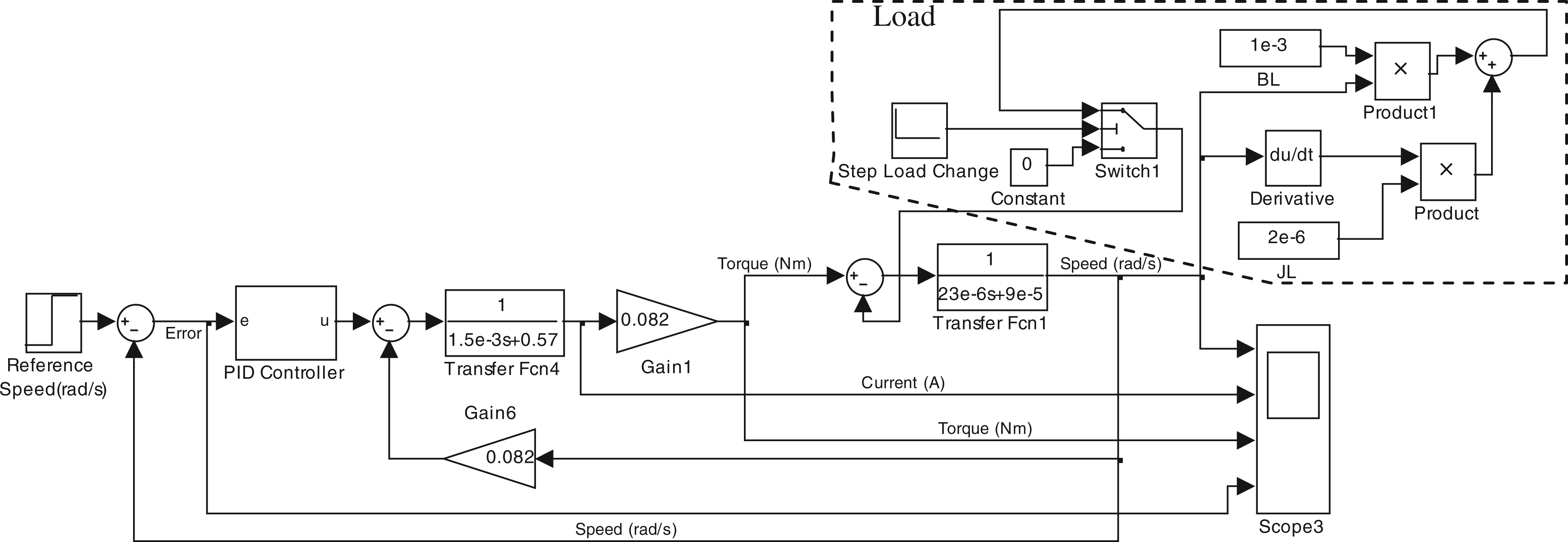

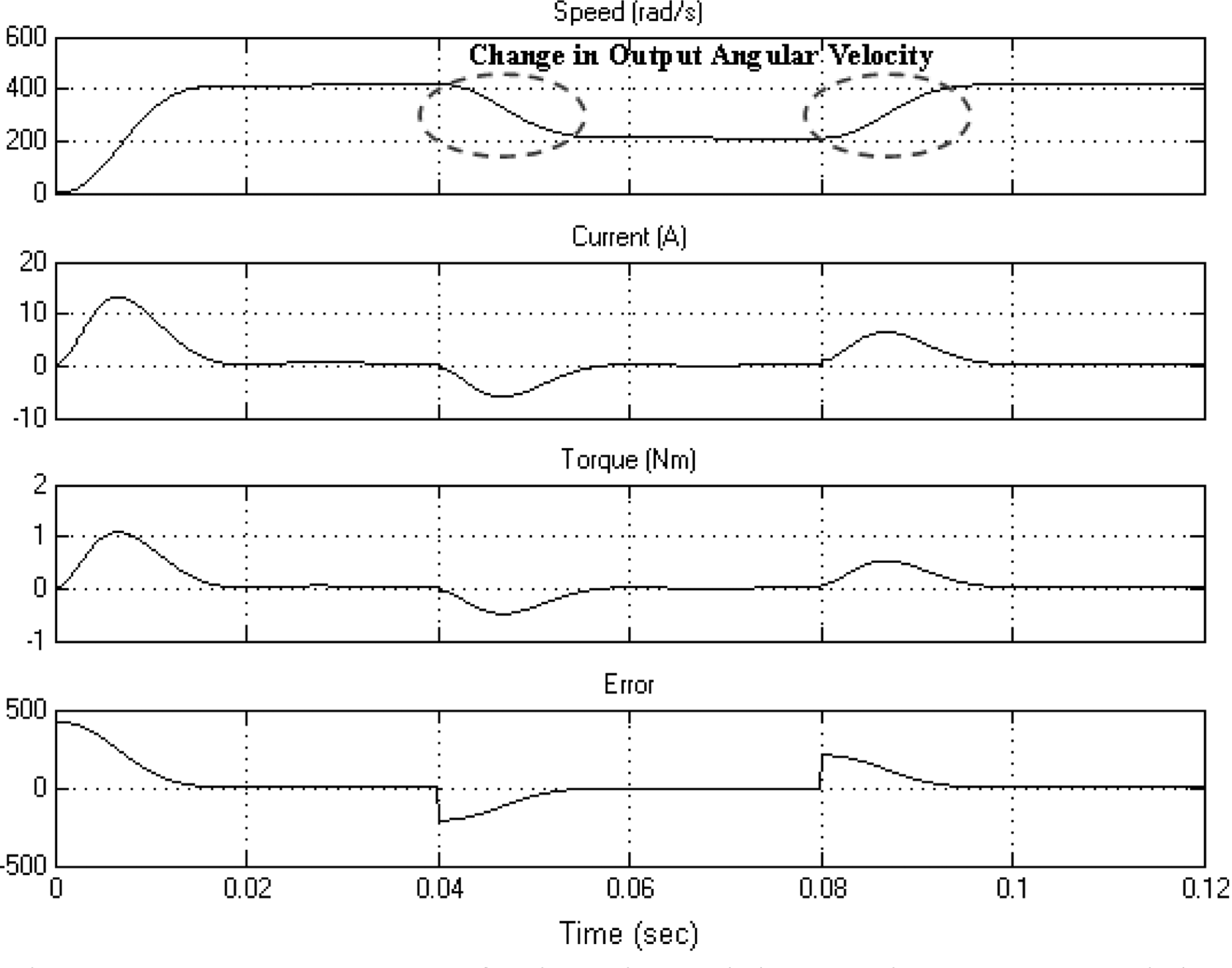
The responses for the above mentioned three operating conditions are shown in Figures 4 to 6. The PID controller is found to be capable of eliminating steady state error due to integral action and track the output changes due to the derivative action. When full load [JL = 23e-6 kg-m2 and BL = 1e-3 N.m/(rad/s)] is applied at 0.05 s, the output angular velocity momentarily drops but it reaches steady value quickly within 0.01 s. Moreover, it is found that when the reference angular velocity is changed at full load or no load, the PID controller is able to track the change in output angular velocity quickly. The performance parameters are given in Table 2.
Responses of the brushless direct current motor drive system due to step change in load at 0.05 s from no load to full load (0.42 N.m). Responses of the brushless direct current motor drive system due to step change in reference angular velocity from 420 rad/s to 210 rad/s at 0.04 sec and vice versa at 0.08 s without load. Responses of the brushless direct current motor drive system due to step change in reference angular velocity from 420 rad/s to 210 rad/s at 0.04 s and vice versa at 0.08 s with full load (0.42 N.m).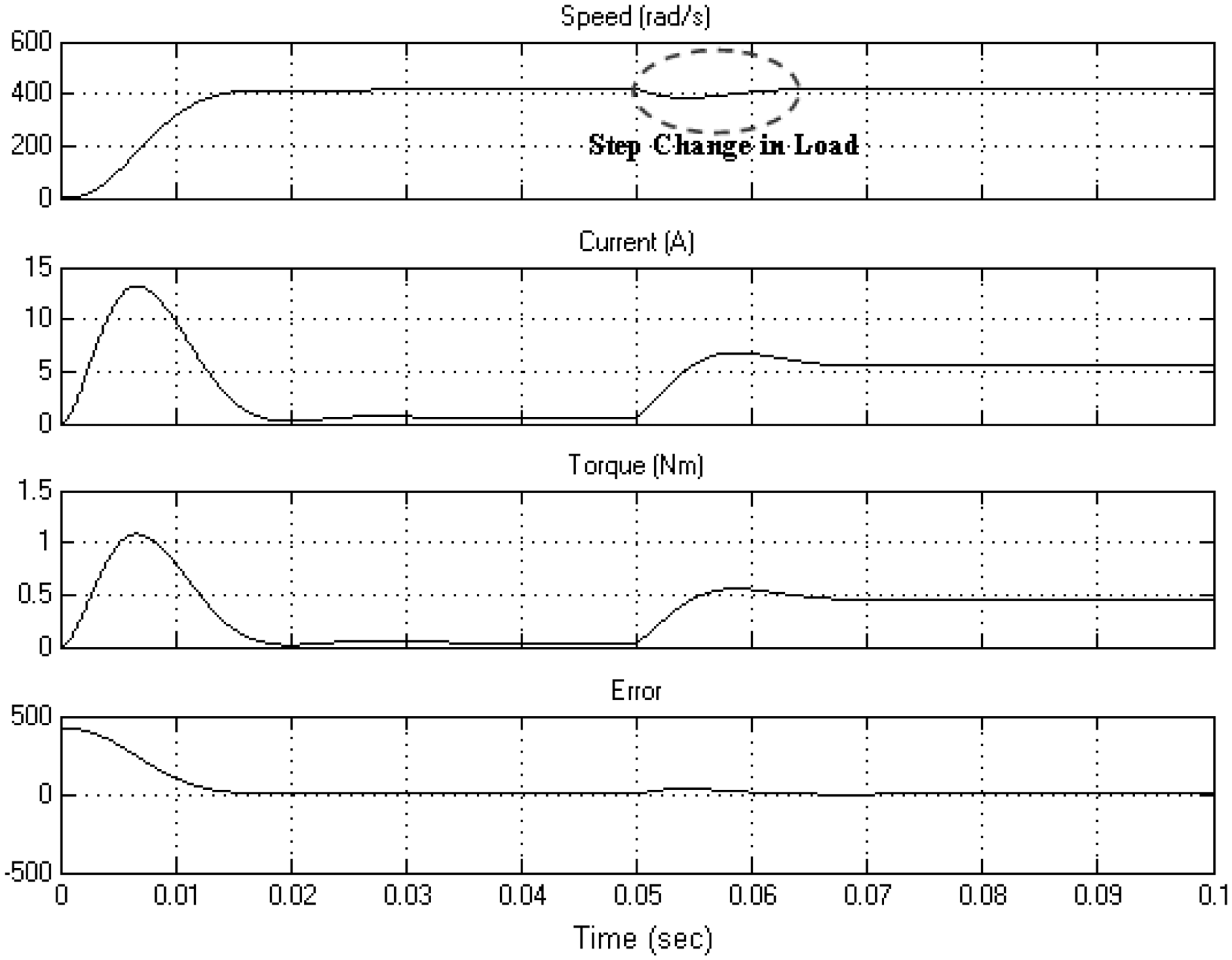

4. Fuzzy logic controller for brushless direct current drive
FLC is one of the advanced control techniques applied for the nonlinear and complex industrial control systems (Rubaai et al., 2001, 2002, 2008; Shanmugasundram et al., 2009a) whose mathematical models are unpredictable. However, it has its own advantages and limitations. An FLC can be easily designed for any system if the designer has the knowledge about the behavior of the system under various operating conditions. The designer has to acquire knowledge from the skilled technicians or operators handling the system. This knowledge is encoded in the form of IF-THEN fuzzy rules to form rule base. FLC design shown in Figure 7 involves three processes, namely fuzzification, inference and defuzzification. In the fuzzification process, the real value crisp inputs are converted into fuzzy values and in the inference process, the rules are evaluated based on the fuzzy inputs to obtain output fuzzy sets. The fuzzy membership functions are used as tools to convert crisp values into fuzzy linguistic values. Finally, in the defuzzification process, all the output fuzzy sets are aggregated and crisp output is obtained by applying any one of the defuzzification methods.
Block diagram of fuzzy logic controller.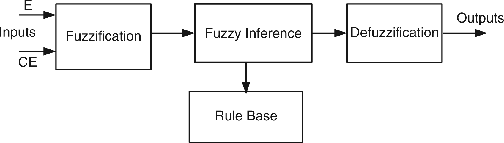
An FLC designed for the BLDC motor drive system has two inputs “error” and “rate of change in error”, and one output “voltage”. The error, E is defined as the difference between reference velocity and actual velocity and the rate of change in error, CE is defined as difference between present error e(k) and previous error e(k − 1).


The fuzzy variables error, rate of change in error and voltage are quantized into the following linguistic terms, Negative (N), Positive (P) and No-Change (NC) or Zero (Z). The designer can choose any shape for the membership functions based on the preference and experience. The triangular membership functions chosen for the input and output variables are shown in Figure 8.
Membership functions of error, change in error and voltage.
The range for error, rate of change in error and voltage is decided based on the information gathered from the PID controller based BLDC motor drive system. The Simulink model for the BLDC motor drive system with FLC is shown in Figure 9. The set of IF-THEN rules framed based on the experience and knowledge about the behavior of the system are given below,
Simulink model of brushless direct current drive system with fuzzy logic controller.
R1. If (Error is NE) and (Change-in-Error is NCE) then (Voltage is NV)
R2. If (Error is NE) and (Change-in-Error is ZCE) then (Voltage is NV)
R3. If (Error is NE) and (Change-in-Error is PCE) then (Voltage is NV)
R4. If (Error is ZE) and (Change-in-Error is NCE) then (Voltage is NV)
R5. If (Error is ZE) and (Change-in-Error is ZCE) then (Voltage is NC)
R6. If (Error is ZE) and (Change-in-Error is PCE) then (Voltage is PV)
R7. If (Error is PE) and (Change-in-Error is NCE) then (Voltage is PV)
R8. If (Error is PE) and (Change-in-Error is ZCE) then (Voltage is PV)
R9. If (Error is PE) and (Change-in-Error is PCE) then (Voltage is PV)
The fuzzy associative matrix that maps antecedents to consequents is shown in Table 1. The surface viewer shown in Figure 10 shows the dependency of output on the two inputs, i.e., it generates and plots an output surface map for the system. The formula for the centroid defuzzification method used in the simulation is given by,
Surface viewer. 3 × 3 FAM matrix FAM: fuzzy associative memory. Performance parameters of different controllers ANN-PID: artificial neural network proportional-integral-derivative. PID: proportional-integral-derivative. PWM: pulse width modulation.


The performance of the system has been improved by fine tuning the shape of the membership functions.
The performance of brushless drive system with FLC is examined for the following three operating conditions.
Step change in load from no load to full load (0.42 N.m) at rated angular velocity of 420 rad/s. Step change in angular velocity from 420 rad/s to 210 rad/s and then to 420 rad/s at full load (0.42 N.m). Step change in angular velocity from 420 rad/s to 210 rad/s and then to 420 rad/s at no load (0.042 N.m).
The responses obtained for the above mentioned operating conditions are shown in Figures 11 to 13. It is found that the FLC tracks the error and takes necessary control action. The system responses have better rise and settling times with no overshoot, steady-state error. The performance parameters are given in Table 2.
Responses of the brushless direct current motor drive system due to step change in load at 0.3 s from no load to full load (0.42 N.m) and vice versa at 0.6 s. Responses of the brushless direct current motor drive system due to step change in reference angular velocity from 420 rad/s to 210 rad/s at 0.3 s and vice versa at 0.6 s with full load. Responses of the brushless direct current motor drive system due to step change in reference angular velocity from 420 rad/s to 210 rad/s at 0.3 s and vice versa at 0.6 s without load.


5. Adaptive artificial neural network - proportional-integral- derivative controller for brushless direct current motor drive
There has been a growing demand in recent years for adaptive controllers in control applications. The main advantage of adaptive controllers is that they can adapt themselves according to the change in environments or operating conditions. For the systems with uncertainty, parameter variations and change in system dynamics, the conventional PID controller may not yield a better response for different operating conditions because the gain parameters are already tuned for a particular system dynamics. This problem can be overcome by replacing the conventional PID controller with an adaptive ANN-PID controller. The main objective of this control system is to generate the proper terminal voltage for the BLDC motor, so that the motor can track the reference speed Control structure for adaptive artificial neural network proportional-integral-derivative controller.
The feed forward ANN of size (3 × 3 × 3) as shown in Figure 15 is constructed with one input “Torque (T)” and three outputs “Proportional Gain kp”, “Integral Gain, ki” and “Derivative Gain, kd”. The network consists of one input layer with one neuron, three hidden layers each with three neurons and one output layer with three neurons. The function of each neuron is to compute the weighted sum of inputs and to perform the nonlinear sigmoidal or linear function on this sum.
Feed forward artificial neural network.
The FFNN is trained off-line using the error back propagation training algorithm to learn and compute “Proportional Gain kp”, “Integral Gain, ki” and “Derivative Gain, kd” for the given torque (T) input. The training data is obtained by computing torque for different values of moment of inertia (J) and viscous friction coefficient (B) and tuning the PID controller gains [22] for better transient and steady state responses. During training the weights and biases of the network are iteratively adjusted to minimize the mean square error and the network weights and biases are moved in the direction in which the performance function decreases most rapidly, i.e. the negative of the gradient. There are two different ways in which this gradient descent algorithm can be implemented: incremental mode and batch mode. In incremental mode, the gradient is computed and the weights are updated after each input is applied to the network. In batch mode, all the inputs are applied to the network before the weights are updated.
The training data comprises ten sets of data with target (t) and input (p). The target (t) represents “Proportional Gain kp”, “Integral Gain, ki” and “Derivative Gain, kd” for the given input (p) that represents torque (T). The bipolar continuous activation “tansig” is used for all the neurons in the input, hidden and output layers.
The plots shown in Figure 16 are drawn between input “p” and target “t” and between input “p” and the corresponding neural network output “y” with final weights and biases to test the learning capacity of the neural network. It is found that the plots are closely matching which is an indication that the neural network is well trained and able to provide desired target (t) i.e. “Proportional Gain kp”, “Integral Gain, ki” and “Derivative Gain, kd” for the input (p) which represents torque.
Performance of the trained neural network.
The Simulink model for the BLDC drive system with FLC is shown in Figure 17.
Simulink model of brushless direct current drive system with adaptive artificial neural network proportional-integral-derivative controller.
Whenever the load changes, the load torque input to the neural network also changes and as a result the neural network computes the desired gain parameters for the PID controller so as to improve the performance of the system.
The performance of brushless drive system with the adaptive ANN-PID controller is examined for the following two operating conditions.
Step change in load from full load (0.42 N.m) to no load at rated angular velocity of 420 rad/s. Step change in load from no load to full load (0.42 N.m) and step change in angular velocity from 420 rad/s to 210 rad/s.
The responses obtained for the above mentioned operating conditions are shown in Figures 18 to 19. It is found that the neural network provides gain parameters for the PID controller according to the change in load torque. The PID controller tracks the change in error and takes necessary control action. The system response exhibits slight overshoot when there is a change in load, but the system responds faster and reaches steady value without any steady state error. The performance parameters are given in Table 2.
Responses of the brushless direct current motor drive system due to step change in load from full load (0.42 N.m) to no load at rated angular velocity of 420 rad/s. Responses of the brushless direct current motor drive system due to step change in load from no load to full load (0.42 N.m) and step change in angular velocity from 420 rad/s to 210 rad/s at 0.05 s.

6. Pulse width modulation based proportional-integral-derivative controller for brushless direct current motor drive
The PWM technique is one of the popular control techniques used in practical control systems. It is mainly useful for controlling the input of the system according to the controller output. It is an efficient method as compared to the conventional methods because there is no wastage of power in the control elements and can be easily implemented and smoothly controlled by digital controllers such as DSPs and PIC microcontrollers. In the PWM technique, power semiconductor devices are turned ON and OFF for the required duty-cycle in order to control applied voltage and hence the input power supplied to the system. In the Simulink model shown in Figure 20, the PID controller output is used to control the duty-cycle of gating signal of the IGBTs, hence the input voltage applied to the BLDC motor so as to achieve better control action.
Simulink model of brushless direct current motor drive system with pulse width modulation based proportional-integral-derivative controller.
The performance of the brushless drive system with a PWM based PID controller is examined for the step change in load from no load to full load (0.42 N.m) at rated angular velocity of 420 rad/s. The responses of the system are shown in Figures 21 and 22. It is found that the BLDC motor drive system responds faster and reaches the steady state without any steady state error and oscillations. The performance parameters are given in Table 2.
Responses of the brushless direct current motor drive system due to step change in load at 0.05 s from no load to full load (0.42 N.m). Responses [top to bottom: speed, sawtooth wave, proportional-integral-derivative controller output control signal, pulse width modulation signal] of the brushless direct current (DC) motor drive system due to the step change in load at 0.05 s from no load to full load (0.42 N.m).

7. Conclusions
The MATLAB simulation for practically realizable control techniques like conventional PID controller, FLC, adaptive-PID controller and PWM based PID controller is carried out for different operating conditions and results are investigated. The performance parameters are listed in Table 2. It is found that the performance parameters such as rise time and settling time are slightly higher for the fuzzy and PWM based PID controllers. However, these controllers can be easily implemented in digital processors like DSPs and PIC microcontrollers. The adaptive ANN-PID controller can be used instead of conventional PID controller for applications where the system dynamics is likely to change during operating conditions. The experimental set-up is being created to implement these controllers and validate the experimental results with the simulation results.
Footnotes
Funding
We would like to thank the management, principal and head of the department of Sri Ramakrishna Engineering College and Jawaharlal Nehru Technological University, Hyderabad for providing facilities and valuable support for carrying out this work.
Notation
Parameters of brushless DC motor 36 V 5A 4 3 4000 RPM 0.42 Nm 0.082 N.m/A 1.25 kg 23 e-06 kg-m2 0.57 Ω 1.5 mH