
Abstract
This paper proposes a method of optimizing the cushion properties for a certain amphibious aircraft landing gear, which is establishing an accurate simulation model in least mean square by adjusting parameters. First, carry out a drop test under initial parameters to get the friction between the tire and platform, and the elastic parameters of the wheel to simulate the interactions of components. Second, repeatedly modify the model by analyzing the results of comparisons between the drop test and simulation until an accurate model with optimal parameters is established. Finally, verify that the cushion properties of the landing gear with the optimal parameters meet the requirements of airworthiness rules and the properties are greatly improved. The study shows that an adjusting-parameter drop test for establishing a simulation model is an available and reliable way to optimize the cushion properties of an amphibious aircraft landing gear.
1. Introduction
Landing gear plays a vital role in developing a new aircraft and ensures that the aircraft has enough safety and maneuverability at gliding, taking-off and landing. At touch down during landing, dynamic loads applied on the landing gear are mainly undertaken by shock absorbers, and are then of great interest in the design process of the shock absorber, as an influencing factor of structure damages (Aviation Industry, 2002).
So how to make a shock absorber have optimal cushion properties is a concern in design. Some relevant researches have been conducted to investigate the impact process and cushion properties of landing gear. Milwitzky and Cook (1724) studied theoretically the behavioral analysis of landing gear in the process of touch down. William and McGehee (1991) did a drop test for landing gear to research the cushion properties. Daugherty and Vogler (1990) researched the property control of F-106B airplane landing gear through a drop test. Along with the rapid development of computer technology, virtual prototype technology emerged. Thus, some researchers (Kruger, 2002; Maemori et al., 2003; Lernbeiss and Plöchl, 2007; Kruger and Morandini, 2011) widely used a method of simulation to analyze the properties of landing gear. However, a study of optimizing cushion properties of landing gear has not been done with the comprehensive consideration of a simulation and verification test.
Therefore, this paper aims to establish a complete methodology of optimization for the cushion properties of certain amphibious aircraft landing gear, including a simulation and verification test. In the process of simulating, it is necessary to modify the model of landing gear by adjusting parameters such as filling parameters (James, 1951) and diameters of the oil holes to obtain the accurate model for optimizing the cushion properties. It must be verified that the optimized property indexes satisfy those of airworthiness rules (Wang and Li, 2010).
2. Drop test under initial parameters
2.1. Testing equipment
The test rig used in this article is designed for a free drop test on light aircraft landing gear. It is vertical in style, consisting of column, slide way, lift motor, wheel turning speed system, impact platform and clamp of test pieces, shown in Figure 1. The impact platform supports the impulsive force when the landing gear drops, and provides the friction of tires and the ground. The frictional coefficient can be changed through adjusting the layout pattern of the platform.
Drop test rig for landing gear.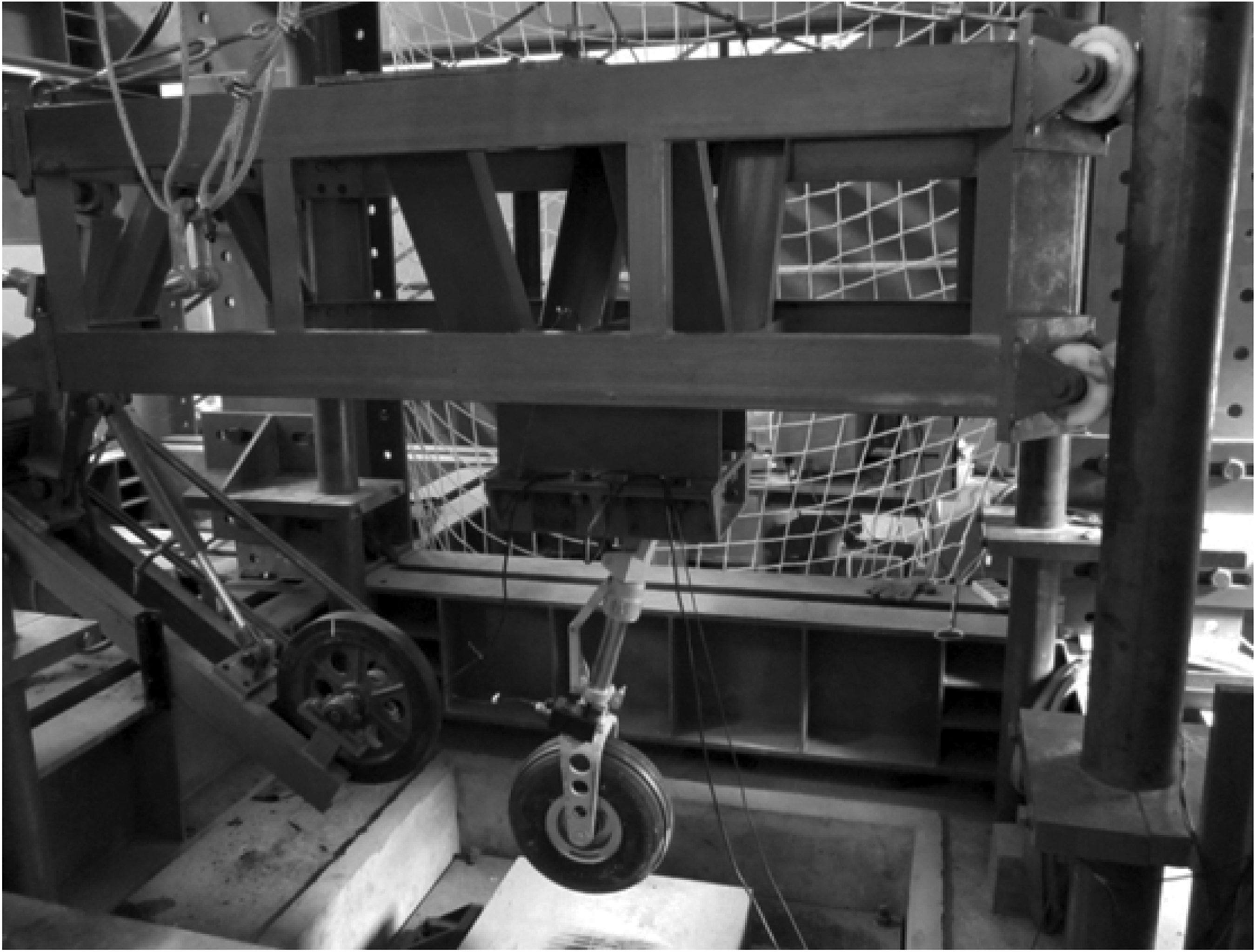
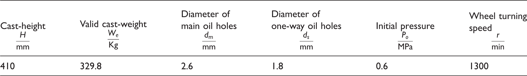
Initial cast-parameters of drop test


2.2. Results of test
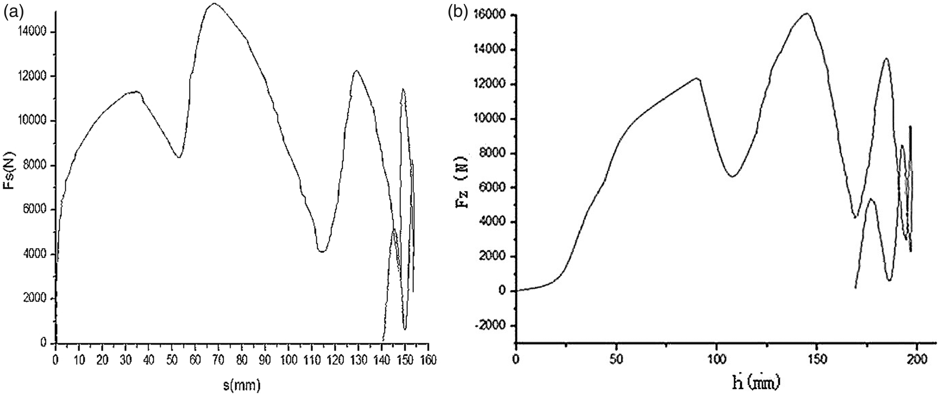
It is necessary to deal with the sensor data gained by a measurement system, thus getting the parameters to justify the cushion properties of the shock absorber. Here are some equations presenting relations between test parameters, shown as equations (1) to (5).
2.2.1. Vertical load of wheel

Where FZ is the vertical load, from the curve of which can be obtained the maximum
2.2.2. Absorbing energy of absorber system Ac
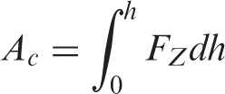
Where h is the cast-height. The data of
2.2.3. Absorbing energy of shock absorber
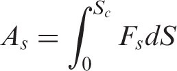
Where Sc is the maximum stroke of shock absorber,
2.2.4. Efficiency coefficients of absorber system and shock absorber, η and
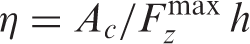
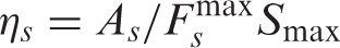
Where
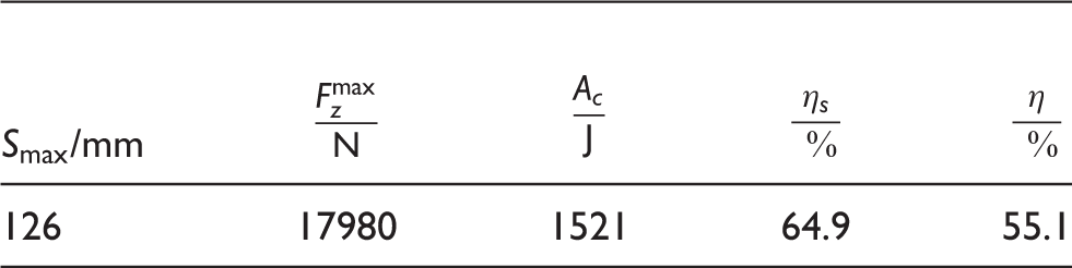
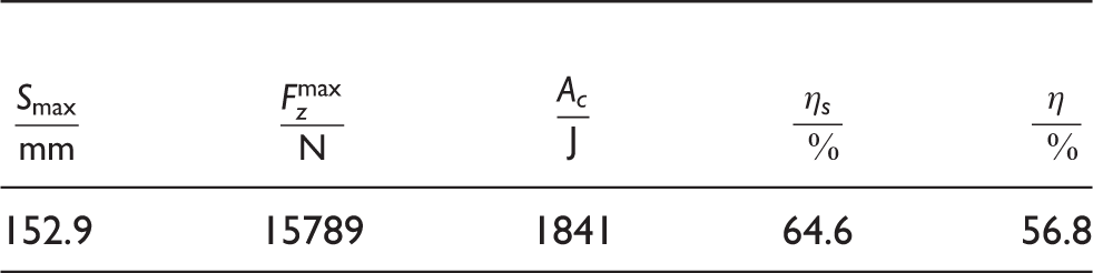
Calculate the formulas above by using the initial experimental data, thus listing some parameters measuring properties in Table 2 and describing the absorbing energy curves of the shock absorber and absorber system shown in Figure 2.
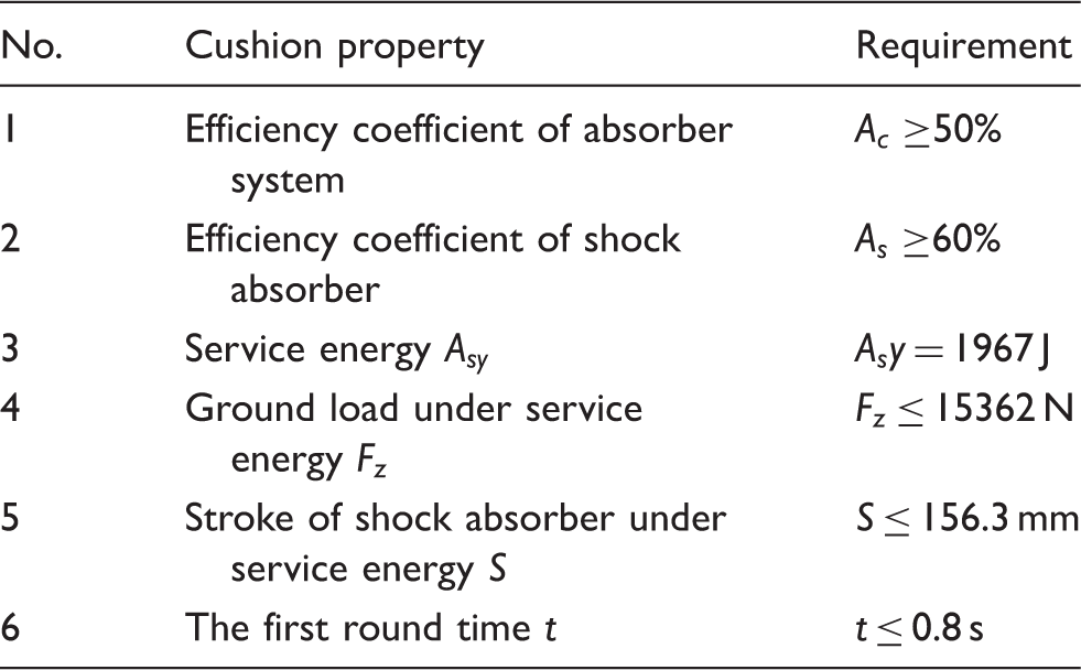
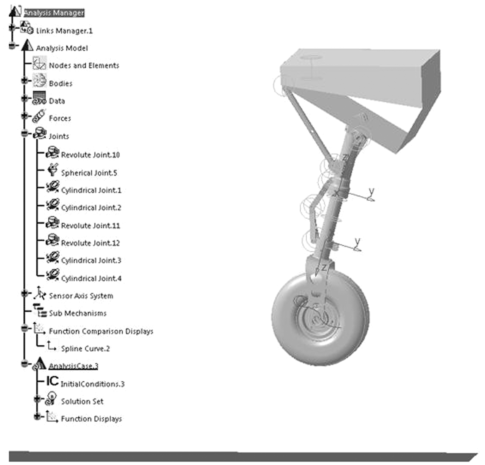
Absorbing energy curve of test under initial parameters. Drop test results based on initial parameters Requirements of cushion properties The nose landing gear is a type of pillar, consisting of rotating shaft, pillar, twisting force arm, and wheel-fork, wheel and so on, among which the pillar is the shock absorber. According to the CATIA 3D digital model, there are some steps to establish a virtual prototyping model in least mean square (LMS) Virtual. Lab Motion, such as model simplicity, definition of motion pair, definition pavement, definition of elastic parameters of tire and shock absorber above, initial conditions and so on. So the final simulation model of landing gear is shown in Figure 3.
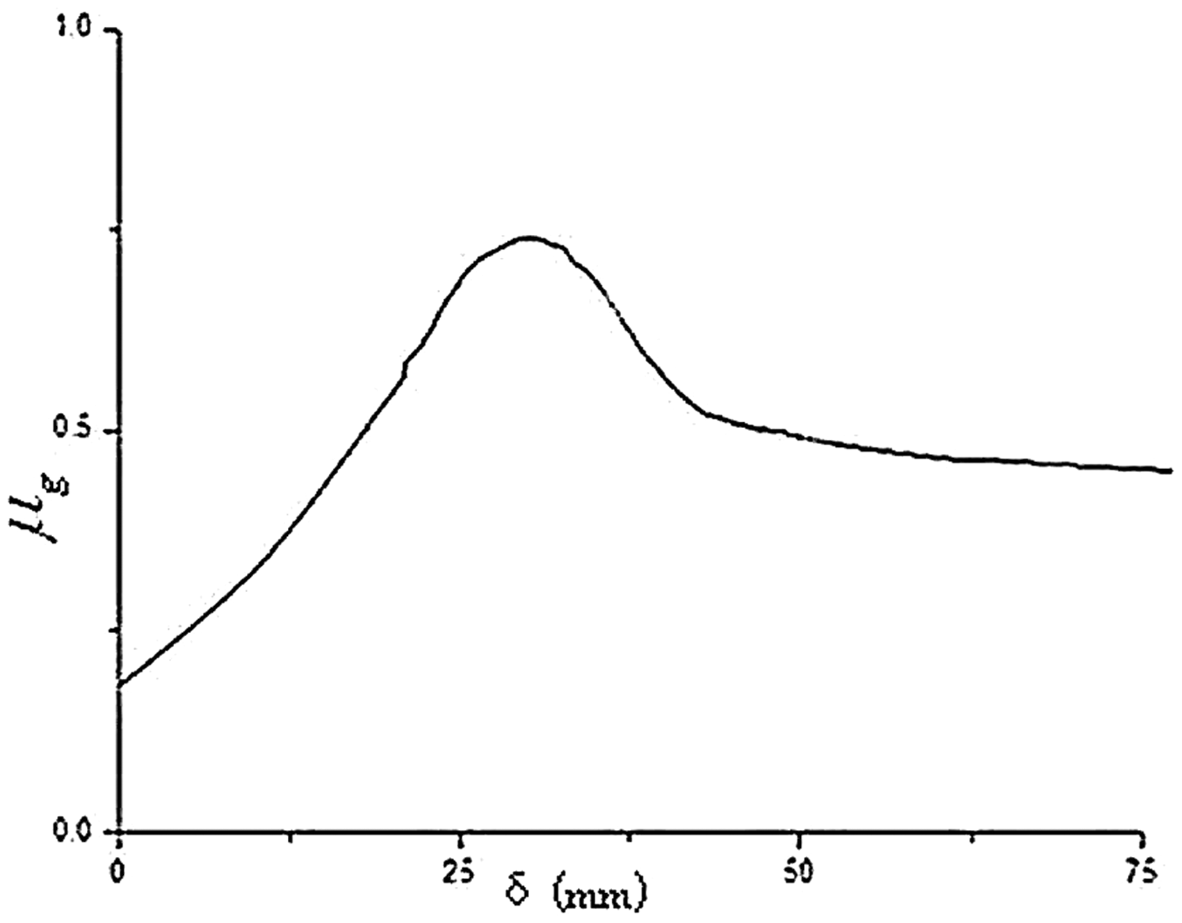
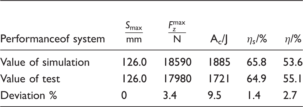
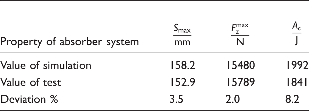
Simulation model of landing gear. Because setting a different friction coefficient in simulation produces different cushion properties, soothe input of the curve of The curve of Simulation results in comparison with test data under initial parameters Look for the optimal parameter configuration to reach the requirements of cushion properties. In fact, in the process of optimization make the parameters of the shock absorber as design variables, and the specific optimization model can be described as follows:
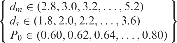
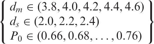
Objective function: absorbing energy of shock absorbing system Ac. Design variables: the diameter of main oil hole dm, the diameter of one-way oil hole ds (considering the diameter of four oil holes equal), initial pressure of shock absorber Po. Combined diameter of oil hole with the actual minimum adjusting limit of the initial pressure, specify dm, ds, Vo as discrete variable, 0.2 mm and 0.2 Mpa as discrete scales respectively. Constraint function: the maximum stroke of shock absorber According to the experimental results under the initial parameters, ascertain that increasing the diameter of oil holes and initial pressure of the shock absorber, to make the constraint function within the scope of constraint. Based on practical experiences, define the variation ranges of design variables, as followed in equation (6).
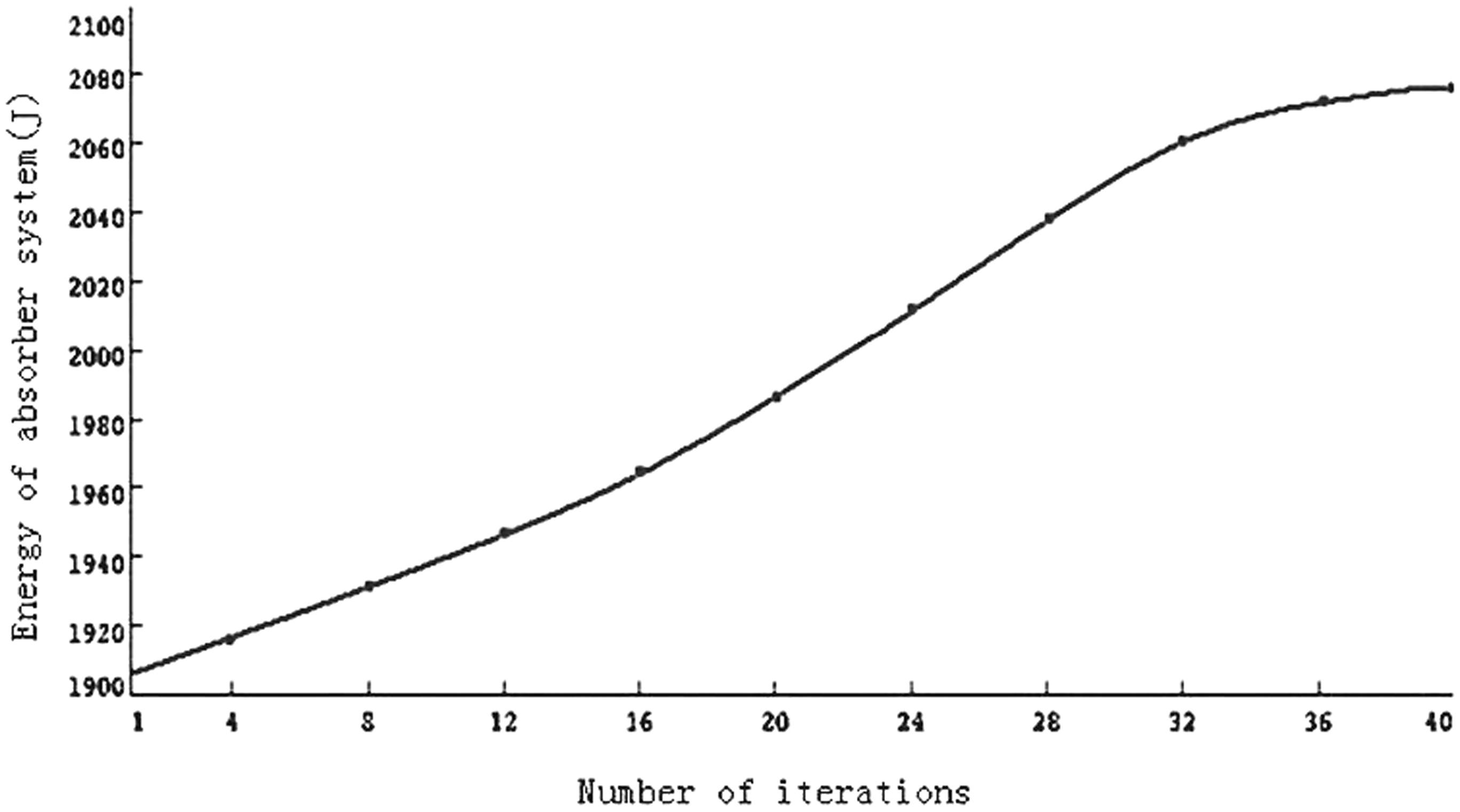
Set design variables and response function in simulation mode, and add the validated ranges of design variables in equation (6), and then exert variation range on the constraint function and make the objective function as max Ac. So the simulation model for optimization can be established with the specific parameter settings, as shown in Figure 3 above. Carry out optimizing by running LMS software, so the iterative curve of objective function can be obtained, described in Figure 5. And then some specific values of objective function and design variables can be extracted from the iterative curve, listed in Table 5.
The iterative procedure.
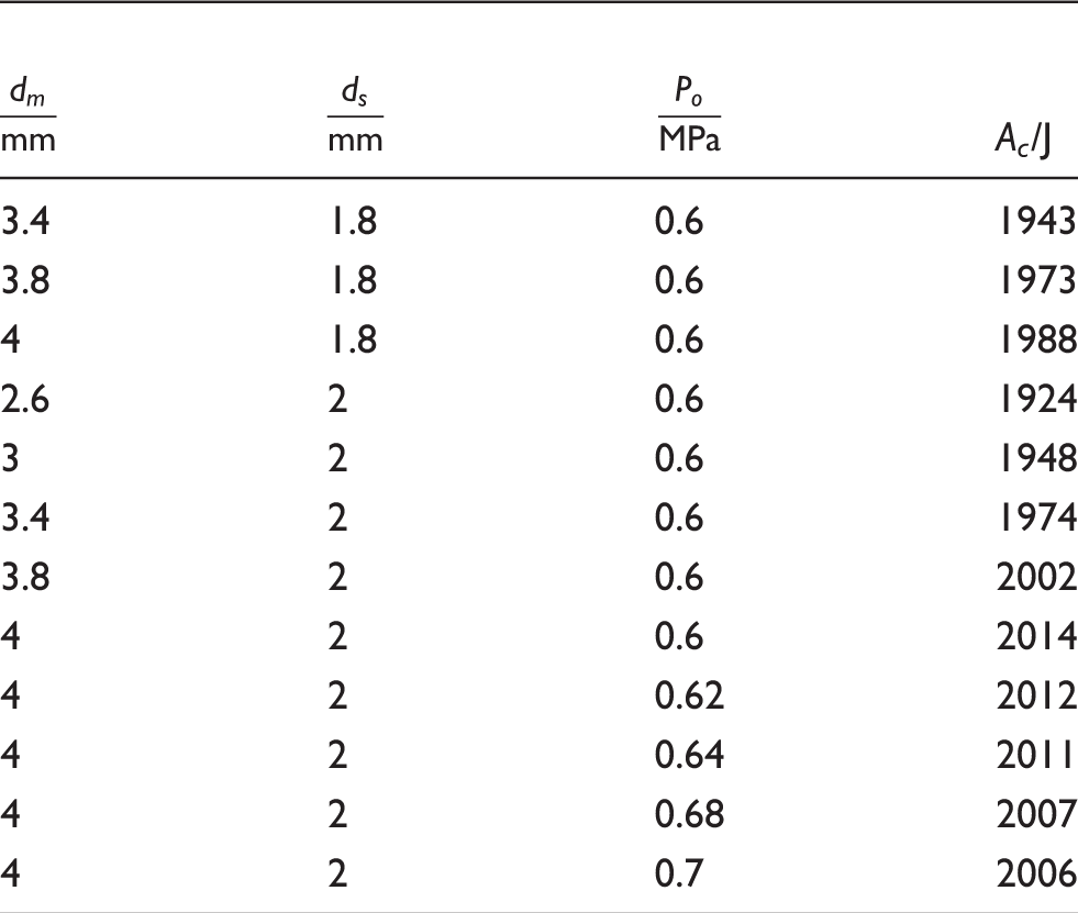
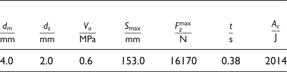
Ac in response to kinds of parameters First optimization results of cushion properties According to the values of parameters in Table 6, alter diameters of the main oil holes and the one-way oil holes. The specific steps are as followed: (a) drill the stigmas of the oil holes referring to the diameters above; (b) replace the stigmas in oil hole flange of the shock absorber; (c) complete the assembling of landing gear, and then fill nitrogen gas to make the initial pressure 0.6 MPa. Other parameters like wheel turning speed, casting height, valid cast-weight and so on keep the same as those of Table 1, and then carry out the drop test. The results are the absorbing energy of the shock absorber and absorber system as shown in Figure 6, and some main property parameters as listed in Table 7.
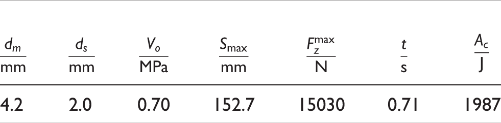
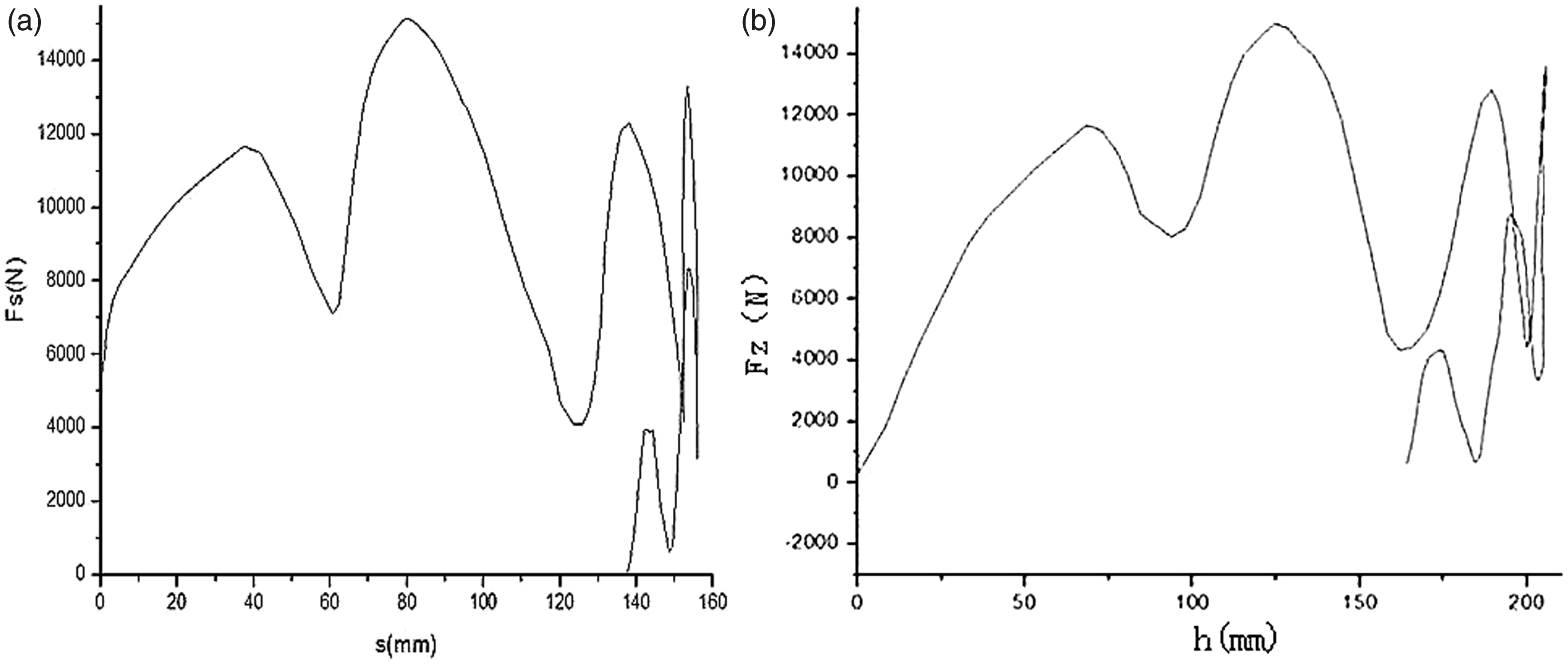
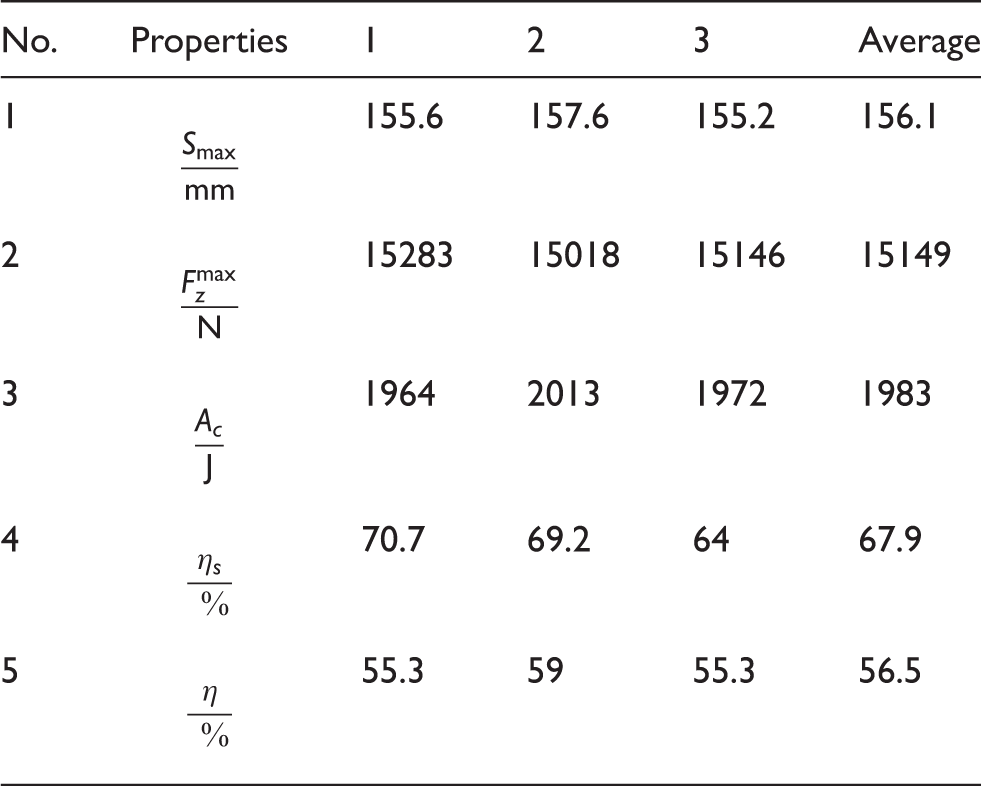
Absorbing energy curve of drop test under 4 mm oil holes. The results of drop test under 4 mm main oil hole Compared to the curve of the initial test, its fuller curve indicates that the cushion property has been improved from before. Specifically speaking, the maximum stroke of the shock absorber has been increased; the maximum vertical load has been deduced; the absorbing energy of the absorber system has been greater. However, in comparison to the requirements of design, the maximum vertical load is a little bigger; the absorbing energy of the absorber system slightly trends to the small side. Therefore, it needs adjusting to certain extent, including the enlargements to oil holes and initial pressure of the shock absorber. Simulation results for further optimization in comparison with drop test The final optimization results of cushion properties Based on the final optimization results, triple drop tests are carried out under the conditions where the cast height is increased to 427 mm, the diameter of main oil hole altered to 4.2 mm, the initial pressure of airspace kept as 0.7 MPa and other parameters unchanged. Take the absorbing energy curves of the second test, as shown in Figure 7, to compare with that of Figure 6. It turns out the two curves look similarly, having the same four peaks and the near compression strokes where these peaks occur. On the other hand, the absorbing energy curve is fuller under the optimal parameters, thereby testifying the cushion property boosted.
Absorbing energy curve of drop test under optimal parameters. Experimental results under optimized parameters In order to improve the cushion properties of certain amphibious aircraft landing gear, the paper presents the method of an adjusting-parameter test to establish an accurate simulation model based on LMS. By research, not only it obtains the optimal parameters of simulation model through optimization, but also verifies the reliability of the landing gear with the optimal parameters through a drop test. The optimization results of properties are summarized as: the maximum stroke increases from 126 mm to 156.1 mm; the maximum vertical load decreases from 17980 N to 15149 N; the absorbing energy improves from 1521 J to 1983 J; efficiency coefficients of the absorber system and shock absorber are both boosted. The improved cushion properties of the landing gear better meet the airworthiness standard technology index compared to that of the initial test. Therefore, this study proves the effectiveness of the proposed approach and it can be applied to amphibious aircraft for improving cushion properties of landing gear. This work was supported by the Fundamental Research Funds for the Central Universities, (grant number NS2012081) and the Foundation of Graduate Innovation Center in Nanjing University of Aeronautics & Astronautics, (grant number KFJJ20110201).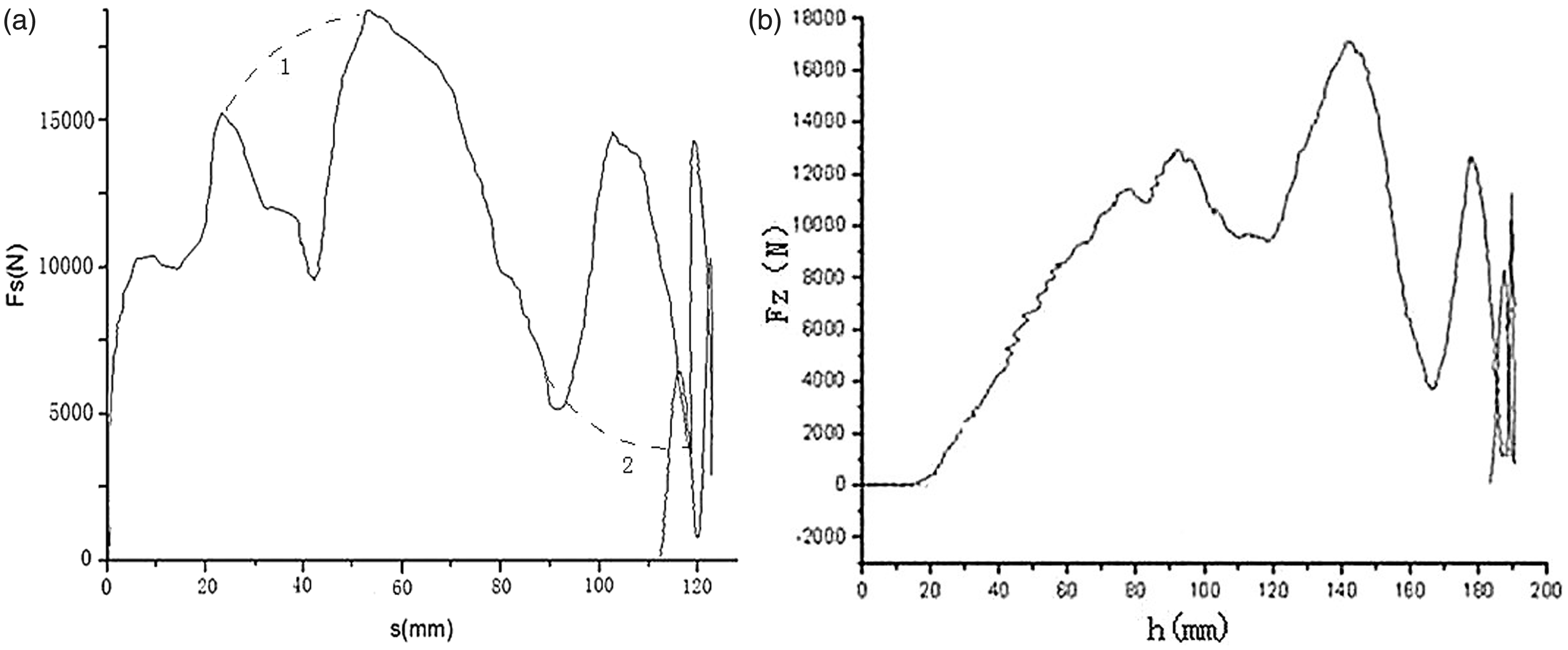
3. Dynamic simulations on drop
3.1. Establishment of simulation model
3.2. Simulation results compared with test data
4. Parameter-adjusting technology for drop
4.1. Optimization procedures of parameter-adjusting
4.1.1. Optimization model
4.1.2. Optimization analysis for the cushion properties
4.1.3. Test under the optimized parameters
4.1.4. Further optimization for parameters considered friction between rolling wheel and rollaway nest
4.2. Drop test under optimal parameters
5. Conclusion
Footnotes
Funding
References


