
Abstract
The development of a control system for the suppression of aeroelastic vibration of a two-dimensional nonlinear wing-flap system based on the ℒ1 adaptive control theory is the subject of this paper. The prototypical aeroelastic wing section model considered here includes structural nonlinearity, parameter uncertainties and gust loads. For the purpose of control, a single trailing-edge control surface is used. The uncontrolled aeroelastic model exhibits limit cycle oscillations beyond a critical free-stream velocity. An ℒ1 adaptive law is developed for the suppression of aeroelastic oscillations using the pitch angle and pitch rate feedback. The control system includes a state predictor. The adaptation gain and the parameter of a filter are properly chosen to satisfy desirable performance bounds on the system trajectories. Simulation results are presented which show that the control system suppresses the oscillatory responses of the system in the presence of large parameter uncertainties and triangular, sinusoidal, and exponential gust loads.
1. Introduction
The new generation of highly flexible and combat aircraft with long slender wings are prone to undesirable aeroelastic instabilities. Aeroelastic phenomena such as flutter and limit cycle oscillations (LCOs) impose constraints on the flight vehicle performance. As such the analysis of aeroelastic dynamics and the design of active control systems for avoiding instability in aeroelastic systems continues to be an active research area (Mukhopadhyay, 2003; Dowell, 2004). Mukhopadhyay (2003) has provided a historical perspective on analysis and control of aeroelastic systems and a large number of references. The stability analysis using the μ method for uncertain aeroelastic models has been attempted (Lind and Brenner, 1999). Aeroelastic behavior of aircraft with freeplay nonlinearity has been considered (Wang et al., 2011a). For the benchmark active control technology (BACT) wind-tunnel model constructed at the NASA Langley Research Center, controllers for flutter suppression have been designed (Waszak, 2001). Researchers have designed flutter control systems using the classical, minmax, pacification methods (Mukhopadhyay, 2000) and the gain scheduling technique (Barker and Balas, 2000). A passivity-based robust controller for the BACT model has been designed (Kelkar and Joshi, 2000). A controller including a neural network has been proposed (Scott and Pado, 2000).
At the Texas A&M University, a two-degree-of-freedom plunging and pitching experimental apparatus has been constructed for examining the aeroelastic behavior and the performance of control systems (Ko et al., 1997). The apparatus includes a nonlinear spring along the pitch axis and it exhibits limit cycle oscillations beyond a critical speed (Sheta et al., 2002). For this model, linear and feedback linearizing control systems have been designed (Block and Strganac, 1998). A variety of adaptive control laws for suppressing oscillations have been developed (Ko et al., 1999; Xing and Singh, 2000; Bhoir and Singh, 2004; Platanitis and Strganac, 2004; Behal et al., 2006; Reddy et al., 2007). Based on the immersion and invariance principle, adaptive laws for the aeroelastic model have been also proposed (Lee and Singh, 2009, 2010). Marzocca et al. (2001) have examined the aeroelastic responses of a plunging–pitching model to gust and blast pressure signatures. Recently, Wang et al. (2011b) have designed an adaptive control law using leading- and trailing-edge flaps, and demonstrated effectiveness of the controller in attenuating the effect of gust loads given by Marzocca et al. (2001).
Recently, a new ℒ1 adaptive control theory has been developed for the control of uncertain nonautonomous nonlinear systems (Cao and Hovakimyan, 2008; Hovakimyan and Cao, 2010). This design uses a state predictor similar to indirect adaptive systems; however, the control input is obtained by filtering the estimated control signal. This low-pass filter allows the low-frequency control signal to pass. The use of the filter for generating the actuating control signal provides several advantages over the traditional adaptive systems. The ℒ1 adaptive controller can achieve fast parameter adaptation and yields quantifiable performance bounds. This design approach has been applied for the wing-rock control (Cao and Hovakimyan, 2006), missile control (Cao and Hovakimyan, 2009), and the other aerospace vehicles. Gregory et al. (2007) have considered the control of a flexible wing using four control surfaces. This control system includes an ℒ1 adaptive controller wrapped around a nominal controller with a proportional and integral feedback structure. (Readers may refer to Hovakimyan and Cao (2010) for additional references.) Several control systems for the prototypical wing section of Block and Strganac (1998) have been designed in the past, but the application of ℒ1 adaptive theory for this model has not been attempted. As such, it is of interest to develop an ℒ1 adaptive flutter controller for the prototypical plunge–pitch 2-D aeroelastic system in the presence of gust loads.
In this paper, the design of a control system for the control of an aeroelastic system, in the presence of parameter uncertainties and gust loads, is considered. The design is based on the ℒ1 adaptive control theory (Hovakimyan and Cao, 2010). This aeroelastic model has two degrees of freedom and governs the nonlinear plunge and pitch motion of the wing section (Ko et al., 1997). This type of model has been traditionally used for the theoretical as well as experimental analysis of two-dimensional (plunge and pitch) aeroelastic behavior. The model has pitch polynomial type structural nonlinearities and uses a single control surface for the purpose of control. It is assumed that all of the system parameters, except the sign of a single control input coefficient, are not known. The aeroelastic model has quasi-steady linear aerodynamic aerodynamics; however, it is noted that one can extend this approach to the case of nonlinear aerodynamics as well. This aeroelastic model exhibits limit cycle oscillations when the free-stream velocity exceeds a critical value. An ℒ1 adaptive control system for the pitch angle trajectory control is derived. The control law is synthesized by feeding the pitch angle and its derivative. The control system includes a state predictor for the derivation of the update law. In the closed-loop system, the pitch angle and plunge displacement trajectories are stabilized. Unlike the traditional adaptive systems, the designed system has good robustness properties, and can achieve quantifiable performance bounds on the system trajectories and the control input by the choice of adaptation and feedback gains. Simulation results for the control of the oscillatory responses of the aeroelastic system are obtained. It is seen that the controller suppresses the oscillatory motion of the system, despite large parameter uncertainties and triangular, exponential and sinusoidal gust loads.
The organization of the paper is as follows. Section 2 presents the aeroelastic model. A control law including a state predictor is designed in Section 3. Finally, Section 4 presents the simulation results.
2. Aeroelastic model and control problem
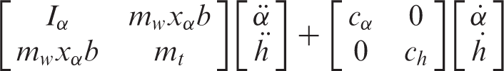
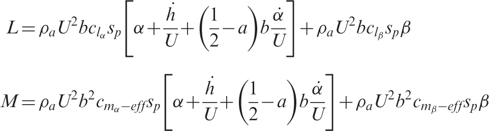
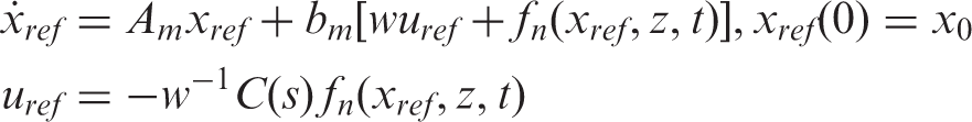
Figure 1 shows the aeroelastic model. A laboratory model of this has been developed at the Texas A&M University for performing experiments. The model has two degrees of freedom. The differential equations describing the pitch angle (α) and the plunge displacement h of the wing including the gust load are governed by second-order differential equations (Ko et al., 1997; Platanitis and Strganac, 2004; Wang et al., 2011b). These are
Aeroelastic model.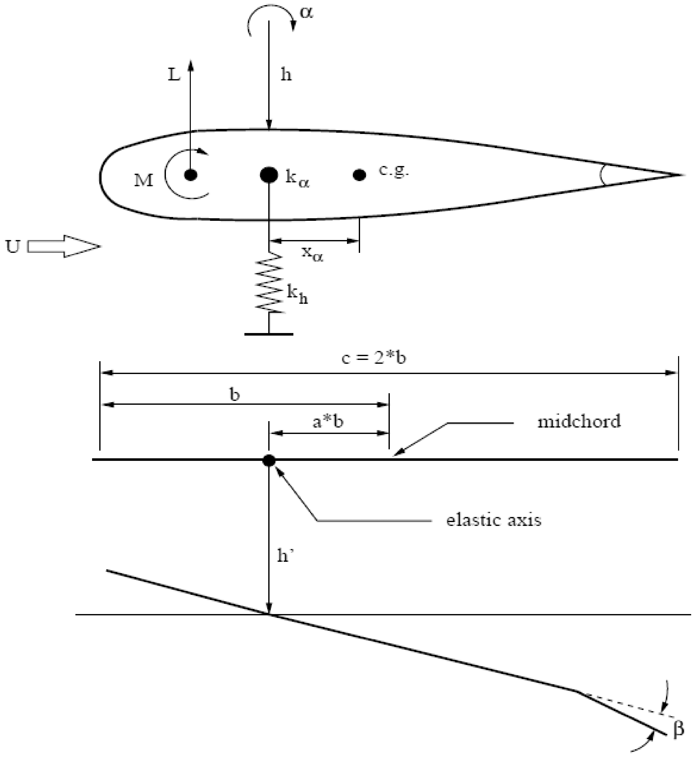
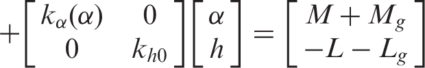
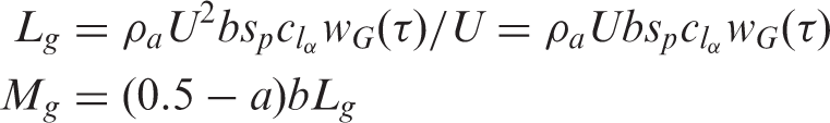
The aerodynamic force and moment due to the wind gust is modelled as (Marzocca et al., 2001)
The nonlinear function kα(α) has a polynomial form of second degree and is given by

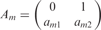
Define the matrix


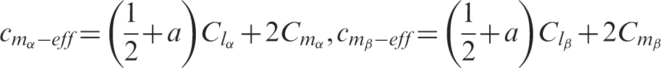
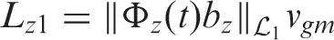
Let α be the controlled output variable. We are interested in the design of an ℒ1 adaptive control system for the stabilization of the pitch angle and plunge displacement trajectories using α and
3. ℒ1 adaptive law
In this section, an adaptive control system is designed for the suppression of the plunge and pitch oscillatory motion of the aeroelastic model using the trailing-edge control surface. The design of the control system is based on the ℒ1 adaptive control theory (Hovakimyan and Cao, 2010). Here the derivation of the controller for the aeroelastic model is briefly presented. (The proof of stability can be completed by following the steps given of Hovakimyan and Cao (2010).)
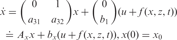
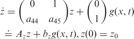
First of all, for the derivation of the control system, a state transformation is introduced. Define new variables


Then the equations of motion can be expressed in a compact form as
Assumption 1:
The parameters a ik and the nonlinear functions f(x, z, t) and g(x, t) are not known.
Let b
m
be a nominal value of the uncertain parameter b1. Define b1 = b1mw, where b1m is a known nominal value and w is an unknown parameter satisfying

Consider a Hurwitz matrix given by

Assumption 2:
There exists B > 0 such that f n (0, t) ≤ B for all t > 0.
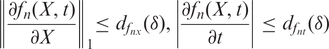
Assumption 3:
For ‖X‖∞ ≤ δ, where δ > 0 is an arbitrary number, the partial derivatives of f
n
(X, t) are bounded as
Assumption 4:
The flow velocity and the parameter a are such that A z is Hurwitz.
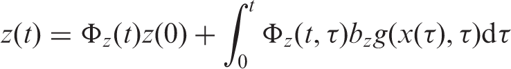
In view of Assumption 4, for bounded x(t) and d
gi
(t), the trajectory z(t) of equation (9) is bounded; that is, the z-dynamics are bounded input bounded state stable with respect to z0, x, and dg3. Let


The matrix A
m
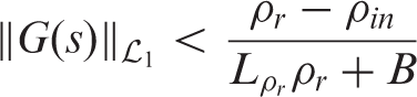
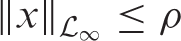
has stable eigenvalues. As such there exists a ρ
in
> 0 such that ‖x
in
‖ℒ∞ ≤ ρ
in
, where x
in
(s) = (sI − A
m
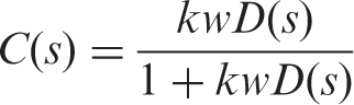
)−1x0. For the design of the controller, consider a strictly proper transfer function D(s) such that

Let


Then for cancelling unknown terms in the derivative of V along the solution of equation (22), the adaptation law is chosen as
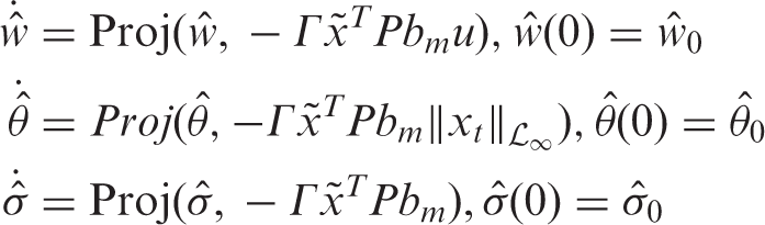
In view of equation (25), one finds that the adaptation law is a function of
The estimated parameters are used to compute the control law of the form

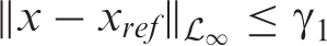
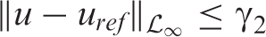
For the evaluation of performance bounds, consider a reference system given by

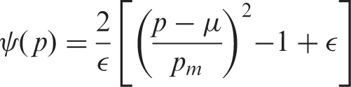
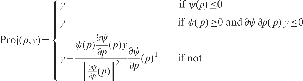
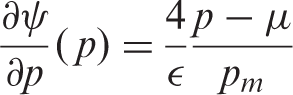
Here for synthesis, a smooth projection algorithm is used for each parameter

4. Simulation results
In this section, numerical results for the model given by (Platanitis and Strganac, 2004) are obtained. The system parameters are given in the appendix. The chosen initial conditions h(0) = 0 (m), α(0) = 5.729°,
The poles of the linearized system for U = 8 m/s and a = −0.6719 are (−0.5065 ± 10.2038i, −0.8934 ± 14.5665i), and the zeros of the transfer function relating α and u are −1.6403 ± 16.8671i. The poles of the linearized system for U = 13.28 m/s and a = −0.6719 are (1.3071 ± 12.9398i, −2.8512 ± 12.4120i), and the zeros of the transfer function relating α and u are −1.8089 ± 16.8499i. Thus the open-loop system is stable for U = 8 m/s, and unstable for U = 13.28 m/s, but the linearized system has minimum phase transfer function relating α and u for these free-stream velocities.
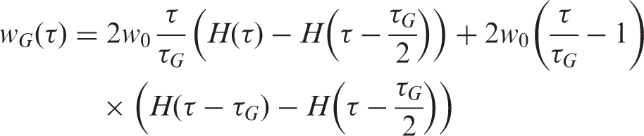
The velocity distributions of gust given by Marzocca et al. (2001) and Wang et al. (2011b) are used for simulation. The selected velocity distributions (w
G
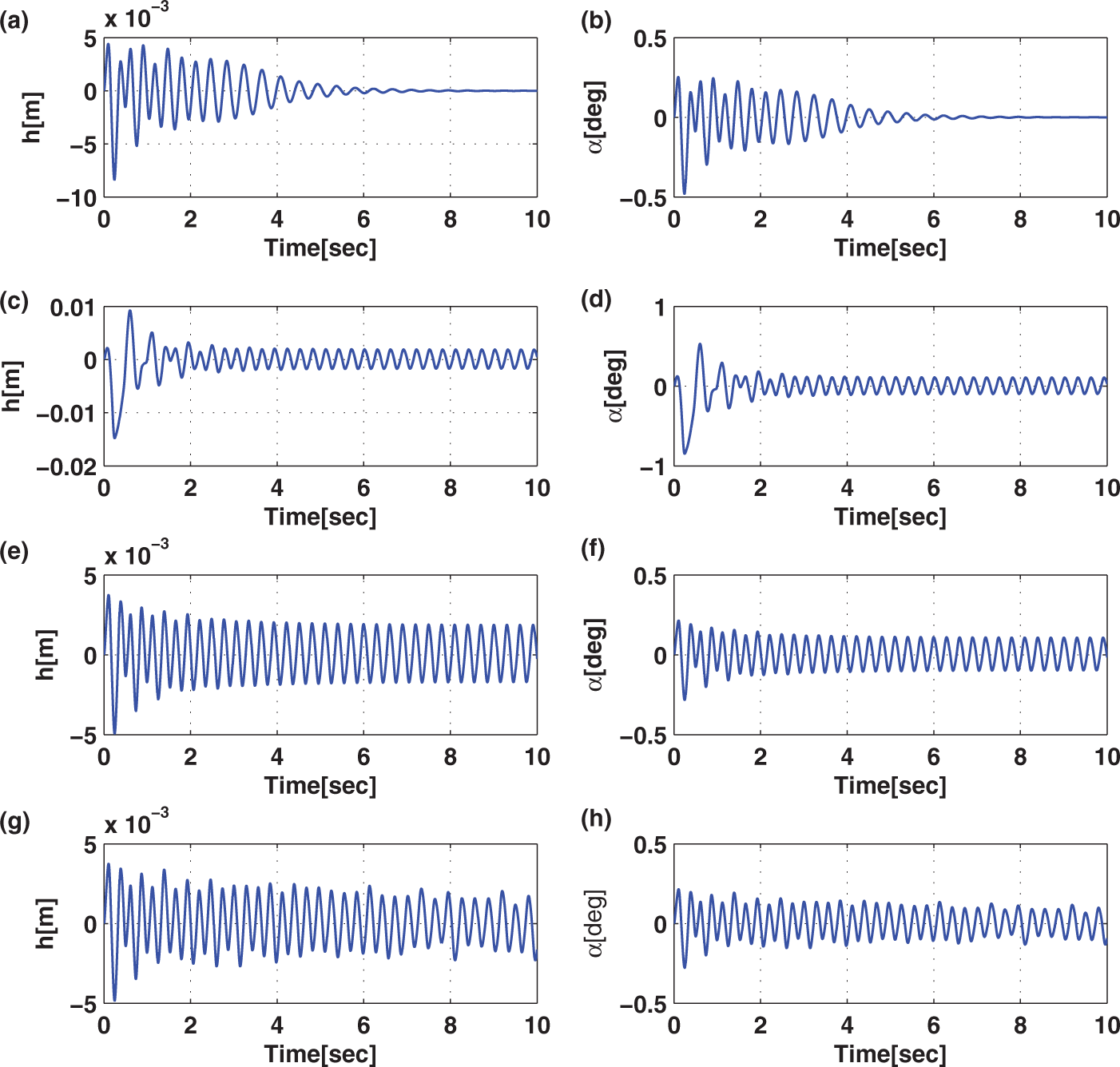
(τ) ) for (a) triangular gust, (b) exponential (graded) gust, (c) sinusoidal gust, and (d) sum of sinusoidal and persistent random gust are shown in Figure 2. The triangular and sinusoidal gusts have finite duration. The responses of the open-loop system (u = 0) for the velocity distributions of Figure 2 are plotted in Figure 3. For triangular w
G
(τ), the pitch angle and plunge displacement converge to zero for U = 8 m/s (Figure 3(a) and (b)). However, for U = 13.28 m/s, the system exhibits LCOs after initial transience in all cases (Figure 3(c)–(f)), except for the random velocity distribution. For the random w
G
, the oscillatory motion is nonperiodic (Figure 3(g) and (h)).
External disturbances: (a) triangular gust; (b) exponential (graded) gust; (c) sinusoidal gust; (d) sinusoidal and persistent random gust. Open-loop LCO in the open-loop system: (a), (b) h (m) and α (°) under triangular gust for w0 = 0.5, U = 8 (m/s); (c), (d) h (m) and α (°) under graded gust for w0 = 0.07, U = 13.28 (m/s); (e), (f) h (m) and α (°) under sinusoidal gust for w0 = 0.07, U = 13.28 (m/s); (g), (h) h (m) and α (°) sinusoidal plus persistent random gust for w0 = 0.07, U = 13.28 (m/s).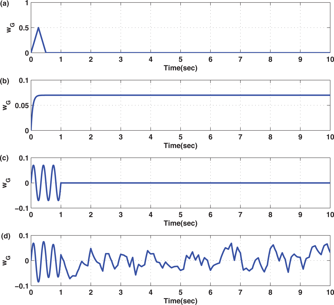
Now the closed-loop responses for the model equation (1) including the control law equation (26), adaptation law equation (25) and gust load are obtained. Closed-loop responses are obtained using triangular gusts with intensity w0 = 0.5 and 2.0. For a realistic simulation, similar to Wang et al. (2011b), control surface deflections are allowed to saturate at 15°.
Case A. Adaptive control: triangular gust, U = 8 m/s
For examining the performance of the controller, the closed-loop system including the triangular gust for U = 8 m/s and a = −0.6719 is simulated. The velocity distribution shown in Figure 2(a) is
Adaptive control for triangular gust, w0 = 0.5, U = 8 m/s: (a) plunge displacement h (m); (b) pitch angle α (°); (c) control input β (°); (d) estimated signals 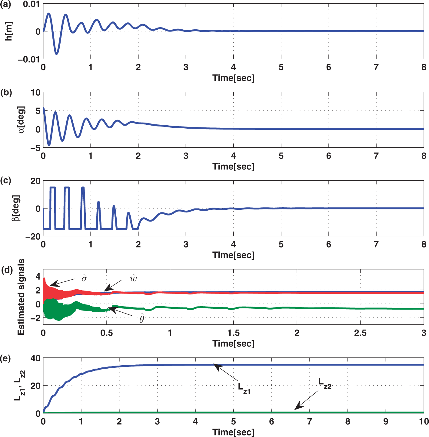
Case B. Adaptive control: triangular gust, U = 13.28 m/s
Now the closed-loop system with triangular gust of larger intensity w0 = 2 and U = 13.28 m/s is simulated. Selected responses are shown in Figure 5. It is observed that in spite of the stronger gust, the pitch angle converges to zero in 2 seconds, but the plunge displacement is regulated to zero in about 2.8 seconds. It is pointed out that the control input gain b1 increases with the free-stream velocity; and, therefore, control effectiveness of the flap improves.
Adaptive control for triangular gust, w0 = 2, U = 13.28 m/s: (a) plunge displacement h (m); (b) pitch angle α (°); (c) control input β (°); (d) estimated signals 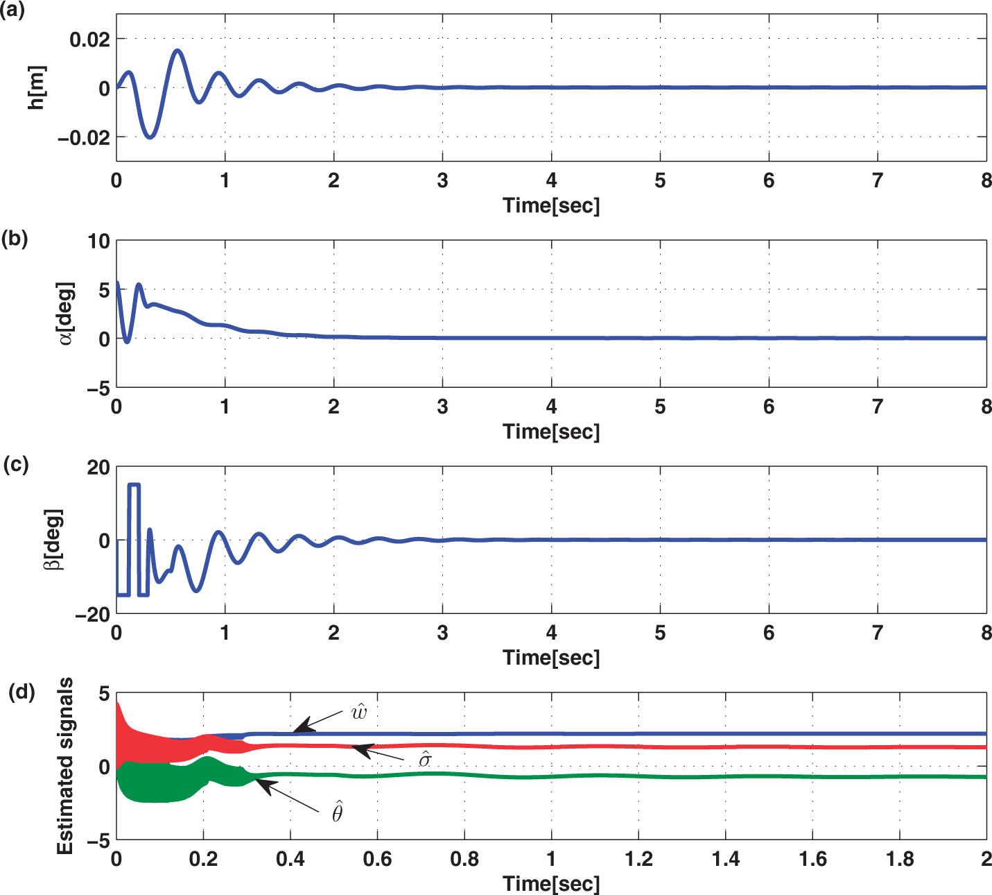
Case C. Adaptive control: sinusoidal gust, U = 13.28 m/s
The simulation is done using the sinusoidal w
G
(τ) of the form
Adaptive control for sinusoidal gust, w0 = 0.07, U = 13.28 m/s: (a) plunge displacement h (m); (b) pitch angle α (°); (c) control input β (°); (d) estimated signals 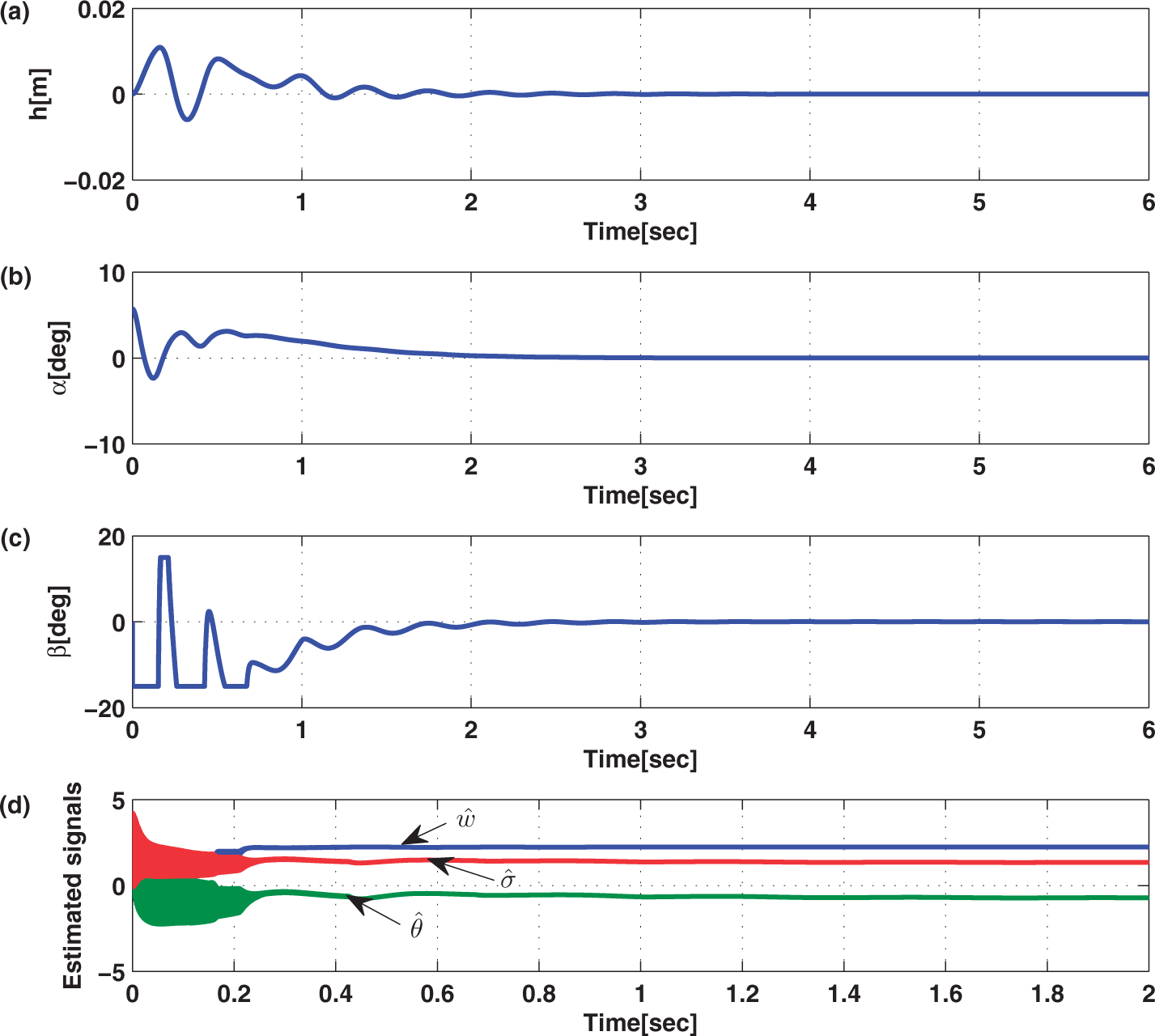

Case D. Adaptive control: exponential gust, U = 13.28 m/s
For simulation, exponential (graded) gust given by
Adaptive control for exponential gust: w0 = 0.07, U = 13.28 m/s: (a) plunge displacement h (m); (b) pitch angle α (°); (c) control input β (°); (d) estimated signals 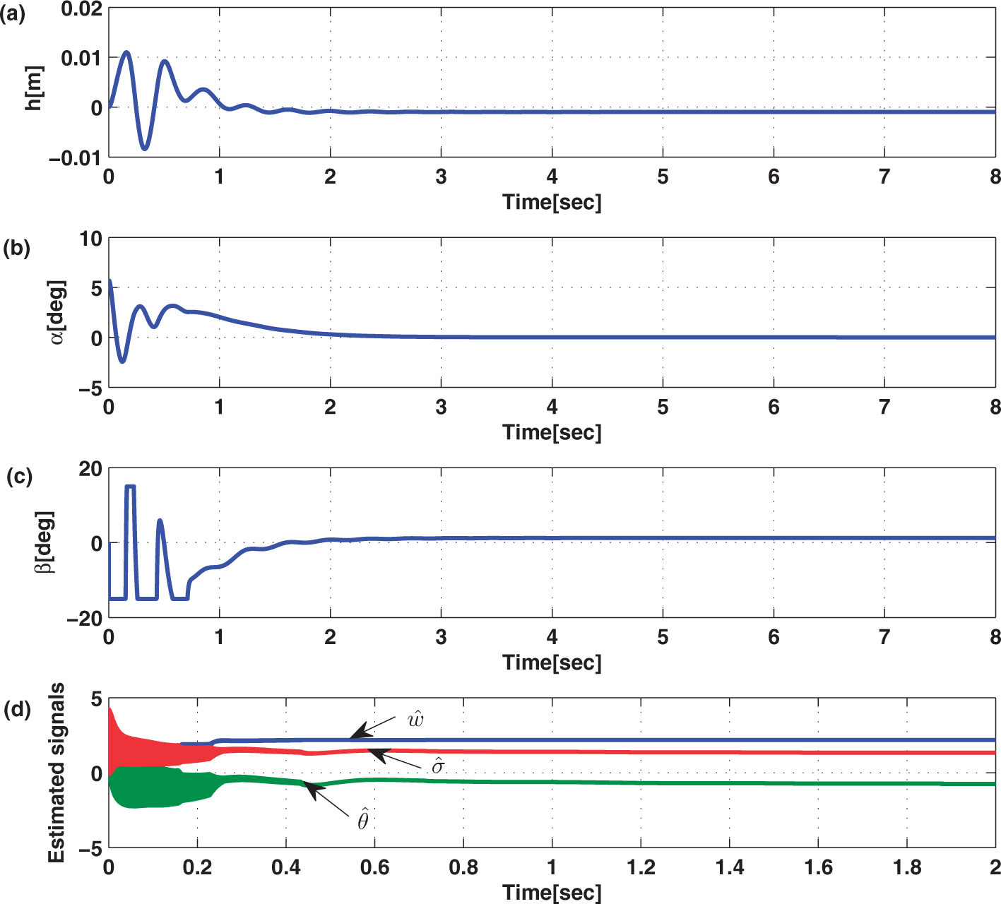
Simulation is also done for the exponential gust of Figure 7, but a larger value of w0 = 1 is assumed. Remaining parameters of Figure 7 are retained. The selected responses are shown in Figure 8. It is seen that the oscillations in α and h are completely suppressed in about 2 seconds. For this case the clamped value of the control input is 18° instead of 15°. The pitch angle converges to zero, but the plunge displacement converges to the equilibrium value of −0.0141 (m) in the steady state.
Adaptive control for exponential gust, w0 = 1.0, U = 13.28 m/s: (a) plunge displacement h (m); (b) pitch angle α (°); (c) control input β (°); (d) estimated signals 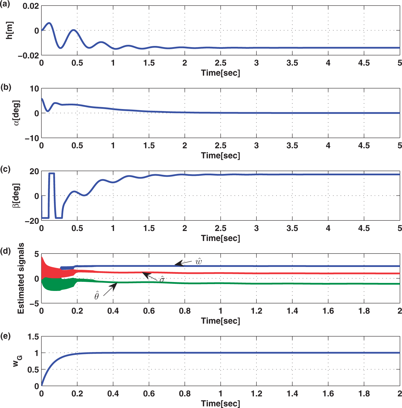
Case E. Adaptive control: combined sinusoidal and persistent random gust, U = 13.28 m/s
Now the effect of the persistent random gust combined with the sinusoidal gust shown in Figure 2(d) is examined. The net velocity
Adaptive control for sinusoidal plus persistent random gust, w0 = 0.07, U = 13.28 m/s: (a) plunge displacement h (m); (b) pitch angle α (°); (c) control input β (°); (d) estimated signals 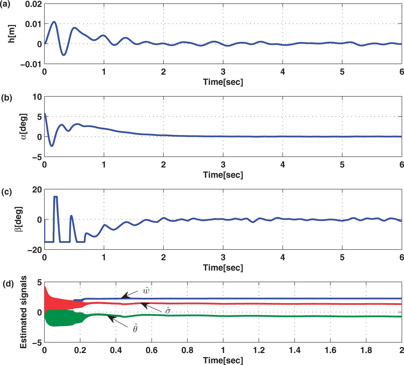

Extensive simulation has been performed for various kinds of wind gust. In each case, it has been observed that the ℒ1 adaptive control law accomplishes control of the oscillatory motion of the aeroelastic system, in spite of the uncertainties in the parameters and wind gusts of different shapes.
Now it is appropriate to compare the ℒ1 adaptive law using a single trailing-edge control surface derived here and the direct adaptive control law designed using trailing- and leading-edge (two) control surfaces by Wang et al. (2011b). In their paper, unknown functions are approximated by multi-layer neural networks. As such a large number of parameters (weights) (82 parameters) are needed for obtaining good approximation of the unknown functions. In this ℒ1 control system, only three parameters are estimated; and, therefore, the adaptation law is simple. Of course, a state predictor of dimension two is needed here. It is pointed out that similar to Wang et al. (2011b), control saturation has been introduced here to limit the flap deflection. It is seen that the convergence characteristics of the closed-loop system of this paper are somewhat similar to those of Wang et al. (2011b). Figure 8 obtained for U = 13.28 (m/s) and exponential w G (τ) with a larger value w0 = 1 shows that the ℒ1 control system suppresses the oscillatory motion in two seconds; but it is about one second for the controller of Wang et al. (2011b). The control saturation level in Figure 8 is 18°, which is slightly larger compared with 15° used by Wang et al. (2011b). Also similar to Wang et al. (2011b), h converges to a nonzero value, but this terminal magnitude (0.0141 (m)) of h is larger than the value 0.008 m of Wang et al. (2011b). Of course, the ℒ1 adaptive law utilizing a single flap cannot suppress the oscillations in h in the presence of persistent (long lasting) sinusoidal gusts. For the model with two control surfaces used by Wang et al. (2011b), zero dynamics do not exist and it is possible to control both α and h responses for all U and a.
5. Conclusions
In this paper, a controller for the control of a nonlinear uncertain two-dimensional aeroelastic system based on the ℒ1 adaptive control theory was developed. The plunge–pitch dynamics of the model included uncertain parameters as well as gust load. A single trailing-edge flap was used for control. The ℒ1 adaptive law was developed for the pitch angle control. The control system included a state predictor and filtered estimated control signal was synthesized using pitch angle and pitch rate feedback. In the closed-loop system, plunge displacement and pitch angle oscillations were suppressed. Unlike the traditional adaptive systems designed for aeroelastic models, the derived controller provides explicit performance bounds on state trajectory and control input. There exists flexibility in the choice of controller parameters. Enhanced performance is possible by choosing large adaptation gain. Simulation results for a variety of gust loads was obtained. It was found that the controller accomplished suppression of the plunge and pitch angle trajectory oscillations, despite uncertainties in the model parameters and triangular, sinusoidal and exponential gust loads. However, in the presence of random gust, tiny fluctuations around zero exist in the plunge response.
Nomenclature
System matrices Nondimensionalized distance from the midchord to the elastic axis Semichord of the wing Plunge and pitch structural damping coefficient Transfer functions Filter parameter Plunge displacement Moment of inertia of the wing about the elastic axis Aerodynamic and disturbance moments and lift Plunge and pitch structural spring constant Mass of the plunge–pitch system Mass of the wing Span Free-stream velocity, flap deflection Unknown parameters Parameter estimates Disturbance velocity State vectors Nondimensionalized distance measured from the elastic axis to the center of mass Density of air Pitch angle, adaptation gain
Footnotes
Funding
This research received no specific grant from any funding agency in the public, commercial, or not-for-profit sectors.