






Abstract
This paper presents two soft computing techniques, fuzzy logic and neural network, to design a new control scheme for switching a shunt active power filter (APF). This control scheme consists of three control loops, namely a voltage loop, current loop and reference generator. The reference current signal generated by this controller is used to generate gating pulses for APF switches. The reference generator is based on neural network or fuzzy logic. The performance of the proposed neural controller is evaluated and compared with a linear control scheme, incorporating a resonant selective linear reference generator. Simulations are carried out using Matlab Simulink and the results show that the proposed system is capable of compensating the harmonic current to a minimum level.
1. Introduction
The intensive use of power converters and other nonlinear loads has increased the deterioration of power system voltages and current waveforms. Thus the current wave form can become quite complex depending upon the type of load and its interaction with other components in the system. One of the major effects of power system harmonics is to increase the current in the system. It also causes other problems like greater power losses in distribution and failure of protection devices. Due to these problems the quality of electrical power is an object of great concern. A power line conditioner like an active power filter (APF) can be used to minimize the harmonic distortion current (Wu and Jou, 1996; El-Habrouk et al., 2000; Green and Marks, 2005). The main purpose of a shunt APF is to compensate the harmonic current created by the system. Various control methods of APF systems have been used.
The linear control strategy consists of two control loops and a reference generator. The reference signal is generated by an indirect method (Kumar and Mahajan, 2009). That is by means of sensing the grid voltage. A resonant selective harmonic compensator is used for generating reference signal. It consists of several generalized integrators like a second order band pass filter with high gain and low band width. Thus it will not affect the dynamics of the control loop. Attenuation of a specific harmonic current is attained by these integrators. Band pass filters are tuned to resonate at an odd multiple of grid frequency. The main advantages of this method are good dynamic and transient performance. By this approach most harmful harmonics from load current can be eliminated (Yao et al., 2012). This control strategy can be successfully applied to both single phase and three phase APF.
In order to improve the performance of the above control strategy, a soft computing technique can be used. This control strategy is adopted to determine the compensation current. It provides an alternative modeling approach for power system applications. In this paper, the design of a shunt APF based on fuzzy logic and neural network are presented. It is a more efficient approach than the classical methods. Soft computing has experienced an explosive growth in the last decade partially due to uncertainties and vagueness in the process signal and occurrence of random events, and partially due to the nonlinearity and complexity of the processes. Traditionally, the design of a control system is dependent on the explicit description of its mathematical model and parameters. The system can be complex with nonlinearity and parameter variation problems. An intelligent or self-organizing control system can identify the model, if necessary, and give the predicted performance even with a wide range of parameter variation. Soft computing is an alternative solution to meet the process and user’s requirements simultaneously. This paper therefore presents algorithms based on fuzzy logic and neural network for controlling the switching of an APF configuration. The proposed control scheme consists of three control blocks, namely voltage control, current control and a reference generator based on soft computing techniques. The reference current signal generated by this reference generator contains the harmonic components that will be eliminated. This reference signal is controlled by means of a proportional-integral (PI) controller, which in turn, controls the pulse width modulation (PWM) switching the pattern generator (Cirrincione et al., 2006; Asiminoaei et al., 2008; Bhuvaneswari and Nair, 2008). The output of the PWM generator controls the power switches. The reference generator and the other two control blocks play an important role in the dynamic response of the system. These blocks determine the accuracy and order of the harmonics to be injected. The reference current serves as a basis for the creation and injection of a compensation current accomplished by the active filter (Grady et al., 1990). The reference current can be determined using the distorted source current of the system (Singh et al., 1999; Jenopaul et al., 2012).
2. Active power filter topology
Active power filters are the best known tool for the current harmonic compensation. Figure 1 shows the schematic diagram of a single phase APF in a closed loop manner. A diode bridge rectifier with a resistor and capacitor connected in parallel act as a nonlinear load. The APF can be controlled in such a way that it offers high quality compensating components against harmonics produced by the load.
Active power filter circuit.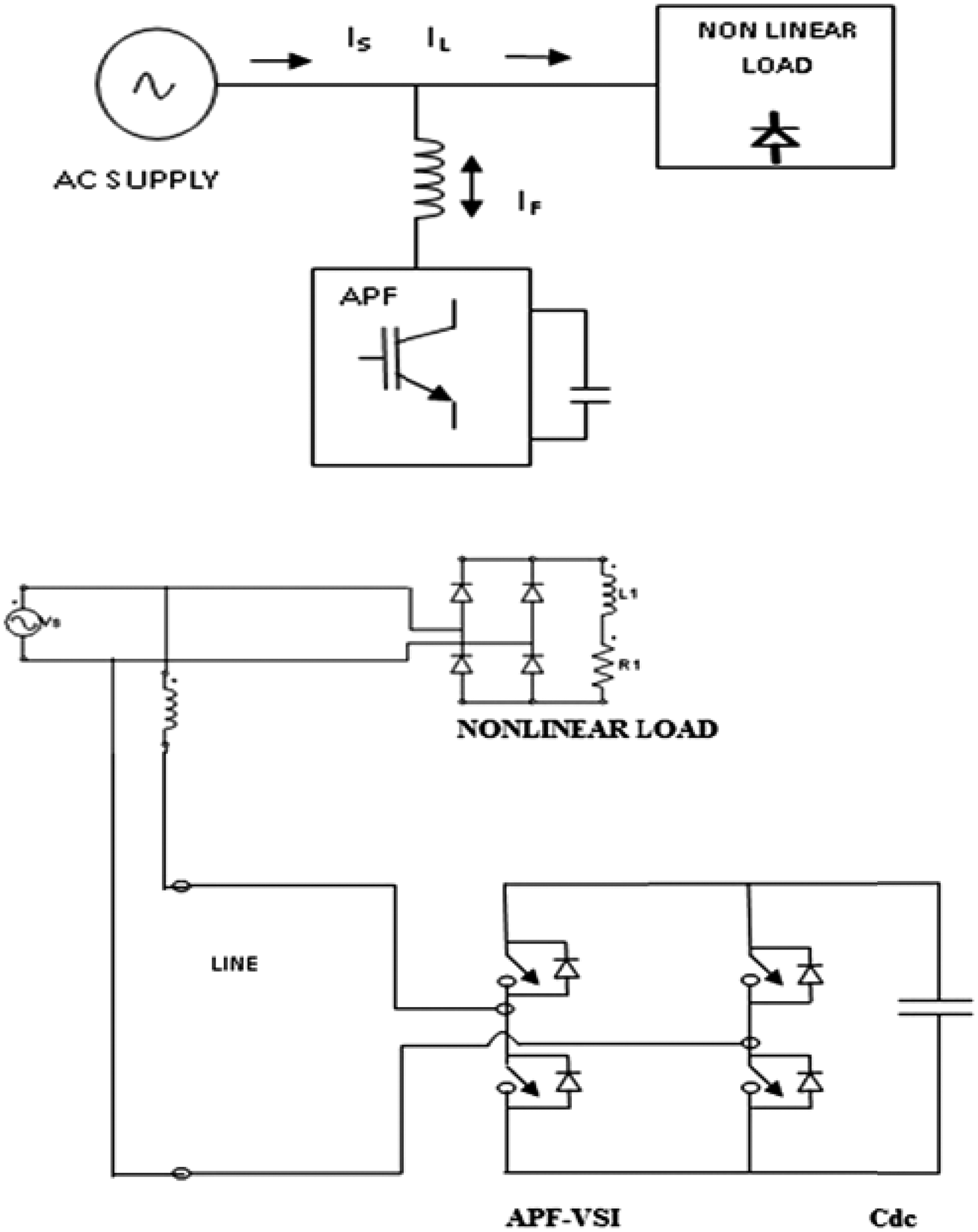
The APF, with its control mechanism shapes the grid current to a sinusoidal form. The compensation principle of shunt active power can be explained as follows. Under normal conditions the supply voltage can be represented as

But when the nonlinear load is connected to the supply, it will draw a non-sinusoidal current. Thus the load current will contain a fundamental component and all other higher order harmonics. It can be represented as

The shunt connected APF will generate a harmonic current iF(t) which compensate the harmonics present in the source current and makes the source current purely sinusoidal in nature.

The compensation current iF is exactly equal to the harmonic content of the load current iL. Hence the APF needs to calculate iF accurately and instantaneously.
3. Control of shunt active power filter
Indirect control method includes an outer voltage control loop inner, inner current control loop. In the indirect control, the reference signal is generated by sensing the grid voltage and grid current is forced to follow this sinusoidal signal. This will reduce the harmonics present in the grid current (Wu and Jou, 1996).The main advantages of this control strategy are that faster dynamic and transient responses. Indirect current control scheme attenuate the current harmonics to a high level, while maintaining the stability. By this method more harmful harmonics can be easily attenuated. The reference current generated by this method contain information regarding most problematic harmonic content that need to be eliminated.
3.1. Direct current (DC) voltage regulation loop
The outer voltage loop is responsible for the DC capacitor voltage regulation. Figure 2 shows the block diagram of outer voltage loop. In the outer voltage loop, the square of the capacitor voltage is compared with the squared reference voltage. The output is regulated with the help of a PI compensator (Corasaniti et al., 2009).
Outer voltage loop.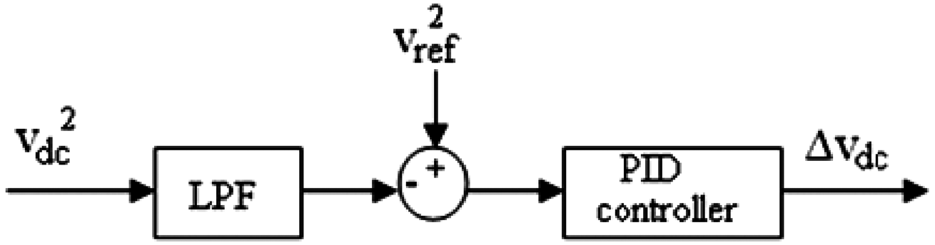
Squared values are used in order to make the design of the loop simpler. In order to reduce the ripple at the output of the PI compensator, an Low Pass Filter (LPF) can be added. The cut-off frequency of the LPF can be made less than twice the grid frequency.
3.2. Current control loop
The inner current control loop will track the reference signal generated by the reference generator. Figure 3 shows the block diagram of the current control loop. Through this current control, the grid current is forced to follow the reference current created. The error signal is controlled using a PI compensator and a control signal is generated. This control signal is used to generate gating pulses to shunt the APF through the PWM technique.
Current control loop.
3.3. Estimation of compensating current
The distortion in the current waveforms deteriorates the performance of the equipment/devices connected in the systems. The analysis of the harmonics is essential to determine the performance and design of this equipment and the optimal location of the harmonic mitigation devices. The total harmonic distortion is used as a harmonic index to identify the effects of different nonlinear loads.
This following sections deal with the reference current generating schemes, including the linear resonant selective harmonic compensator, neural harmonic estimator, and fuzzy logic controller. The reference current signal generated by this reference generator is used to generate gating pulses for the APF switches.
4. Linear reference current generator
The basic approach to generate the reference current consists of multiplying k(t) by the sensed grid voltage Vs.

Using (1), the reference current will follow the shape and phase of the grid voltage. A disadvantage of this basic method is that ref isref replicates the distortion of the grid voltage. To reduce the current-harmonic content, a phase-locked loop (PLL) can be used to generate a low-distorted signal in phase with the grid voltage. The shortcoming of using a PLL can be an increase in the controller computational load. The harmonic content of the grid current comes from two sources: The major one is the inherent distortion from the nonlinear load current, while the other, with probably a minor contribution, is the distortion present in the grid voltage. The basic indirect control reduces the harmonic content considerably but only to a certain level. Forcing the current control to further reduce some remaining load harmonics by means of incrementing the current PI control gains, kpi and kii, can bring the system to instability. On the other hand, the distortion that is potentially contained in the grid voltage will be conveyed to isref and will remain in the generated grid current. In order to overcome the drawbacks described earlier, an improved reference generator, a linear selective harmonic compensator, is proposed in this section (Jaume et al., 2009). It is as shown below.
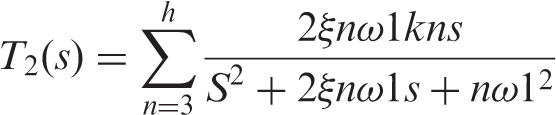
As shown in Figure 4, in the basic approach, a reference signal is generated by multiplying k(t) by the sensed grid voltage Vs, but now this signal is processed in a band pass filter T1(s). It uses a harmonic compensator T2(s). The input of T1(s) is the error current and the input of T2(s) is the grid current is. In addition, the output signals of both filters are now subtracted, and thus, the band pass filters of T2(s) will be in closed-loop operation as notch filters. The subtracted output of two filters is taken as the input reference current for the inner current loop.
Linear reference generator.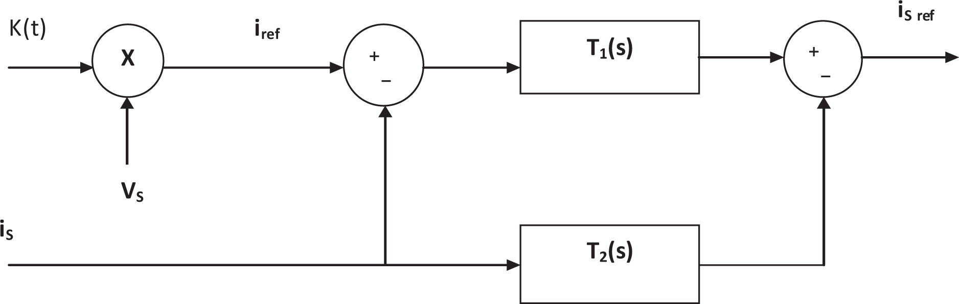
The generalized integrators can be expressed as

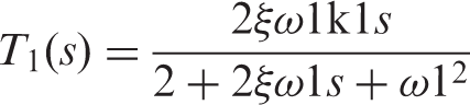
5. Neural harmonic current estimator
The linear reference generator scheme is replaced by an artificial neural network (ANN) of single layer perceptron to control the APF. The ANN is trained offline, using a set of training data generated by Fourier analysis of the source current (El-Habrouk and Darwish 2001). In neural networks, there are two main processes involved- training and testing. In the training process, the network is trained with suitable input and output patterns which is called data set, so that the outputs of the neural network approximate the target values for various input training patterns in the training set. In the testing process, the performance of the network is verified by using the data outside the training data set (Rukonuzzaman and Nakaoka, 2001). Any signal can be represented in terms of the Fourier series


The coefficients An and Bn in a time period T are given by (11) and (12)


The Fourier series can be expressed as,

In which Cn is the amplitude and


Thus, the Fourier series can be written in sine form as in (16)

A neural network for a harmonic component detection consists of a two-layer network in which the input layer = 49 units, and a single output layer. Before feeding data to ANN, the source current signals are sampled at a uniform rate Δt in a half cycle of voltage source as shown in Figure 5. So time values are discrete, kΔt with k = 0, 1, 2 … . . and then given to the ANN for its training, together with the expected output. The testing phase is next after training. In this period there is the value of weighing vectors and the best output.Using these data the best value of the reference current generated can be discovered.Current regulation is performed using a PI controller Figure 6 shows the block diagram of an APF control scheme based on a neural reference generator. The neural reference generator will perform the task of current harmonic computation and generate the reference current signal (Cirrincione et al., 2008).
Sampling of source current. Block diagram of active power filter control scheme based on neural harmonic estimator.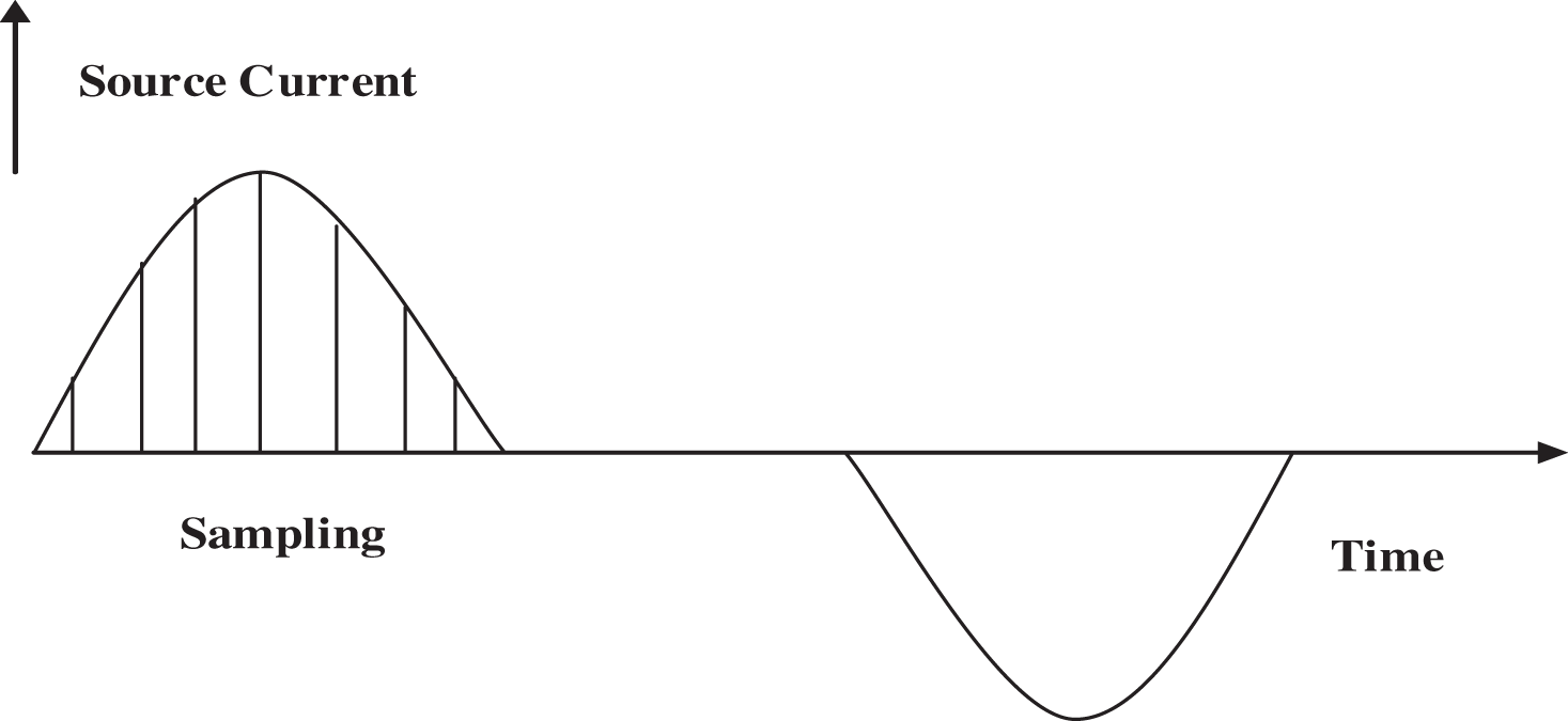
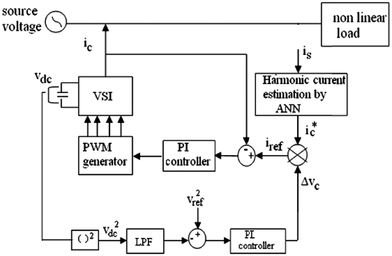
This reference current signal will be sent to the current control block which can be realized using a PI controller. The output of the PI controller is a controlled voltage signal, through which the PWM produces gating pulses for APF inverter control.
6. Fuzzy logic controller
Among the various power filter controllers, one of the most promising is the fuzzy logic controller (Soundarrajan and Sumathi, 2011). A basic fuzzy logic control consists of the following stages: fuzzification, knowledge base, inference mechanisms and defuzzification (Hamzah et al., 2008; Chen, 2011). The knowledge bases were designed in order to obtain a good dynamic response under uncertainty in process parameters and external disturbances. The membership functions and the Fuzzy Inference System (FIS) Editor for the input and output variables are suitably configured.
Using this fuzzy logic controller, the DC capacitor voltage is controlled. The input variables of the fuzzy logic controller are the capacitor voltage deviation and source current deviation (Narasa and Subramanyam, 2009). The control voltage Vdc presents the output. These input and output variables are converted into linguistic variables. Here seven fuzzy subsets are used they are as follows: negative large (NL), negative medium (NM), negative small (NS), zero (ZE), positive small (PS), positive medium (PM) positive large (PL). In this paper, we have applied min-max inference method to get an implied fuzzy set of the rules and the “centroid” method was used in order to defuzzify the implied fuzzy control variables.
Fuzzy control rule
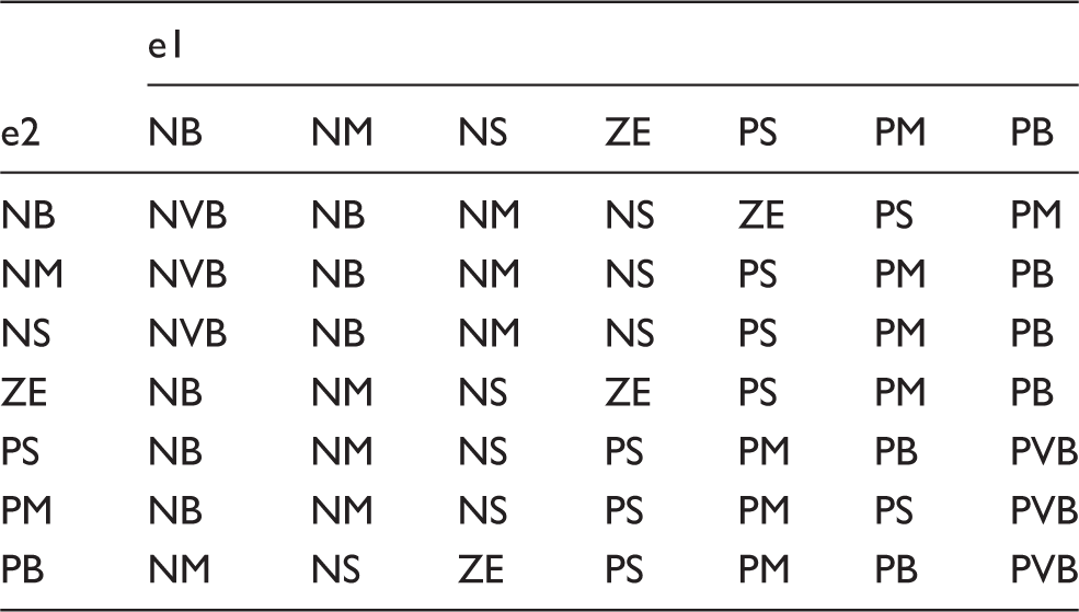
Some of the rules are given below
If error 1 is NB and error 2 is NB then output is NVB
If error 1 is NB and error 2 is PB then output is NM etc.
System parameters

7. Simulation results
The APF circuit using a neural reference generator, fuzzy logic and linear reference generator are established in a Matlab Simulink environment. The system parameters used in these simulations are provided in Table 1. In a system with supply voltage 230 V, 50 Hz is used. The DC reference voltage is set at 350 V. The filter inductor is 15 mH and the DC bus capacitor is 1 mF. This control system is able to detect and eliminate most of the harmonics present in the source current. The nonlinear load consists of a series resistor Rs with an uncontrolled bridge rectifier connected to a capacitor C and a resistive load R.
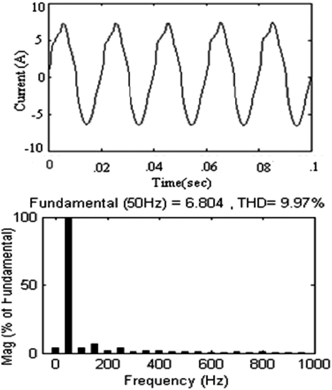
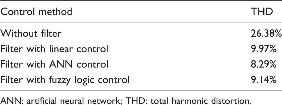
A PI controller for the voltage loop has been implemented to maintain the proper magnitude of the DC side voltage. The rectifier is connected to the AC supply. It draws a current which is distorted and consists of high frequency harmonic components. The proposed soft computing control strategy and linear controller have been verified in Matlab Simulink and results are compared. These results reveal that when using neural controller the magnitude of the harmonic components is considerably reduced at the grid current. The proposed neural control system is able to detect the largest load harmonics and to compensate them properly. Figure 7 shows the distorted current waveform when a nonlinear load is connected across the grid. Through the analysis of the waveforms given, it is clear that THD of grid current is 26.38% when the load is connected. It is reduced to 9.97% by the use of APF with linear control scheme. It is shown in Figure 8.
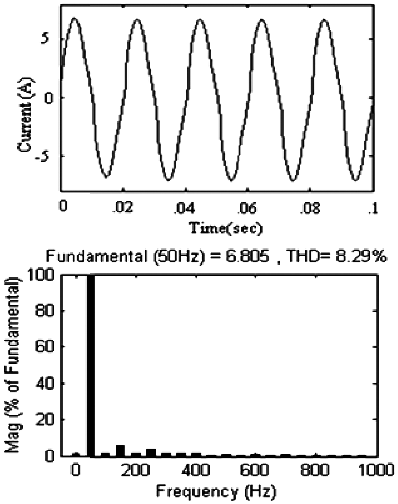
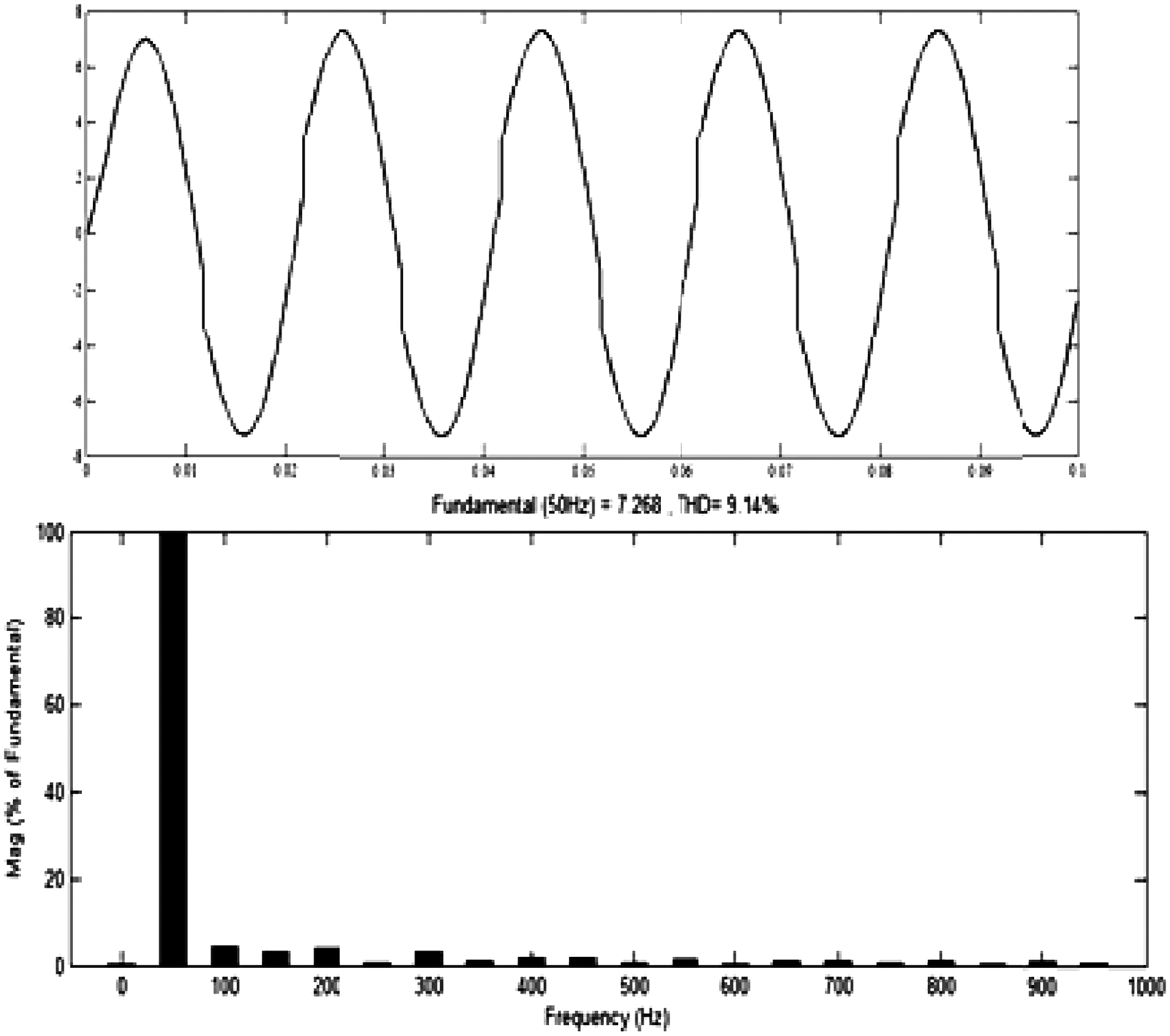
Figure 9 shows that the neural controller is able to reduce these harmonics further, to 8.29%. Compared to the linear controller proposed neural controller and fuzzy logic controller have the advantage of an increased overall efficiency with their high learning rate. The fuzzy logic controller reduces the Total Harmonic Distortion (THD) of the source current to 9.14% as shown in Figure 10. It can adapt itself to compensate for variations in the nonlinear current or nonlinear loads. Higher order harmonics are attenuated very efficiently using the neural controller. Table 3 gives the comparison of the control methods.
Grid current waveform and fast Fourier transform analysis without filter. Grid current waveform and fast Fourier transform with filter using linear reference generator. Grid current waveform and fast Fourier transform analysis with filter using neural reference generator. Grid current waveform and fast Fourier transform analysis with filter using fuzzy logic controller. Comparison of simulation results ANN: artificial neural network; THD: total harmonic distortion.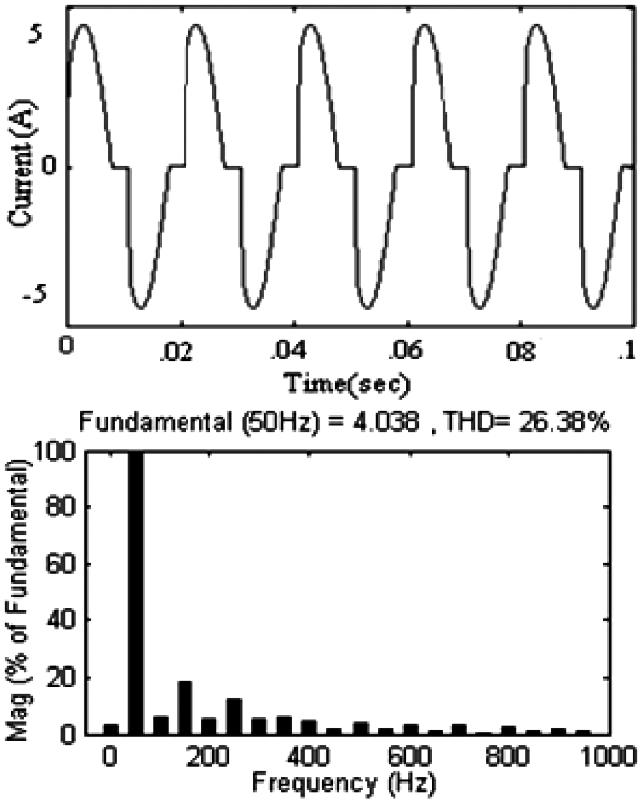
8. Conclusions
In this paper a comparative performance analysis of control methods for an APF has been presented. The proposed controller has been designed to mitigate mainly the third, fifth, seventh, and ninth harmonics. The shunt active filter has been used to compensate a nonlinear load harmonic current. The filter function is made adaptive versus the grid parameter fluctuations. The inverter of the shunt active filter is current controlled by a PI controller. The reference signal is given by different soft computing techniques. Compared to a linear current control scheme, neural and fuzzy controllers have high attenuation against high order harmonics. In linear current control the conventional PI control loop that regulates the average level of the filter capacitor voltage and a resonant selective harmonic compensator are used. This controller is compared with the neural network and fuzzy logic controller which avoids the tedious mathematical operations that are involved and simplifying the final control configuration. These control methods are very effective in mitigating the current harmonics. The source current harmonics are reduced to an acceptable level. Reactive power compensation and power factor are improved. These methods can be used for power quality improvement in industrial drives and power supply systems.
Footnotes
Acknowledgment
We would like to thank the management of Kumaraguru College of Technology and Jawaharlal Nehru Technological University, Hyderabad for providing facilities and valuable support.
Funding
This research received no specific grant from any funding agency in the public, commercial, or not-for-profit sectors.