
Abstract
In recent years, it has been remarkable to see the increasing number of studies related to the theory and application of fractional-order controllers, especially PIλDμ controllers, in many areas of science and engineering. Research activities are focused on developing new analysis and design methods to ensure robustness in new or classical control problems. In this paper, we investigate switching systems. A frequency-domain design method is developed for switching systems for both integer- or fractional-order controllers, taking into account specifications regarding performance and robustness and ensuring the quadratic stability of the controlled system. Some examples are given to show the applicability and effectiveness of the proposed tuning method.
1. Introduction
In recent years, the study of switching systems has received growing attention. Switching systems are a class of hybrid dynamical systems consisting of a family of continuous (or discrete) time subsystems and a rule that orchestrates the switching between them (see e.g. Liberzon, 2003; Sun and Ge, 2005b). The widespread application of such systems is motivated by increasing performance requirements, and by the fact that high performance control systems can be realized by switching between relatively simple linear time invariant (LTI) systems. However, the potential gain of switching systems is offset by the fact that the switching action introduces behaviour in the overall system that is not present in any of the composite subsystems. A survey of the main problems in the stability and design of switching systems was reported in Liberzon and Morse (1999), Sun and Ge (2005a) and Xiang and Xiao (2011). There are many methodologies and approaches developed in the switching systems theory in order to mitigate some problems encountered in practice (refer to Dong, 2011, and the references therein for a current review). However, despite much effort, relatively little work can be found in the literature from a robustness point of view.
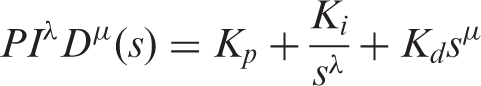
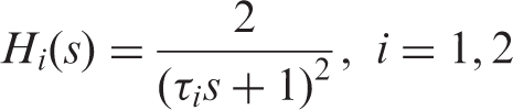
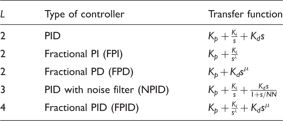
The widespread use of PID controllers has motivated many researchers to look for better design methods or alternative controllers for many years. As reported, for example in Aström and Hägglund (2006), more than 90% of the control loops are PID-type. The generalization of the PID controller to noninteger order, namely PIλDμ, was proposed by Podlubny (1999), whose transfer function, in general form, is given by
Given this context, the objective of this paper is to develop a frequency-domain method to design robust controllers, of both integer- or noninteger-order, for switching systems, given a set of specifications and ensuring the quadratic stability of the controlled system. A preliminary version of this paper can be found in HosseinNia et al. (2012a).
The remainder of this paper is organized as follows. Section 2 provides some fundamentals for the quadratic stability of switching systems, as well as the statement of the problem under consideration. Section 3 addresses the tuning method for the design of robust controllers for switching systems. Three examples are given in Section 4 to show the effectiveness of the developed method. Finally, Section 5 draws the conclusions of this paper.
2. Preliminaries
In this section, some conditions of the quadratic stability of switching systems will be recalled, specifically the frequency domain method introduced in Kunze et al. (2008), which will be useful to present the design method in Section 3. The problem for the class of systems under consideration will also be stated.
2.1. Stability of switching systems
Consider a switching system as

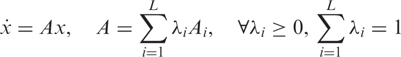
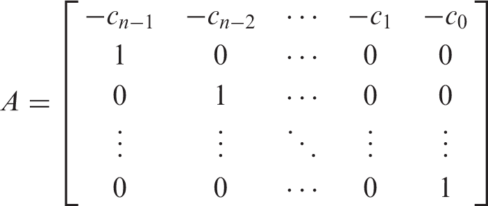
A characteristic polynomial of order n of system (2) can be given by

With definitions above, some important stability conditions of switching systems are offered next:
Quadratic stability (Boyd et al., 1994). A system described by (3) is quadratically stable if and only if there exists a matrix P = PT > 0, P ∈ ℝn×n, such that
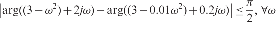
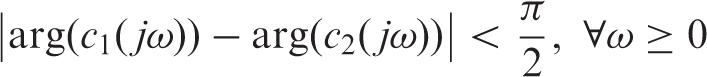
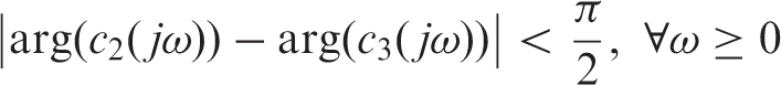
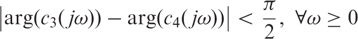
Quadratic stability in frequency domain (Kunze et al., 2008). Consider c1(s) and c2(s), two stable polynomials of order n corresponding to the subsystems c1(s)/c2(s) and c2(s)/c1(s) are strictly positive real (SPR); A1 and A2 are quadratically stable, which means that ∃P = PT > 0 ∈ ℝn×n such that

2.2. Problem statement
It is well known that a switching system can be potentially destabilized by an appropriate choice of switching signal, even if the switching is between a number of Hurwitz-stable closed-loops systems. Even in the case where the switching is between systems with identical closed-loop characteristic polynomials, it is sometimes possible to destabilize the switching system by means of switching (Leith et al., 2003). Likewise, the concept of robustness with respect to parameter variations is well defined for LTI systems. However, this issue is somewhat more difficult to quantify for switched linear systems. In particular, robustness may be defined with respect to a number of design parameters, including not only the parameters of the closed-loop system matrices, but also the switching signal.
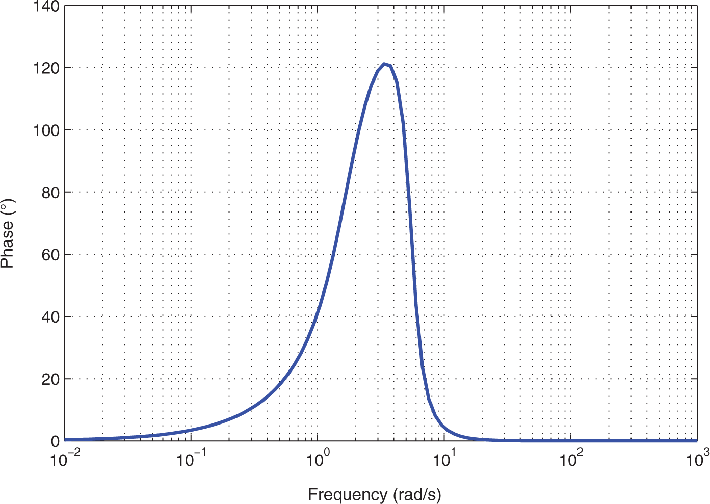
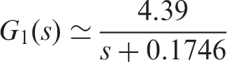
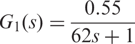
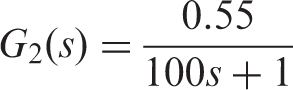
Let us illustrate the importance of designing a robust controller for switching systems by means of a particular example. Consider a switching system given by the following second-order transfer function:
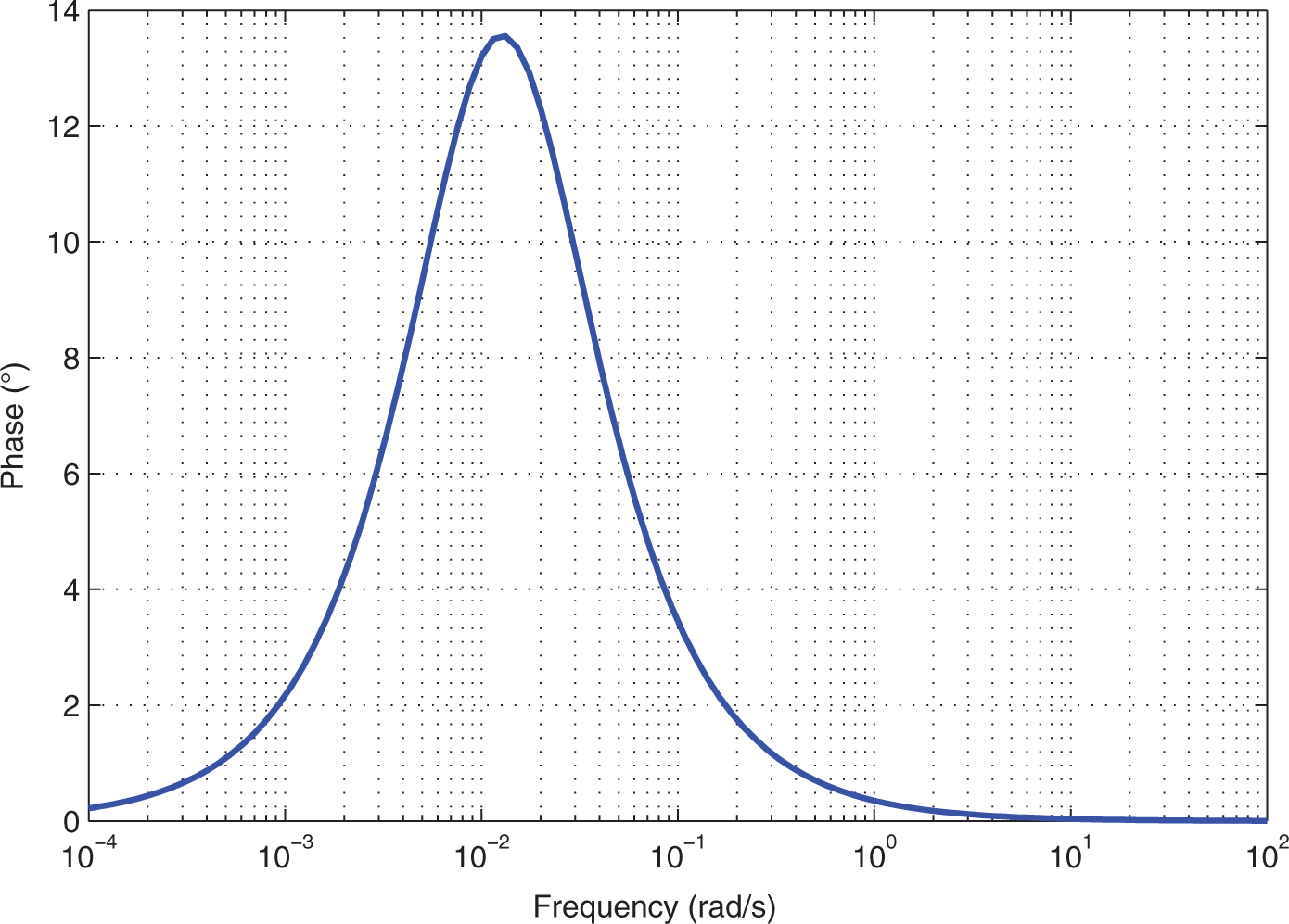
Bode plot of the controlled subsystems H1 and H2. Phase difference between the two characteristic polynomials of the closed-loop subsystems H1 and H2.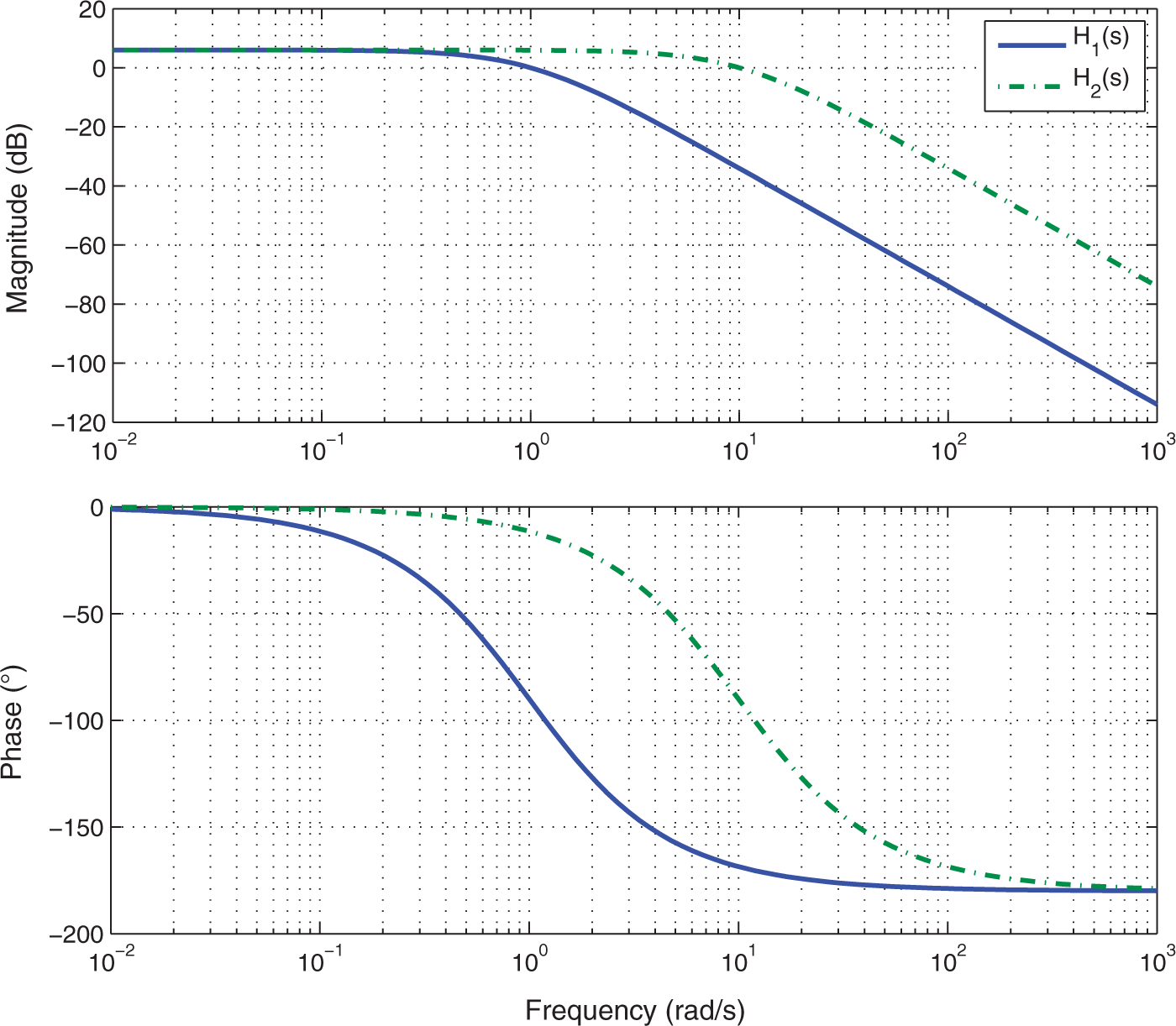
3. Design method
As commented in the introduction, the objective of this paper is to design controllers for switching systems so that the system fulfills different specifications regarding performance and robustness, while ensuring its quadratic stability. A scheme of the control approach is shown in Figure 3 for a general system G
i
(s), i = 1, 2, … , L.
Scheme of the controlled system.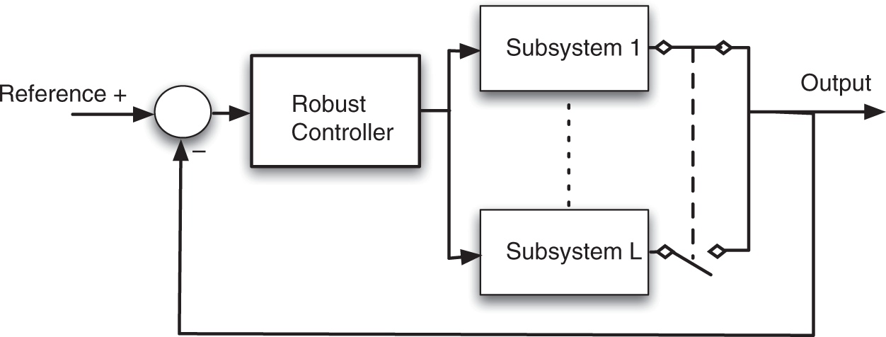
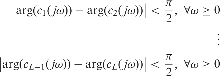
Specifications related to phase margin, gain crossover frequency and output disturbance rejection are going to be considered in this design method. Indeed, other kinds of specifications can be met, depending on the particular requirements of the application. It should be noticed that, apart from these design specifications, which can change with the application, the stability conditions have to be also fulfilled. Actually, if the number of subsystems which constitute the system to be controlled is L, there are L − 1 stability conditions to be fulfilled. Therefore, denoting the number of specifications as N, a controller with L + N − 1 parameters is required in order to fulfill all given specifications and the stability conditions.
Consider G
n
as a subsystem with the worst conditions with regards to each specification and assume that the phase margin and gain crossover frequency of a subsystem G
n
are denoted by φ
m
n
and ω
cp
n
, respectively, where c
i
, i = 1, 2, … , L, are the characteristic polynomials of each closed-loop subsystem and K(jω) is the controller to be tuned. Thus, the design problem is formulated as follows:
Frequency domain specifications:
Phase margin:
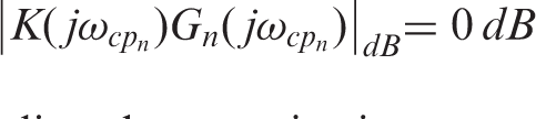
Gain crossover frequency:
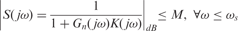
Output disturbance rejection:
Stability conditions:

Type of switching system and possible controllers when N = 2
To determine the controller parameters, the set of nonlinear equations (7)–(10) has to be solved. To do so, the optimization toolbox of Matlab can be used to work out the best solution with minimal error. More precisely, the function FMINCON is able to find the constrained minimum of a function of several variables. It solves problems of the form min x f(x) subject to C(x) ≤ 0, C eq (x) = 0 and x m ≤ x ≤ x M , where f(s) is the function to minimize; C(x) and C eq (x) represent the nonlinear inequalities and equalities respectively (nonlinear constraints); x is the minimum we are looking for; and x m and x M define a set of lower and upper bounds on the design variables, x.
In this particular case, the specification (7) will be taken as the main function to minimize, and the rest of specifications (i.e. (8)–(10)) will be taken as constraints for the minimization, all of them subjected to the optimization parameters defined within the function FMINCON. The success of this optimization process depends mainly on the initial conditions considered for the parameters of the controller.
4. Examples
This section gives some examples of application of the proposed method for designing robust and quadratically stable controllers for switching systems. Specifically, three cases will be considered next for different numbers of design specifications and systems with different numbers of subsystems: the velocity control of a car, the control of a switching system with L = 4 given two design specifications, and the velocity control of a servomotor given three design specifications.
Example 1
Velocity control of a vehicle with first-order dynamics given two design specifications.
In HosseinNia et al. (2011, 2012b) we proposed a hybrid model of a vehicle taking into account its different dynamics when accelerating and braking as follows:
From the viewpoint of the comfort of the car's occupants, phase margin and crossover frequency has to be chosen around 80 ° and 0.8 rad/s, respectively, in order to obtain a smooth closed-loop response with an overshoot close to 0. Therefore, given two specifications (N = 2) and two subsystems (L = 2), controllers with three parameters are required for this application. In particular, two different three-parameter controllers are designed: a fractional PI (FPI) controller and a traditional PID controller, both of the forms given in Table 1. Solving the set of equations (7)–(10) for the previous specifications, the parameters of both controllers are:
FPI: K
p
1
= 0.15, K
i
1
= 0.07 and α = 0.71; PID: K
p
2
= 0.1, K
i
2
= 0.11 and K
d
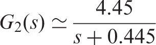
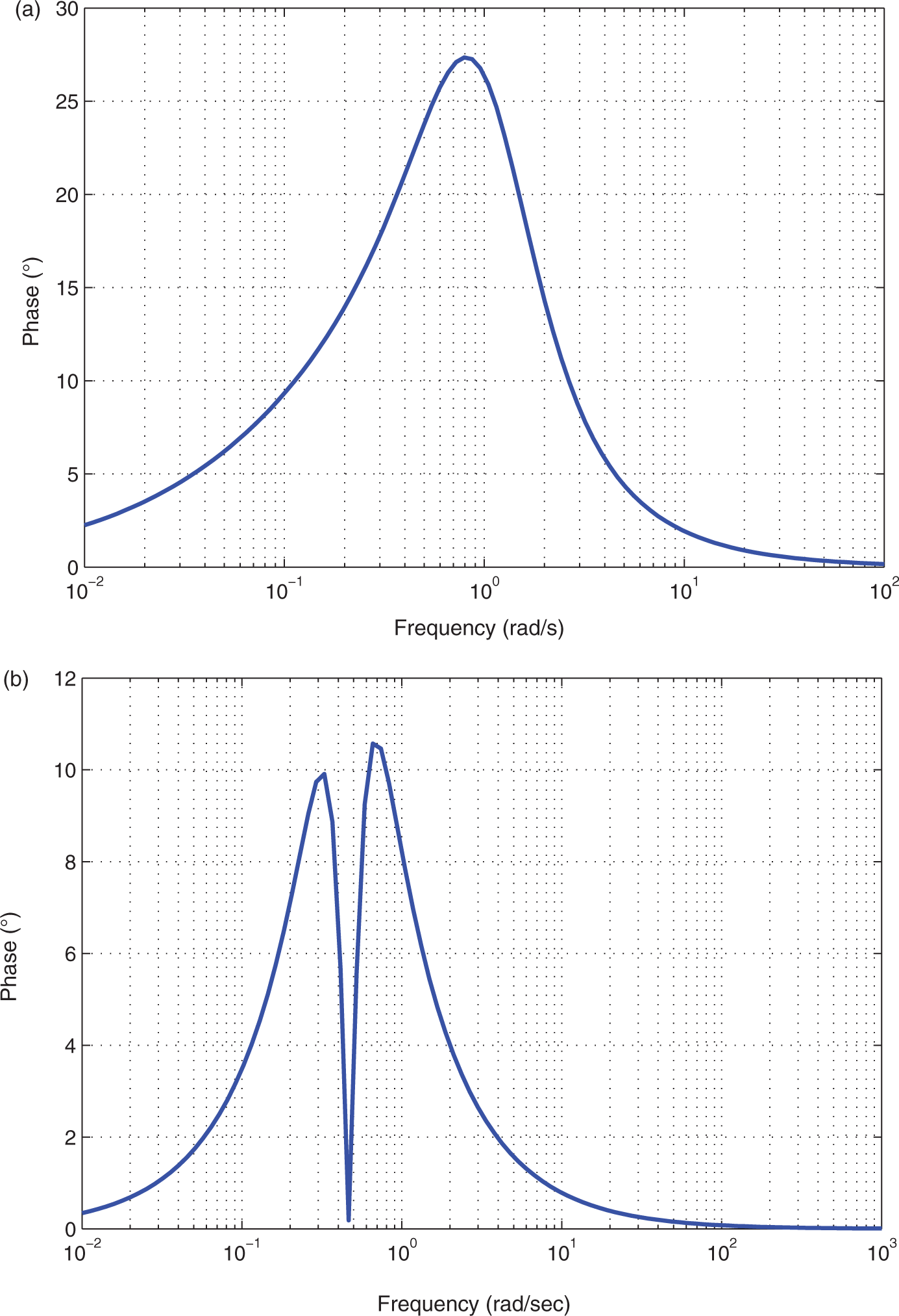
= 0.223. Phase difference between the two characteristic polynomials of the closed-loop system in Example 1 when applying (a) FPI (b) PID. Bode plots of the controlled system in Example 1 when applying (a) FPI (b) PID.
Figure 4 shows the frequency response of the controlled car when applying the FPI and PID controllers. As can be seen, the design specifications are fulfilled for both subsystems for both designed controllers: the phase margin obtained with the FPI is even higher than 80°. An important issue that should be noted is that the system controlled with the PID controller has constant magnitude at high frequencies, which may cause the system to be sensitive to high frequency noises and consequently lead to instability. The phase difference between the two characteristic polynomials of the closed-loop controlled subsystems for both cases is shown in Figure 5. It is observed that the maximum phase differences are 27.35° and 10.57° when using the FPI and PID, respectively, so the controlled system is quadratically stable in both cases.
To show the system performance in time domain, Figure 6 depicts a manoeuvre which simulates the car's acceleration to 20 km/h and, after that, the braking to 0 km/h (stopping completely) for different switching, including a comparison of its velocity for the FPI and PID cases. As observed in this figure, the car has an adequate performance for both the throttle and the brake actions when applying the FPI controller (dash-dotted black line), achieving the reference velocity in a suitable time and without overshoot in both cases. Although both controllers fulfilled the specifications, the response when using the PID (dashed red line) has a considerabley high value of overshoot. As a result, it can be said that the occupants' comfort is guaranteed when applying the proposed FPI controller.
Time response of the controlled system with both FPI and PID during random switching.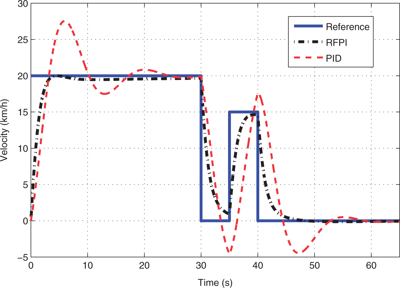
Example 2
Control of a switching system with L = 4 given two design specifications.
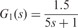
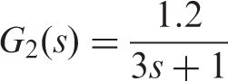
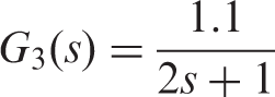
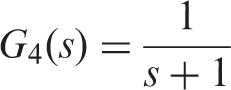
Now consider a switching system given by
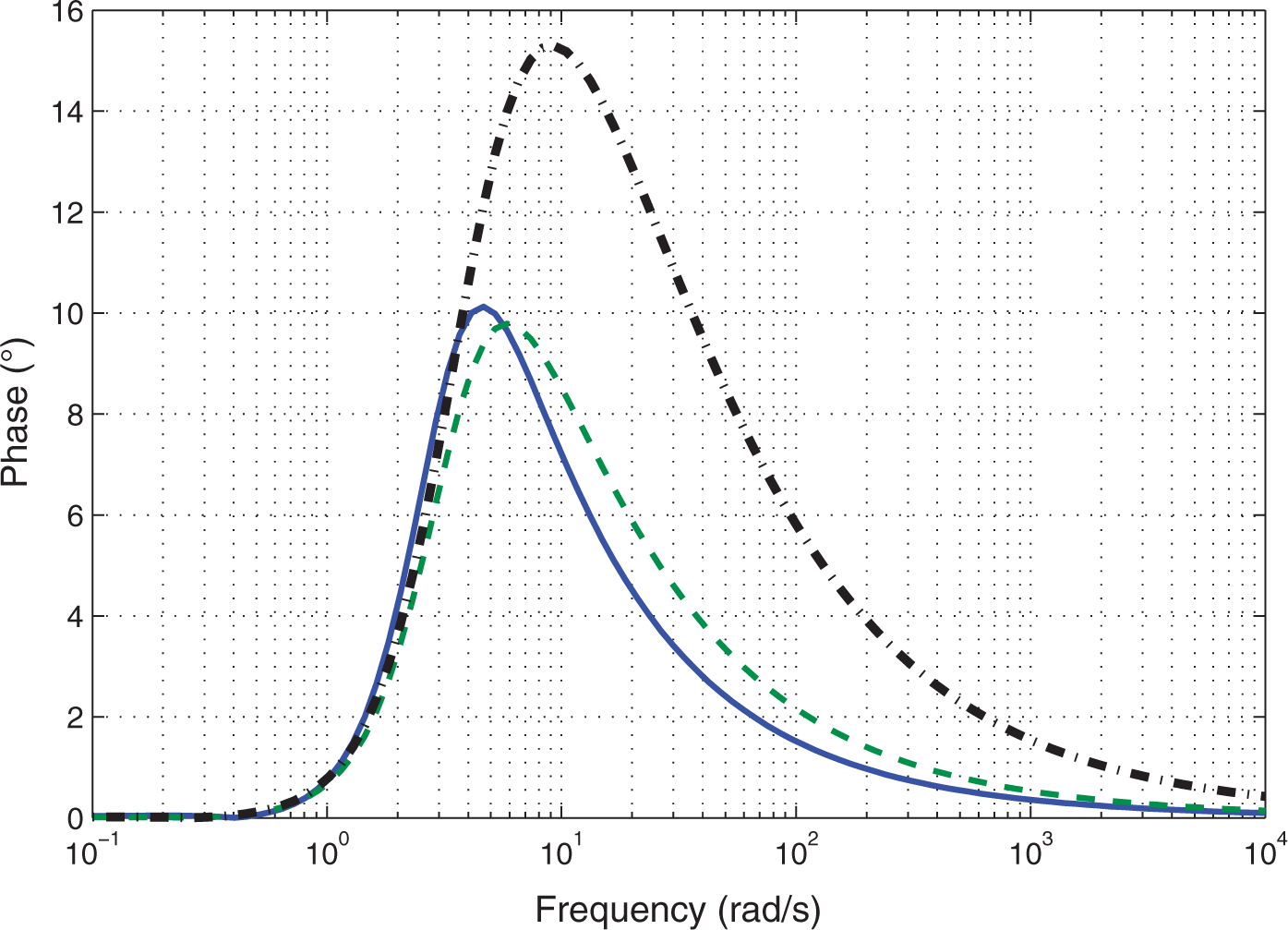
Figures 7 and 8 show the Bode plot and the phase difference, respectively, between each pair of subsystems. It is obvious that the controlled system fulfills the design specifications (ω
cp
> 5 rad/s and φ
m
> 80°) and is quadratically stable. As can be seen, the worst case corresponds to the first subsystem, but is still within the margin of the specifications.
Bode plot of the controlled system in Example 2 when applying FPID.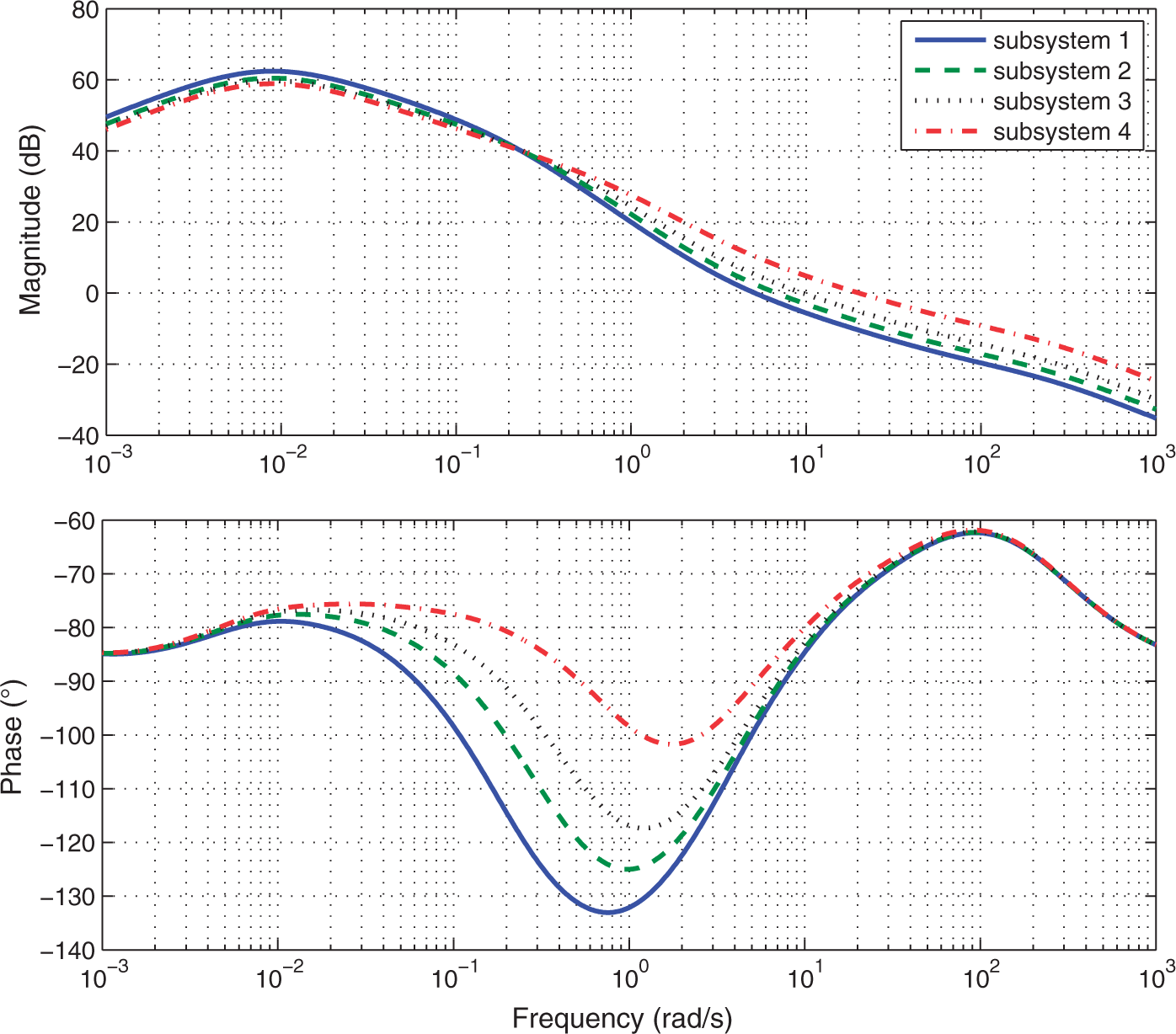
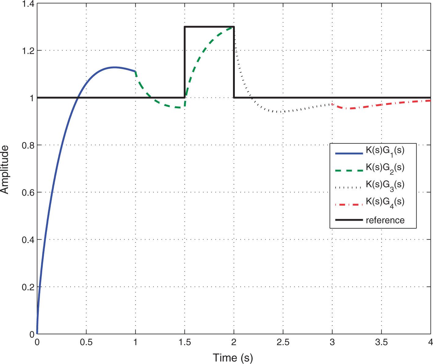
In order to show the performance of the system by applying the designed controller, the closed-loop response is simulated for constant and variable references, as shown in Figures 9 and 10. It can be observed that all the subsystems fulfill the settling time less than 2 s.
Step response of the system in Example 2 for constant reference. Step response of the system in Example 2 for variable reference. Each color is related to the subsystem which is activated, which shows the controller maintains its stability during the switching.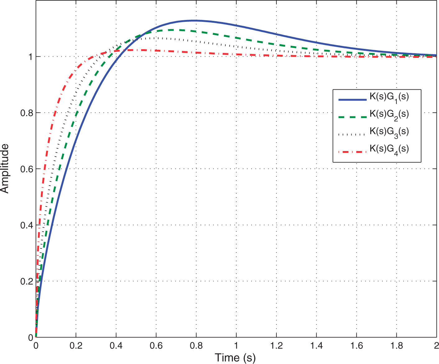
Example 3
Velocity control of a servomotor given three design specifications.
Let us now consider the velocity of a servomotor described by
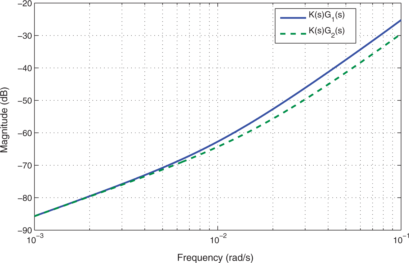
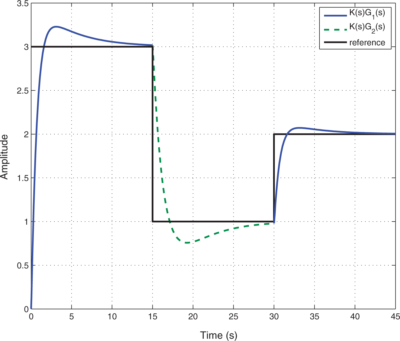
The fulfillment of the design specifications and stability is proved by Figures 11–13, which represent the Bode plot, the phase difference of closed-loop polynomials and the sensitivity function, respectively. Finally, Figure 14 shows the time response of the controlled system for variable reference. It can be observed that its performance is adequate, even during switching.
Bode plot of the controlled system in Example 3 when applying NPID. Phase difference of characteristic polynomials of the closed-loop system in Example 3. Sensitivity function S in Example 3. : Step response of the system in Example 3 for variable reference.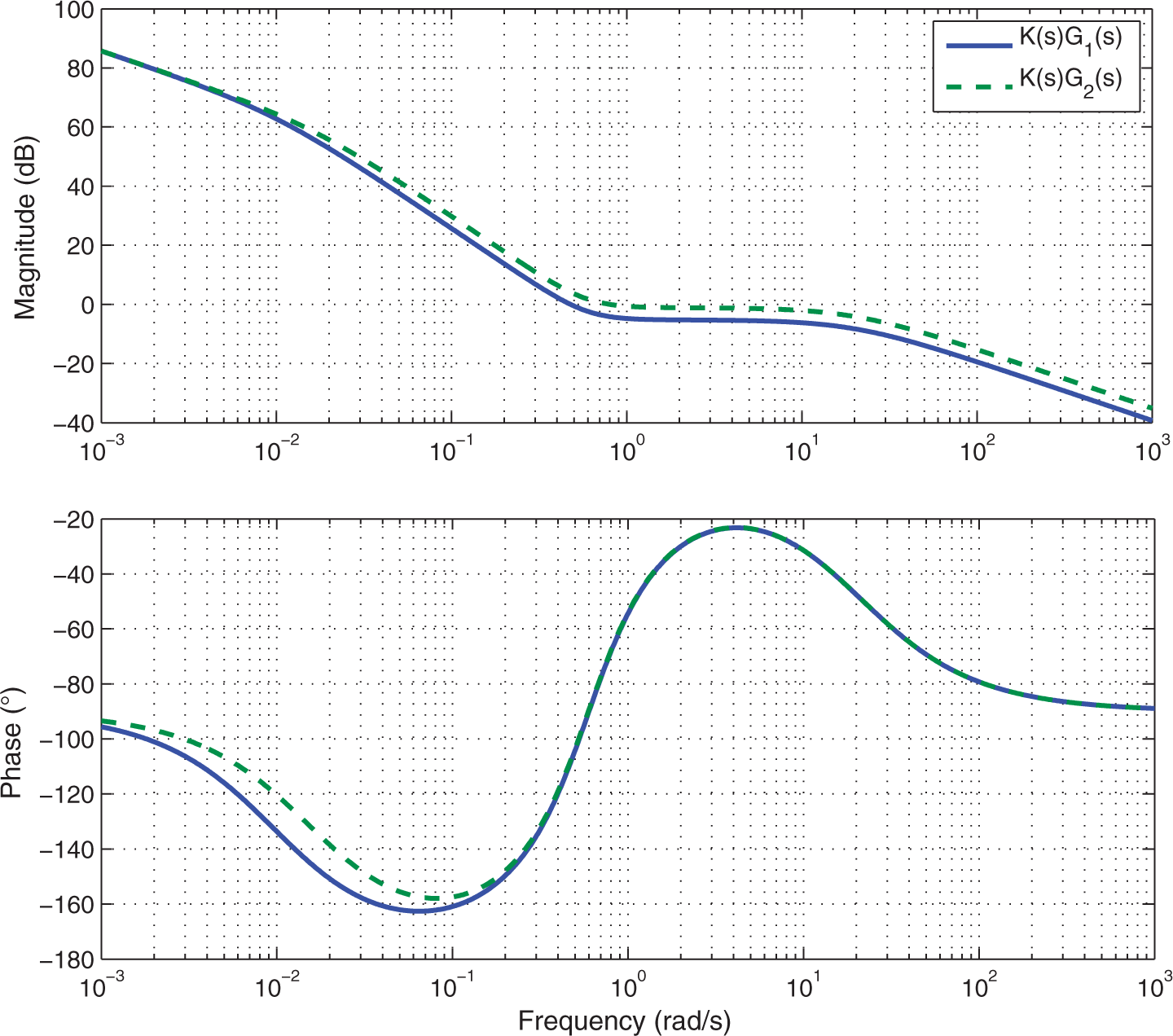
5. Conclusion
This paper has addressed the design of robust controllers for switching systems in frequency domain considering specifications regarding performance and robustness and ensuring the quadratic stability of the controlled system. Three examples were given to show the effectiveness of the proposed tuning method for different kinds of switching systems and for different numbers of specifications to be fulfilled. In particular, different integer- and fractional-order controllers were designed to fulfill a set of desired specifications ensuring the quadratic stability of the switching systems.
In future work, we will focus on the validation of the proposed method in a real application.
Footnotes
Funding
This work was supported by the Spanish Ministry of Science and Innovation under the project DPI2009-13438-C03.