In this paper, reflection and refraction phenomena are studied for a three-dimensional plane quasi-P wave incident at the interface between distinct triclinic half spaces. A method has been developed to find the analytical expressions of all the phase velocities of reflected and transmitted quasi-P (qP), quasi-SV (qSV), and quasi-SH (qSH) waves. Closed form expressions for the amplitude ratios of reflection and transmission coefficients of qP, qSV, and qSH waves are also obtained. These expressions are computed numerically for a given set of data and the velocity distributions and variation of reflection and transmission coefficients with polar and azimuthal angle of incidence are shown graphically using two-dimensional single and double axes graphs. Surface plots of velocity variations of different reflected and transmitted waves are drawn to analyze the combined effect of incident polar and azimuthal angle on velocity distribution. Numerical results presented indicate that anisotropy effects on the reflection and transmission coefficients are significantly different in the three-dimensional case compared to the two-dimensional case. Certain published work has been derived as special cases to illustrate the present technique. Software in MATLAB has been designed to analyze the reflection/transmission phenomena with present geometry in simpler elastic media, such as monoclinic, transversely isotropic, isotropic, etc.
It is known that materials in the Earth are not homogeneous; instead their elastic properties vary with depth and from one region to another. Although these variations may be gradual, there are also discontinuities that separate media with different densities and elastic coefficients. The velocities of seismic waves are influenced by the properties of the layer through which they travel and whenever these waves come across discontinuities between different layers, the phenomena of reflection and transmission take place. In reflection and transmission prospecting, body waves are the source of information used to image the Earth’s interior. A full account of the reflection and transmission of elastic waves was given in the monograph by Achenbach (1976). The problems of reflection and transmission of elastic waves in anisotropic media have been studied by several researchers in the past, notably by Knott (1899), Crampin and Taylor (1971), Crampin (1975, 1977), Keith and Crampin (1977a, 1977b, 1977c), Pal and Chattopadhyay (1984), Auld (1990), Nayfeh (1995), Chattopadhyay and Rogerson (2001), and Sharma (2004).
The elastic properties of a crystalline material depend on its internal structure. The signals of these reflected and refracted waves are not only helpful in providing information about the internal structures of the Earth but also helpful in exploration of valuable materials such as minerals, crystals, and metals. The study of anisotropic elasticity is important for understanding the mechanical behavior of materials. Anisotropy in these materials results from the presence of crystals of particular symmetry or thin laminates. As described in the literature, analytical studies on anisotropic propagation restrict the motion to a fixed (symmetry or arbitrary) plane and, hence, solve a two-dimensional problem. The propagation in an anisotropic media is, in fact, a three-dimensional phenomenon. The presence of mineral orientation, micro-fracturing, or thin layering, or combination of these, in material results in a general anisotropy of arbitrary symmetry. Borejko (1996) discussed the reflection and transmission coefficients for three-dimensional plane waves in elastic media. Chattopadhyay (2007) studied reflection for three-dimensional plane waves in a triclinic crystalline medium.
The wave motion restricted to a symmetry plane represents only a special case of general anisotropy. Study of propagation in any one plane (particularly a symmetry plane) may give no indication of its behavior in the neighboring directions. It is, usually, impossible to extrapolate from a special case of anisotropy to the general case. This demands that anisotropic wave propagation must be studied in three-dimensional spaces and the anisotropy considered should also be of general type, and here comes the motivation of the present problem. Minerals like Vosges sandstone, plagioclase, microcline, rhodonite, turquoise, wollastonite, etc., can be modeled as triclinic materials.
In this paper, we have studied the reflection and transmission of a three-dimensional plane quasi-P (qP) wave incident at the interface of two distinct triclinic crystalline media. Previous works by Chattopadhyay (2004, 2006, 2007) may be obtained as special cases of the present study. A generalized method has been introduced for studying reflection and transmission of waves in highly anisotropic media. Analytical formulas are established to find the direction of the displacement vector for a given propagation vector. The main investigation of the paper is the closed form expressions for the phase velocity and the reflection/transmission coefficients for the reflection and transmission coefficients of qP, quasi-SV (qSV), and quasi-SH (qSH) waves due to an incident qP wave. Numerical results presented indicate that anisotropy effects on the reflection and transmission coefficients are significantly different in the three-dimensional case compared to the two-dimensional case. Software is designed in MATLAB which enables one to utilize the present finding in problems with similar geometry in other elastic media, such as monoclinic, orthotropic, isotropic, etc.
2. Geometry and mathematical formulation of the problem
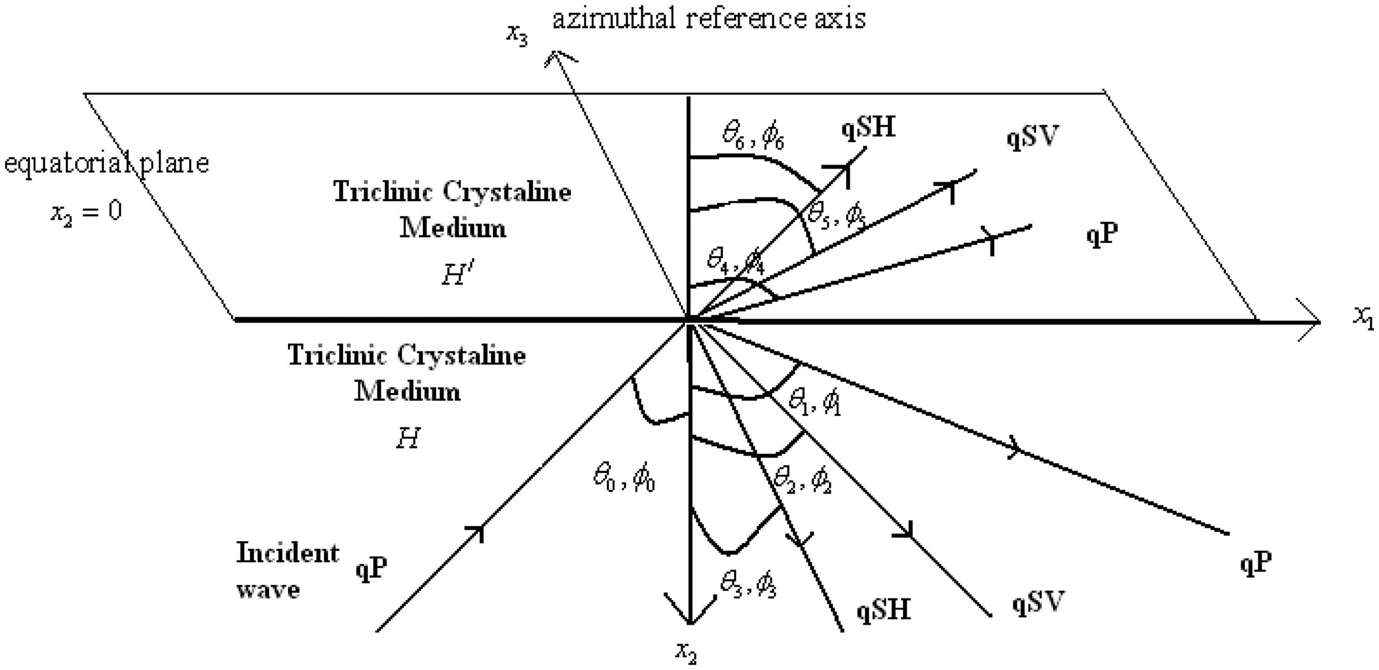
Consider two distinct triclinic elastic half-spaces (Figure 1), namely H and , with different elastic properties. We shall denote the elastic parameters, stresses, and displacement components in medium H without prime and those in medium with primes. The plane represents the free surface and positive x2-axis is directed vertically downwards. Plane is the equatorial plane and positive x3-axis is taken as azimuthal reference axis.
Schematic presentation of the Geometry of the problem.
Further, we consider a three-dimensional plane qP wave whose propagation direction is specified by polar angles and azimuthal angle . This incident qP wave propagating through the medium H and incident at the interface between H and generates three reflected and three refracted (transmitted) qP, qSV, and qSH waves along the direction ( and represent polar and azimuthal angles for the corresponding reflected and transmitted qP, qSV, and qSH waves, respectively). Suffix will be used for the incident qP wave, for reflected qP, qSV, and qSH, while will be used for transmitted qP, qSV, and qSH waves, wherever not mentioned. Let denote the unit propagation vector, cn is the phase velocity and kn the angular wavenumber, where different values of the index n serve to label the various types of waves that occur.
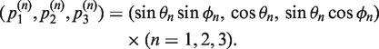
The propagation vector for incident plane qP waves and transmitted quasi waves are given by , and for reflected quasi waves these propagation vectors are defines as
For a three-dimensional plane wave in a homogeneous anisotropic elastic medium, the components of the displacement vector are
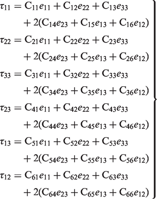
where the symbols , and x3 denote the time and the respective orthogonal Cartesian coordinate axes. Using Hooke’s Law, the stress–strain relations in a triclinic medium are given as
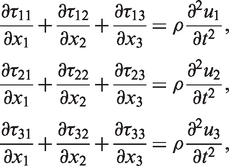
where are the components of the stress tensor in triclinic medium, are stiffness coefficients, and are components of the strain tensor. Both and are symmetric with respect to indices i and j. The equations of motion in the absence of body forces are
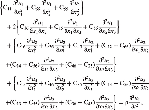
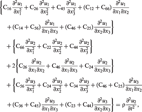
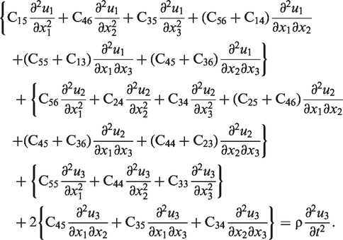
where ρ and denote the mass density and the components of the acceleration, respectively. Using equations (1) and (2), the equations of motion (equation (3)) become
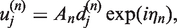
We seek plane wave solutions of the equations of motion (4) of the form
where is the unit displacement vector for corresponding waves, also known as polarization vector, An is the wave amplitude and is the phase function of the plane wave.
Inserting the representation for and u3 from equation (5) in the equations of motion given by equation (4), we obtain the Christoffel equation, which is a system of three homogeneous equations:
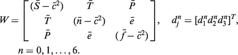
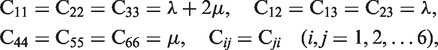
where are the elements of square matrix W of order 3, as defined below
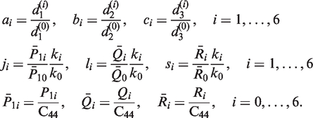
and , , etc, (all the bars are dropped for the sake of simplicity except ), and are defined in the Appendix in equation A.1.
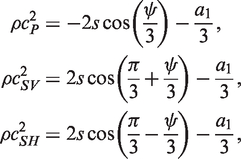
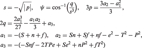
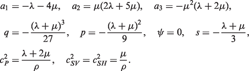
Nontrivial solution of this system explains the propagation of three quasi-waves in an anisotropic triclinic medium. The phase velocities of these quasi-waves in three dimensions are (cf. Chattopadhyay, 2007)
where
The velocities , and are for qP, qSV, and qSH waves respectively. Equation (8) will provide explicit analytical expressions for the three phase velocities of the quasi waves in a triclinic medium.
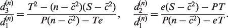
From equation (6) we obtain relations between displacement vectors as
These relations can be used to find the direction of displacement vector for a given propagation vector for all the reflected and transmitted waves. The closed form expressions for phase velocities of quasi waves in triclinic medium given by equation (8) can be used to obtain the same in a simpler medium, such as monoclinic, orthotropic, cubic, etc., by suitable substitution of elastic coefficient.
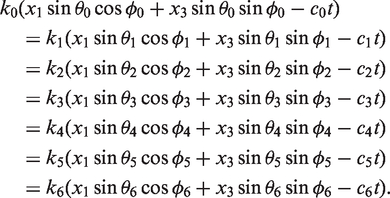
In the plane , displacements and stresses of the incident, reflected, and transmitted waves are represented by
where and the coefficients are defined in the Appendix in equation A.2.
3. Boundary conditions
The displacements and stresses are continuous at the interface ; the mathematical form of boundary conditions can be expressed as:
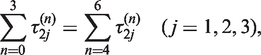
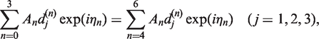
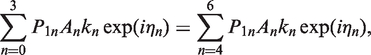
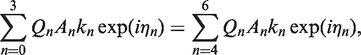
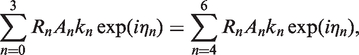
Equations (17)–(20) are valid for all values of x1, x3, and t, so that we have
which gives
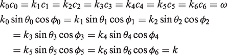
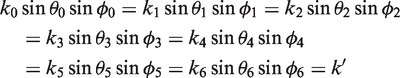
and
where k, k/, and ω are apparent wavenumbers and circular frequency, respectively. It may be interpreted that the phase directions of the incident wave, all reflected waves, and all refracted waves lie in the same plane, implying that .
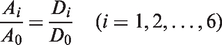
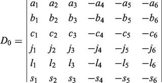
Solving equations (17)–(20), and using relations in equations (21)–(23), we obtain the reflection and transmission coefficients of all the reflected and transmitted qP, qSV, and qSH waves due to a three-dimensional qP wave incident at lower triclinic half space superimposed by another distinct triclinic half space as
where D0 is defined as
and
The determinants can be obtained by replacing all the six elements of the i-th column of D0 by –1 each.
5. Particular cases
5.1. Reflection and refraction of three-dimensional plane quasi-P waves at the interface between distinct monoclinic media
If the reflection and refraction took place between dissimilar monoclinic media with the equatorial plane being the plane of elastic symmetry then the phase velocity of different reflected and transmitted waves can be obtained from equation (8) with following substitution
Similarly reflection and transmission coefficients of all the reflected and transmitted qP, qSV, and qSH waves due to a three-dimensional qP wave incident at lower monoclinic half space superimposed by another distinct monoclinic half space will be given by equation (24) with substitution of elastic coefficients as listed in equation (27). Further, if we take azimuthal angle the given problem reduces to reflection and transmission of two-dimensional planes qP wave between distinct monoclinic media, and thus we obtain results derived by Chattopadhyay (1996).
5.2. Reflection and refraction of three-dimensional plane quasi-P waves at the interface between distinct orthotropic elastic media
Orthotropic elastic media is a simpler class of materials and is defined by nine independent moduli only. These materials have three orthogonal planes of elastic symmetry and as discussed above, the phase velocity of different reflected and transmitted waves in case of distinct orthotropic elastic media can be obtained from equation (8) with following substitution
Similarly reflection and transmission coefficients of all the reflected and transmitted qP, qSV, and qSH waves due to a three-dimensional qP wave incident at lower orthotropic half space superimposed by another distinct orthotropic half space will be given by equation (24) with substitution of elastic coefficients as listed in equation (28).
5.3. Reflection/transmission at the interface between distinct isotropic half spaces
Hence, the result for incident, reflected, and transmitted quasi-P waves in a triclinic medium reduces to that for a P wave in an isotropic medium; similarly, the result for other quasi transverse waves reduces to that for a shear wave.
5.4. Other particular cases
Certain published work can be derived as special cases of the present problem. For example if we restrict our attention to coefficients of reflected waves only by considering reflection at a traction-free boundary, we obtain the results of Chattopadhyay (2007). When azimuthal angle the given problem reduces to reflection and transmission of a two-dimensional planes qP wave between distinct triclinic media and thus we obtain results derived by Chattopadhyay (2004). Furthermore, considering reflection at a traction-free boundary, we obtain results derived by Chattopadhyay (2006).
The current geometry can also be analyzed in other simpler elastic media, such as trigonal, tetragonal, transversely isotropic, and cubic media, by using the results of the present problem and suitably substituting the elastic parameters (Aki and Richards, 2002).
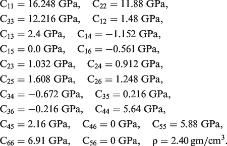
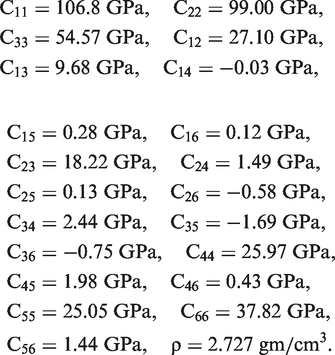
The incident polar angle and azimuthal angle are taken as wherever not mentioned. In the legend of the figures, the dimensionless phase velocity of reflected and transmitted waves are shown by , while reflection and transmission coefficients for reflected and transmitted waves are shown by and , respectively.
In Figures 2–4 we have shown the variation in dimensionless phase velocities for different reflected and transmitted quasi waves against incident polar angles. Similar graphs can be drawn for the effect of incident azimuthal angle. In order to analyze the combined effect of incident polar and azimuthal angle we have drawn surface plots of dimensionless phase velocities of different reflected and transmitted waves in Figures 5–7. We have drawn modulus of reflection and transmission coefficients for all the reflected and transmitted waves with respect to the incident polar and azimuthal angle in Figures 8 and 9, respectively. Finally, in Figure 10, we have shown a snapshot of the software developed in MATLAB showing the velocity distribution and reflection coefficient for a reflected qP wave for a particular model.
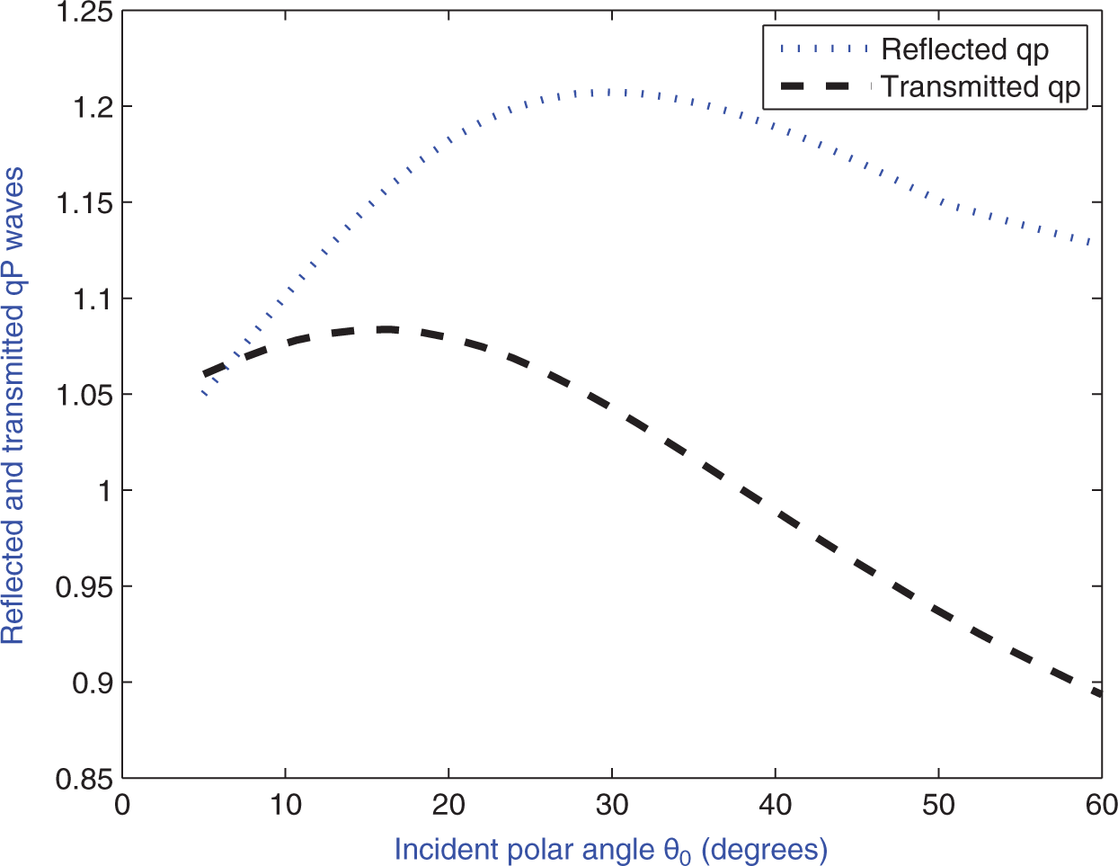
Variation in dimensionless phase velocities for reflected and transmitted qP waves against incident polar angle φ0 at φ0 = 30°.
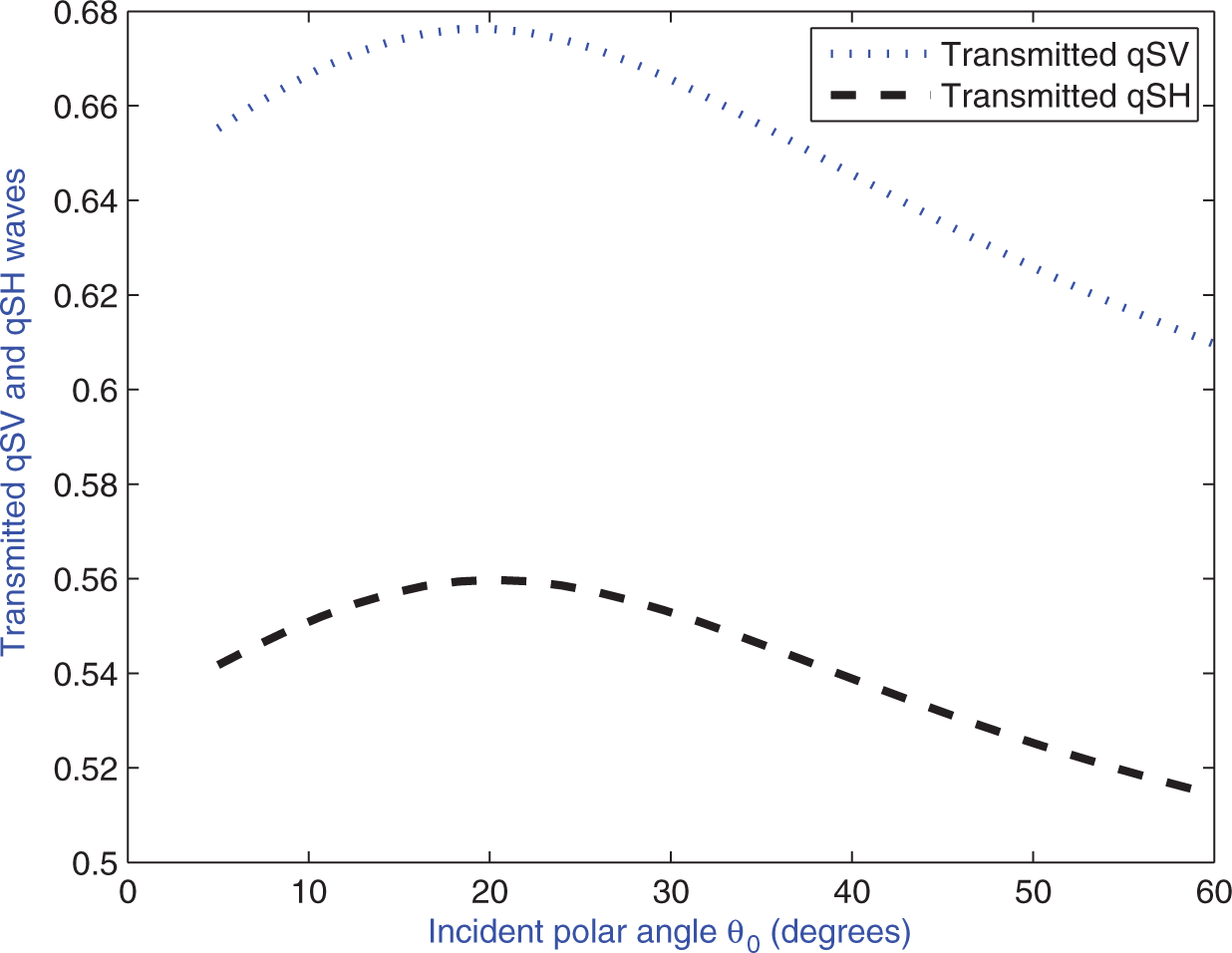
Variation in dimensionless phase velocities for transmitted qSV and qSH waves against incident polar angle φ0 at φ0 = 30°.
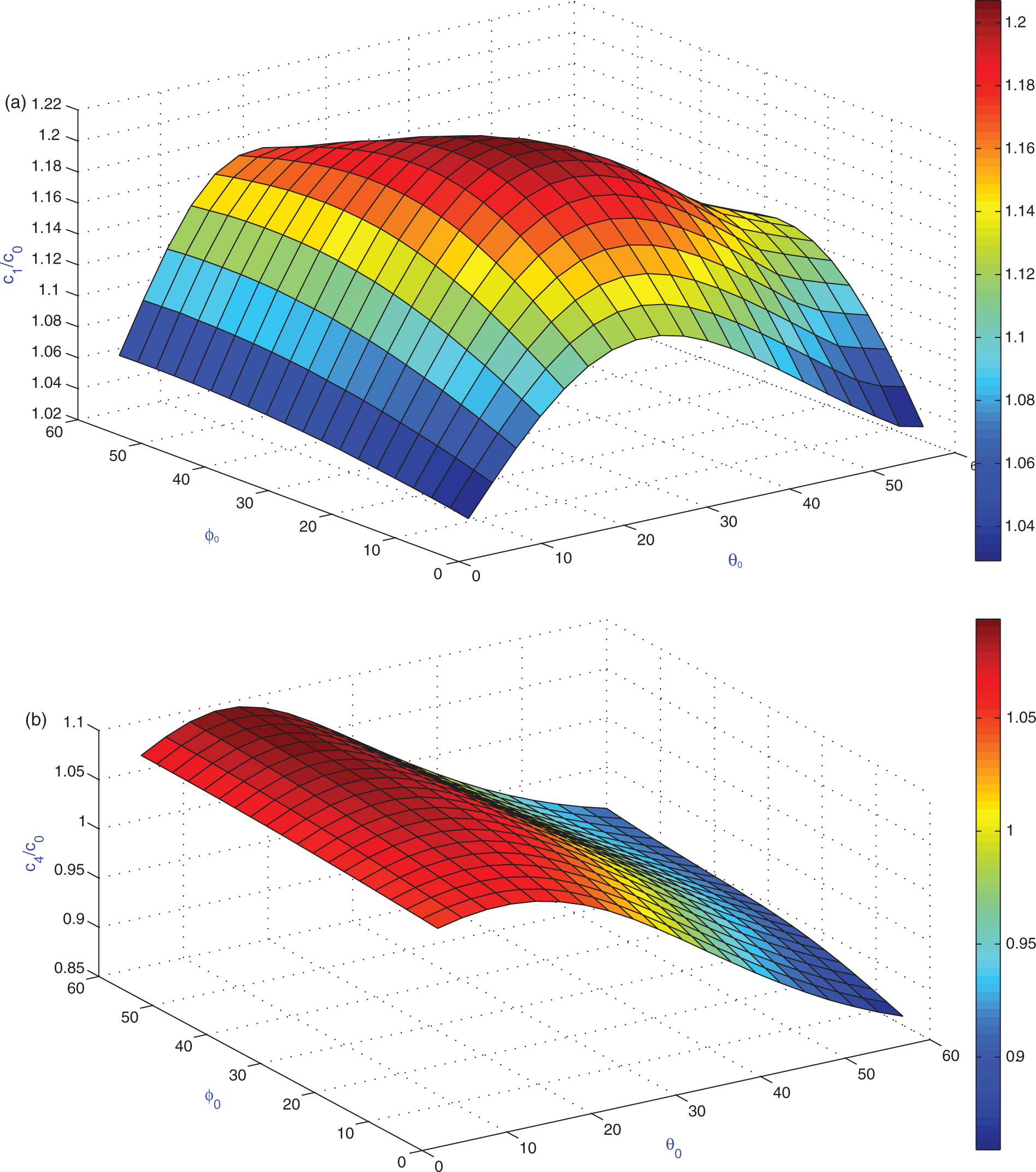
Surface plot for dimensionless reflected and transmitted qP wave velocity against incident polar and azimuthal angle.
Surface plot for dimensionless reflected and transmitted qSV wave velocity against incident polar and azimuthal angle.
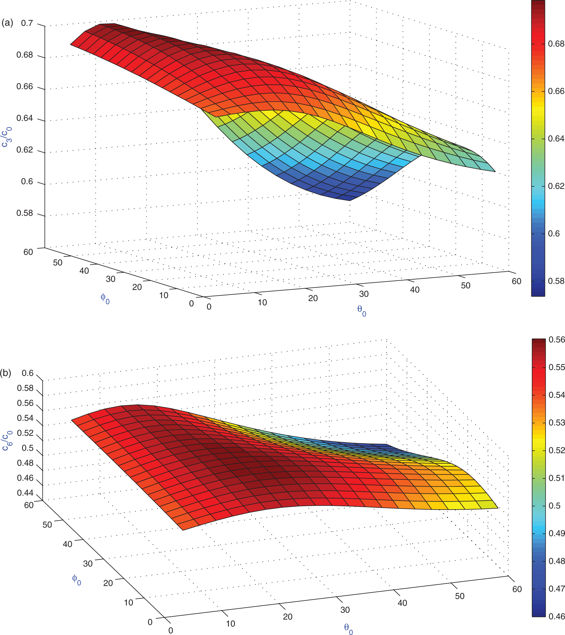
Surface plot for dimensionless reflected and transmitted qSH wave velocity against incident polar and azimuthal angle.
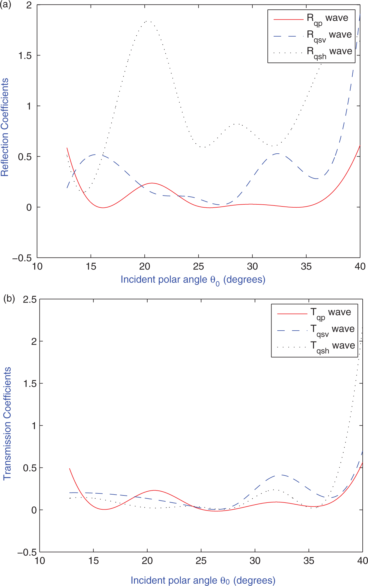
Reflection and Transmission coefficient for corresponding reflected and transmitted waves against incident polar angle.
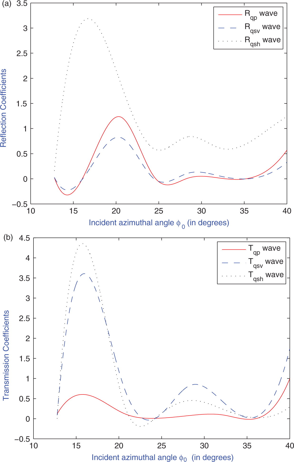
Reflection and Transmission coefficient for corresponding reflected and transmitted waves against incident azimuthal angle.
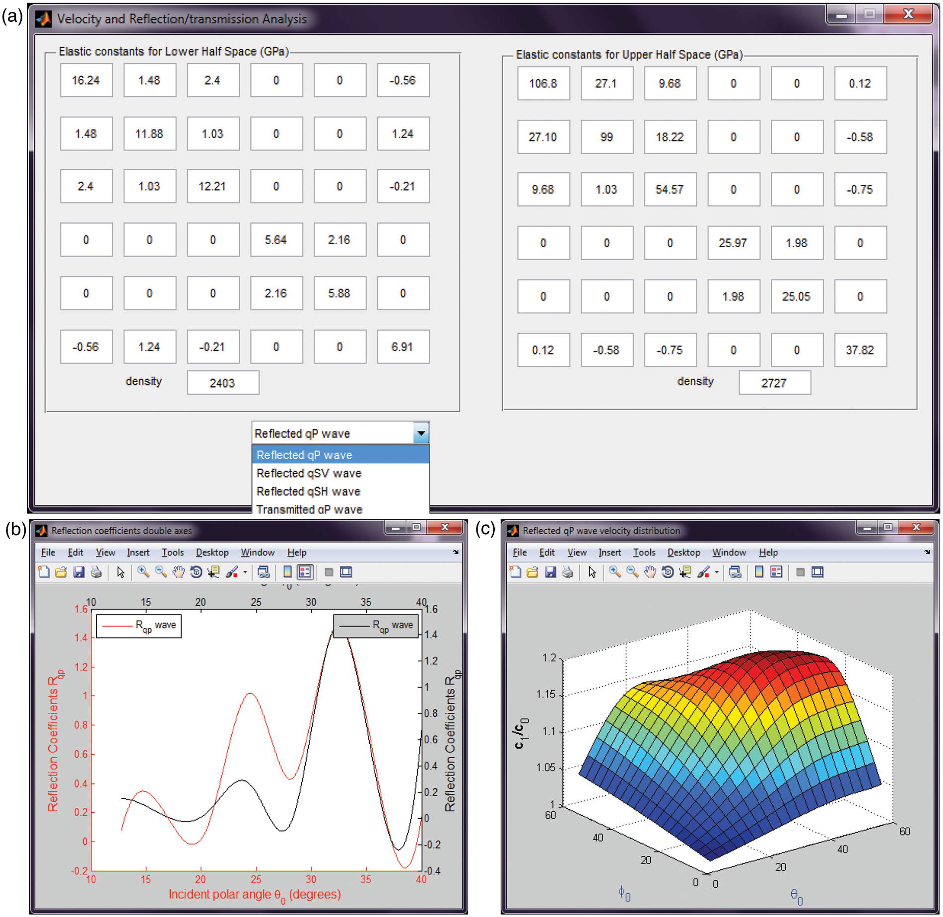
Snapshot of the software showing the velocity distribution and reflection coefficient for user defined data.
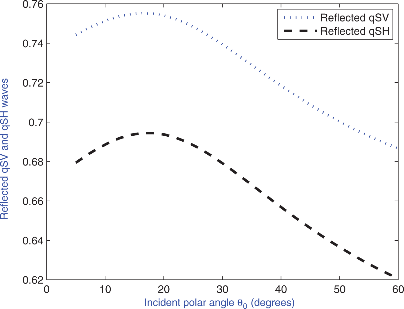
Figure 2 shows the velocity variation in reflected and transmitted qP waves with respect to incident polar angle . It is clear that the velocities of both reflected and transmitted qP waves coincide at grazing incidence but increase with different slopes from here onward and they both attain global maxima at (i.e. when incident polar angle coincides with incident azimuthal angle); thereafter both show a decreasing trend. Figure 3 shows the velocity variation in reflected quasi transverse waves (qSV and qSH) with respect to incident polar angle . It is clear that the velocities of both qSV and qSH waves start with certain value near grazing incidence, increase uniformly until they attain a local maxima at , and thereafter show a decreasing trend. Results for transmitted qSV and qSH waves in Figure 4 show variations similar to those in Figure 3, except for the fact that they attain their global maxima at . Figures 2–4 show that phase velocities of reflected (or transmitted) quasi transverse waves (qSV and qSH waves) are not identical; however, these quasi transverse waves show increasing trend with similar slopes near grazing incidence. These figures also indicate that velocities for all reflected and transmitted waves exhibit a sharp increase near grazing incidence, attain a global maximum at a certain polar angle, and then show decreasing trend near normal incidence. However, the angle of global maxima is different for different quasi waves. Analysis similar to that in Figures 2–4 can also be performed for incident azimuthal angle.
Variation in dimensionless phase velocities for reflected qSV and qSH waves against incident polar angle φ0 at φ0 = 30°.
In order to analyze the combined effect of azimuthal and polar incident angle on velocity variation for all the reflected and transmitted waves, we have drawn surface plot for all reflected/transmitted wave in Figures 5–7. These figures show that, in general, velocities of all reflected and transmitted waves exhibit sinusoidal nature (discussed in previous section) against polar incident angle, while they shows gradual increasing nature against azimuthal incident angle.
Figure 8 (top) shows the variation in , and with respect to incident polar angle at . It is clear that the variation in reflection coefficients and decreases rapidly from certain values at grazing incidence and then increases slightly with increase in angle of incidence from onwards; both and attain local maxima near and show an increasing trend after . on the other hand increases rapidly from certain values at grazing incidence, attains local maxima near , and then decreases gradually with increase in angle of incidence until ; thereafter it increases with point of inflexion near . Figure 8 (bottom) shows the variation in , and with respect to incident polar angle at . It shows that variation in all transmission coefficients (, and ) decreases from certain values at grazing incidence and then increases slightly with increase in angle of incidence until (except which achieve local minima and maxima, respectively, at and ).
Figure 9 (top) shows the variation in , and with respect to incident azimuthal angle at . It shows that variation in reflection coefficients and decreases rapidly from certain values at grazing incidence, reach global minima and maxima at and , respectively. on the other hand increases rapidly near grazing incidence, reaches global maxima and minima at and , respectively. Beyond , all reflection coefficients (, and ) exhibit gradual increasing trend. Figure 9 (bottom) shows the variation in , and with respect to incident azimuthal angle at . It shows that variation in all transmission coefficients (, and ) increases from certain values at grazing incidence and then decreases after . From onwards all transmission coefficients show increasing trend. It also shows that all reflection and transmission coefficients increase near critical azimuthal incidence.
In order to generalize the findings to be applicable for user-defined data and for other simpler media, such as monoclinic, orthotropic, isotropic, etc, we have developed software in MATLAB with a graphical user interface (GUI), a snapshot of which is shown in Figure 10. Users can choose the values of elastic constants for lower and upper half space, as shown in Figure 10 (top). After choosing values of elastic constant one can opt for the analysis of corresponding to reflected or transmitted quasi waves using the popup menu. In the snapshot, we have shown the result for a particular monoclinic medium and the graphs are shown for reflected qP wave. Figure 10 (middle) shows the double axes graphs generated for reflected qP waves, which show the variation in reflection coefficients against incident polar angle (lower x-axis) and incident azimuthal angle (upper x-axis). Left y-axis correspond to against incident polar angle while y-axis on the right hand show variation in against incident azimuthal angle. Figure 10 (bottom) shows the surface plot for the velocity variation of reflected qP wave in the above particular model. Thus, using the present software one can analyze the problems with similar geometry in other simpler media by arbitrary chosen values for elastic constants of the concerned geological media and then see the nature of reflection (transmission) coefficient and velocity variation for a reflected (transmitted) wave chosen from popup menu.
7. Conclusion
Reflection and transmission phenomena of a three-dimensional plane qP wave incident at the interface between distinct triclinic half spaces have been studied in the present paper. Closed form solutions are obtained for velocities and reflection/transmission coefficients for all the reflected/transmitted quasi waves. Thr results of Chattopadhyay (2004, 2006, 2007) are obtained as special cases of the present problem. Moreover, problems with similar geometry in simpler elastic media, such as monoclinic, orthotropic, isotropic, etc, can be analyzed using the results of the present paper and with substitution of elastic constants (Aki and Richards, 2002) in the software generated by MATLAB. These reflection and transmission coefficients and velocity variations are computed numerically and shown graphically for fixed values of relevant parameters using two-dimensional single and double axes graphs. Surface plots of velocity variations of different reflected and transmitted waves are drawn to analyze the combined effect of incident polar and azimuthal angle on velocity distribution. Using the theoretical and numerical results we conclude that
The reflection and transmission phenomena of three-dimensional plane qP wave is more general and hence represent the physical situation more realistically. The amplitude ratios of reflected and refracted (transmitted) curves are significantly different in the three-dimensional case compared to the two-dimensional case. Certain problems are obtained as special cases of the present study.
Velocity variations of all reflected and transmitted quasi waves are significantly dependent on elastic constant and incident polar and azimuthal angles. Velocities of both the reflected and transmitted qP waves coincide at grazing incidence but increase with different slopes from there onward; they both attain global maxima when the incident polar angle coincides with the incident azimuthal angle.
Phase velocities of reflected (or transmitted) quasi transverse waves (qSV and qSH) are not identical; however, these transverse quasi waves show increasing trend with similar slopes near grazing incidence.
Velocities for all reflected and transmitted waves exhibit a sharp increase near grazing incidence, attain a global maximum at a certain polar angle, and then show decreasing trend near normal incidence. However, the angle of global maxima is different for different quasi waves.
In general, velocities of all reflected and transmitted waves exhibit sinusoidal nature against polar incident angle, while they shows gradual increasing nature against azimuthal incident angle.
Modulus of reflection and transmission coefficients of reflected and transmitted waves are also dependent on elastic constants and incident polar and azimuthal angles. These coefficients will be different in different elastic media. In general, all reflection and transmission coefficients increase near critical azimuthal incidence.
GUI (Graphical User Interface) software in MATLAB has been prepared to generalize the result of the study for finding the reflection and transmission coefficients and velocity variation for different reflected and transmitted waves. It can be utilized by assigning different suitable values to elastic parameter and thus it can analyze the problem with similar geometry in other simpler elastic medium with suitably chosen input variables.
The present findings may be helpful in nondestructive testing and influence the sources of information used to image the Earth’s interior, in forecasting geophysical parameters through signal processing, and in seismic data analysis due to more realistic assumption to actual anisotropy of Earth. The present study can also possibly be useful to geophysicists and metallurgists for analysis of rock and material structures through nondestructive testing.
Footnotes
Funding
This research received no specific grant from any funding agency in the public, commercial, or not-for-profit sectors.
References
1.
AchenbachJD (1976) Wave Propagation in Elastic Solids, New York: North Holland.
2.
AkiKRichardsPG (2002) Quantitative Seismology, 2nd ed. California: University Science Books.
3.
AuldBA (1990) Acoustic Fields and Waves in Solids (Volume I), Florida: Keieger Publishing Company.
4.
BorejkoP (1996) Reflection and transmission coefficients for three-dimensional plane waves in elastic media. Wave Motion24(4): 371–393.
5.
ChattopadhyayA (2004) Wave reflection and transmission in triclinic crystalline medium. Archive of Applied Mechanics73: 568–579.
6.
ChattopadhyayA (2006) Wave reflection in triclinic medium. Archive of Applied Mechanics76: 65–74.
7.
ChattopadhyayA (2007) Reflection of three-dimensional plane waves in triclinic crystalline medium. Applied Mathematics and Mechanics28(10): 1309–1318.
8.
ChattopadhyayARogersonGA (2001) Wave reflection in slightly compressible, finitely deformed elastic media. Archives of Applied Mechanics71: 307–316.
9.
ChattopadhyayASahaS (1996) Reflection and refraction of P-waves at the interface of two monoclinic media. International Journal of Engineering Science34(11): 1271–1284.
10.
CrampinS (1975) Distinctive particle motion of surface waves as a diagnostic of anisotropic layering. Geophysical Journal of the Royal Astronomical Society40: 177–186.
11.
CrampinS (1977) A review of the effects of anisotropic layering on the propagation of surface waves. Geophysical Journal of the Royal Astronomical Society49: 9–27.
12.
CrampinSTaylorDB (1971) The propagation of surface waves in anisotropic media. Geophysical Journal of the Royal Astronomical Society25(1–3): 71–87.
13.
KeithCMCrampinS (1977a) Seismic body waves in anisotropic media: reflection and transmission at a plane interface. Geophysical Journal of the Royal Astronomical Society49: 181–208.
14.
KeithCMCrampinS (1977b) Seismic body waves in anisotropic media: propagation through a layer. Geophysical Journal of the Royal Astronomical Society49: 209–223.
15.
KeithCMCrampinS (1977c) Seismic body waves in anisotropic media, synthetic seismograms. Geophysical Journal of the Royal Astronomical Society49: 225–243.
16.
KnottCG (1899) Reflection and transmission of elastic waves with seismological applications. Philosophical Magazine48: 64–97.
17.
MenschTRasolofosaonP (1997) Elastic wave velocities in anisotropic media of arbitrary anisotropy – generalization of Thomson’s parameters α, β, and γ. Geophysical Journal International128(1): 43–64.
18.
NayfehAH (1995) Wave Propagation in Layered Anisotropic Media with Applications to Composites, Amsterdam: Elsevier.
19.
PalAKChattopadhyayA (1984) The reflection phenomena of plane waves at a free boundary in a pre-stressed elastic half-space. Journal of the Acoustical Society of America76(3): 924–925.
20.
RasolofosaonPNJZinsznerBE (2002) Comparison between permeability anisotropy and elasticity anisotropy of reservoir rocks. Geophysics67(1): 230–240.
21.
SharmaMD (2004) 3-D wave propagation in a general anisotropic poroelastic medium: reflection and transmission at an interface with fluid. Geophysical Journal International157(2): 947–958.