






Abstract
A compound track-absorber model with multiple wheels on the rail is employed to study the effects of a rail absorber on the normal wheel–rail contact forces in the frequency domain. Two different absorber models, which are the piecewise continuous absorber and the discrete absorber installed in the middle of the sleeper span, are presented. It can be seen from the calculation results that there are more peaks occurring in the frequency range of 500–1200 Hz due to the wave reflections between the wheels than that of a single wheel–rail interaction. However, these peaks are all suppressed due to the effects of the rail absorber, and there are new peaks appearing at other frequencies while the amplitude of these peaks is relatively small. The peaks in contact force at low frequencies are higher, whereas the peak at pinned-pinned resonance is suppressed.
1. Introduction
When a train runs along a track, the roughness on the rail and wheel tread leads to wheel–rail interaction forces, which induces structural vibration and noise radiation of the two parts. These varying contact forces cause uneven wear on the railhead. The wheel–rail interaction forces leads to rail corrugations, which in turn induces excessive vibrations, causes undue noise radiation, restricts the vehicle speed, and in some cases causes rolling contact fatigue defects when a train runs along the track. In recent years, a number of models have been developed to obtain a better understanding on the formation of the rail corrugation and to propose some feasible treatments of corrugation (Grassie et al., 1982; Hempelmann et al., 1991; Grassie and Kalousek, 1993; Hempelmann and Knothe, 1996; Igeland, 1996; Nielsen, 1999).
Grassie and Kalousek (1993) classified rail corrugations into six groups according to their characteristics and mechanisms. According to track dynamics, it has been found that short pitch corrugation is associated with a constant frequency (Hempelmann and Knothe, 1996), at which the amplitude of wheel–rail contact force reaches a maximum. Simulations by Igeland (1996) have shown that the spectral density of the railhead wear varies with wavenumber (frequency) almost in the same way as the normal contact force does. From the point of view of track dynamics, it is clear that the wheel–rail contact force plays an important role in the formation of short pitch corrugation. A track model with multiple wheels on the rail in the frequency domain has been proposed by Wu and Thompson (2002). In this model, the effects of wave reflections between the wheels and different pad stiffnesses were considered in the calculations. According to the calculation results, it can be concluded that the wheel–rail interaction forces may have several peaks at different frequencies due to wave reflections between multiple wheels and the rail. Also, the wear was found to be more severe, and have shorter wavelength. The wear was proportional to the amplitude of the wheel–rail interaction force (Wu and Thompson, 2005).
A new kind of rail damper was studied to suppress the pinned-pinned resonance, which is mounted between sleepers on the rail (Maes and Sol, 2003). A two-frequency tuned absorber system attached continuously to the rail on each side was also presented in Thompson et al. (2007). In field tests with this system, a reduction of 6 dB(A) in the track component of rolling noise was achieved. The tuned absorber, as an effective means to reduce the railway vibration and rolling noise, has been investigated during the past few years (Ahmad et al., 2009; Croft et al., 2009; Moghaddas et al., 2012). In addition, the roughness growth rate may be affected by changes of the track dynamics due to the rail absorber. A simple time-stepping model was proposed by Croft et al. (2009) for studying the effect of single-frequency rail dampers on the rail’s short pitch corrugation growth. The calculation results showed that rail dampers reduce dynamic interaction forces and shift the force spectrum to longer wavelengths. With rail dampers the corrugation growth corresponding to the pinned-pinned frequency was reduced and shifted to a longer wavelength where its significance was diminished. A track-absorber model was developed by Wu (2011) for investigating the effects on rail corrugation growth of the rail absorber by combining the wheel/track dynamic interaction, rolling contact mechanics and wear. The evolution process of rail corrugation was simulated in the time domain. The results showed that the rail corrugation, the wavelength of which is relevant to the pinned-pinned resonance, was suppressed by the rail absorber.
It has been found that the wavelengths of short pitch corrugation were relevant to several frequencies due to the reflections of vibrational waves between the multiple wheels on the rail (Wu and Thompson, 2005). For the wheel–rail interaction between a train and the railway with the rail absorber, the contact forces and the wavelengths of short pitch corrugation can be considered related to several frequencies rather than only one. This effect was not presented in Croft et al. (2009) or Wu (2011), where only a single wheel or one couple was considered to interact with the rail.
It is useful to investigate the properties of the contact forces between multiple wheels and the track with rail absorber, and this work will make contributions to a better understanding of the effects of the rail absorber on the formation of short pitch corrugation on the rail. In this paper, the interaction forces between multiple wheels and the rail for a track with and without rail absorber are calculated in the frequency domain to gain physical insight and study the effects on the wheel–rail contact force of the rail absorber. A track-absorber model, in which the rail is represented by a Timoshenko beam with discrete supports of rail pad, sleeper and ballast, is developed. The rail absorber, which is attached to the rail, is represented by a mass-spring model and a double-beam model, respectively. The dynamic property of the track with the rail absorber is investigated in terms of the receptance and decay rate of rail vibration along the track. The roughness as a sinusoidal wave with an amplitude of 1 µm is used as input to the multiple wheel–rail interaction model. On this basis, the wheel–rail contact forces are calculated using the principle of superposition.
2. Wheel–rail normal contact forces
In this section, a combined frequency domain model of multiple wheels on the track with a rail absorber is developed in order to investigate the effects of the absorber on the normal contact forces due to a train–track interaction.
2.1. Wheel–rail coupling model
Figure 1 shows a railway interacting with four wheels. This model is based on that proposed by Wu and Thompson (2002). The four wheels represent a pair of bogies at the adjacent ends of two wagons. In the first case suppose an uneven wear excitation at wheel 1 and no excitations at the other three wheels. The contact force at wheel 1 generates an incident wave propagating along the track. Meanwhile, the incident wave interacts with the other three wheels. This induces to the generation of “passive” wheel–rail contact forces P21, P31 and P41 between the wheel and rail at each contact position. Here the subscripts ji indicate that Pji is at position j and induced by the roughness at i. The passive wheel–rail contact forces also generate vibrational waves propagating in both directions from the wheel–rail contact points. The generated waves in the negative direction travel back to wheel 1 and interact again with it. The interaction force at wheel 1 originates from the corrugation at wheel 1 and the reflected waves from the other three wheels. When the roughness excitation only appears at wheel 1, the wheel–rail contact force at wheel 1, F1, is called the “active” interaction force. On the other hand, when the interaction force at wheel 1 is caused by roughness excitations at other wheels and with no excitation at wheel 1, the wheel–rail contact force at wheel 1 is called a “passive” interaction force, for example, P21, P31 and P41. In fact, uneven wear exists at each wheel–rail contact position and the wheel–rail contact force consists of active and passive forces.
A track with four wheels on the rail.
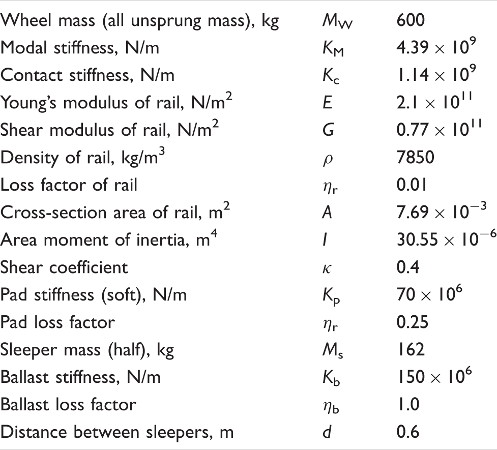
Figure 2 shows a model of track dynamics for multiple wheels on the rail. Only a single rail is considered in the model, with the connection to the second rail being ignored due to symmetry. The rail is modeled as an infinite Timoshenko beam. The lower parts under the rail represent the supports, which consist of springs, masses and springs representing the elastomeric pad, the sleepers and the ballast. The wheel is composed of a mass MW (all the unsprung mass) and a modal spring KM which represents the stiffness of high-frequency modes. The contact spring Kc between the wheel and the rail follows the Hertz law (Wu and Thompson, 2001).
Schematic view of multiple wheel-track interaction model.
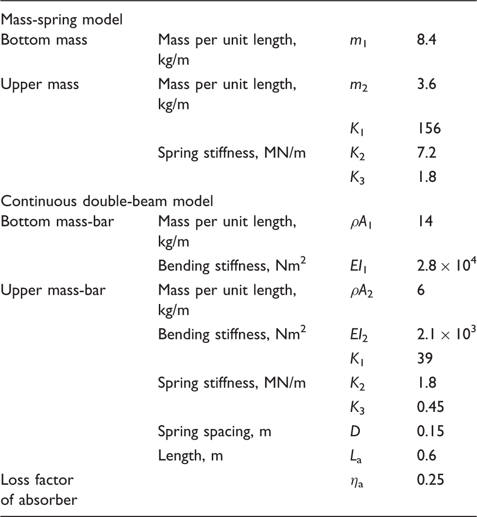
Figure 3 gives the cross-section of the two-frequency rail absorber, which consists of the steel mass-bars and the elastomeric material layers between the mass-bars and rail (Thompson et al., 2007). The rail absorbers can be devised to be either continuous or discrete (Wu, 2008; Liu et al., 2009). Based on this, the rail absorber is simplified to a damped double-beam system and a damped mass-spring system, respectively, as shown in Figure 4. The length of the continuous absorber, which is attached one by one along the rail, is 0.6 m. The discrete absorber is placed at mid-spans between sleepers. The first and second resonance frequency of the above tuned absorbers is designed to be 250 Hz and 700 Hz, respectively.
Cross-section of the rail with absorber. Different models of rail absorber: (a) mass-spring model; (b) double-beam model.

2.2. Normal contact forces between multiple wheels and the rail
The characteristics of the normal contact forces for multiple wheel–rail interactions have been studied by Wu and Thompson (2002).
When only considering a simple case of vertical interaction between a single wheel and rail, the normal contact force can be calculated by using a relative displacement excitation model

In practice, a train consists of multiple wheels on each rail and consequently multiple wheel–rail interactions occur. For a linear system the total interaction force is the sum of the active Fi and passive forces Pi, due to superposition

The active contact force Fi at each wheel can be calculated using equation (1)

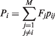
The roughness on each wheel and the rail tread are random and independent. In this paper, the roughness excitation is applied to each wheel as a sinusoidal wave with a nominal amplitude of 1 µm, but the phase of the excitation at each wheel is assumed to be evenly distributed in [−π, π].
3. Results
3.1. Parameters for the calculations
Parameters of wheel and track.
Parameters of different models of rail absorber.
3.2. Track dynamics with rail absorber
The track dynamics with rail absorber are investigated using the models in Figures 2 and 4. Calculations are carried out for a track with only four wheels on it. This is because the wave reflections or the passive interactions from other wheels that are located further away are weak due to the wave attenuation in the rail and thus can be omitted. For studying the effects of the pinned-pinned resonance, the spacing between wheels is assumed to be multiples of the sleeper span length (0.6 m), like a = 1.8 m and b = 3.6 m. For each wheel position a unit force acts at wheel 2. The results are shown in Figures 5 and 6 in terms of the point receptance and decay rate. Four cases are calculated for comparison, i.e., considering both multiple wheels and the rail absorber, corresponding to two different absorber models respectively, considering wheels only, and not considering both of the two elements.
Amplitude of point receptance and vibration decay rates. A unit force acts at the wheel 2 position and the excitation and wheels are at mid-span. Amplitude of point receptance and vibration decay rates. A unit force acts at the wheel 2 position and the excitation and wheels are at the sleeper.

From Figures 5(a) and 6(a), the point receptance at low frequencies up to about 150 Hz can be seen to be almost unaffected by the presence of the multiple wheels and the rail absorbers on the rail. At high frequencies (greater than 1200 Hz), the point receptance fluctuates around that of the rail without multiple wheels and the rail absorber on it. The reason is that the vibration of the rail with multiple wheels on it is a combination of the incident wave and the reflected waves from the wheels. At a certain location on the rail, the vibration amplitude increases where the reflected wave interferes with the incident wave constructively, or decreases where both waves interfere with each other destructively. For example, at the forcing point, as shown in Figures 5(a) and 6(a), the reflected wave may interfere with the incident wave constructively at some frequencies while destructively at some other frequencies because the wavelength of the rail vibration varies with frequency. As a result, the receptance reaches a peak at some frequencies, whilst at other frequencies it has a trough, so that the resonance fluctuates with the frequency. For track with rail absorbers, the receptances vary in all cases in the frequency range from 160–1200 Hz. The amplitude of several peaks in this frequency range is reduced and corresponding frequencies shift lower. The mass-spring and double-beam absorber models have a similar effect on the receptance. With different rail absorber models, changes in the receptances of track take place in the frequency range of 160–300 Hz and 500–1200 Hz. It can be found that the tuning frequencies of the rail absorber, 250 and 700 Hz, locates in these two frequency bands, respectively. The reason is the different types and installation positions of the rail absorber. The pinned-pinned resonance peak, at about 1050 Hz for the rail without wheels and the absorber, is found to be significantly suppressed due to the wave reflections and the rail absorber, as seen in Figure 6(a). According to Croft et al. (2009), the track system has higher corrugation rates where the rail has a strong antiresonance, as above the sleepers at the pinned-pinned frequency. When the excitation and wheels are at the sleepers for a track without rail absorbers, the pinned-pinned antiresonance in the receptance above a sleeper occurs at about 1050 Hz, as shown in Figure 6(a). The addition of rail absorbers to the track system in all cases makes the pinned-pinned antiresonance shift to a higher frequency. Compared with Croft et al.’s (2009) conclusion, this result shows an opposite trend. This is because of the different design of absorbers and wave reflections between multiple wheels.
The vibration decay rates along the track are calculated for different track models. These models include the track with and without multiple wheels and the rail absorber. Figures 5(b) and 6(b) show the decay rate to the right side of the excitation, which acts at wheel 2 and at mid-span or above a sleeper, respectively. The decay rate to the left side is almost the same. It can be seen that the vibration decay rate is high at low frequencies and low at high frequencies. At low frequencies up to about 150 Hz and high frequencies from about 1200 Hz the decay rates for the different track models are very similar. The main difference in decay rate for the different cases is between 200 and 1200 Hz. For the track with the multiple wheels and without the rail absorber the decay rate is higher than for that without the multiple wheels and the rail absorber in the frequency range of 350–850 Hz and around the first pinned-pinned resonance. The maximum difference in the decay rate between the tracks with and without multiple wheels may reach about 6 dB/m at about 600 Hz. From Figures 5(b) and 6(b) the decay rate of rail vibration can be observed to be substantially increased by using the absorber in the frequency region 600–1200 Hz. The largest difference in the decay rate between treated and untreated tracks can be seen to be about 12 dB/m at about 700 Hz.
3.3. Wheel–rail normal contact forces
In this section, the wheel–rail normal contact forces are calculated at each frequency considered by taking four wheels interacting with the rail and two different rail absorber models into account. The wheel–rail interaction forces are given in terms of the root mean square (RMS) amplitude averaged over 100 samples. Firstly, two special cases are considered: all wheels at mid-span or above the sleeper.
Figures 7 and 8 show the results for the two special cases. Only the interaction forces at wheels 1 and 2 are presented. The forces at wheels 3 and 4 are similar to those at wheels 2 and 1 respectively due to symmetry, referring to Figure 2. For comparison, the normal contact force from a single wheel–rail interaction model is also shown in these figures. From these figures the contact forces under multiple wheel–rail interactions can be seen to be greatly different from the single wheel–rail interaction, and mostly have larger amplitudes. The contact forces show two peaks at about 600 Hz and 900 Hz, respectively, as shown in Figures 7 and 8. These peaks are related to reflections from the adjacent wheels. Compared with wheel 1, the contact force at wheel 2 shows more peaks, among which the peak at about 800 Hz is high, because wheel 2 receives wave reflections from both sides. Above, three peaks of the contact forces are all suppressed due to the effect of the rail absorber. The addition of rail absorbers to the track system in all cases brings about two peaks at about 500 Hz and 1000 Hz. At low frequencies up to about 150 Hz and high frequencies from about 1200 Hz the contact forces for the different track-absorber models are very similar. The main differences in the contact force for the different models are between about 160–300 Hz and 600–1200 Hz. The double-beam absorber model introduces further relatively small peaks into the contact forces in the frequency range above 600 Hz, as shown in Figure 7. The effects of the pinned-pinned resonance on the contact forces are suppressed by the wave reflections and rail absorbers, whereas in the single wheel–rail interaction there is a peak in the contact force just above the pinned-pinned frequency (1050 Hz). There are no obvious differences between the two cases of wheels at mid-span and above the sleeper for the soft pad. According to Wu and Thompson (2002), the three main peaks in the contact forces, occurring at about 600, 800 and 900 Hz, should significantly affect rail corrugation. However, these three peaks are all suppressed and another two peaks, occurring at about 500 and 1000 Hz will affect the rail corrugation when the absorbers are applied to the track system. These peaks correspond to dips in the point receptance, as shown in Figures 5 and 6.
The root mean square amplitude of contact force averaged over 100 samples. Roughness excitation of 1 µm amplitude with random phase is applied at each wheel–rail contact position (four wheels is total) for wheels at mid-span: (a) at wheel 1 and (b) at wheel 2. The root mean square amplitude of contact force averaged over 100 samples. Roughness excitation of 1 µm amplitude with random phase is applied at each wheel–rail contact position (four wheels is total) for wheels at sleeper: (a) at wheel 1 and (b) at wheel 2.

In order to explore the practical wheel–rail interaction forces, a realistic case is calculated. In this case the distances between four wheels are chosen as a = 3.3 m and b = 6.7 m, referring to Figure 2. These parameters of the distances between four wheels are from Wu and Thompson (2002). There are two different wheel positions calculated. For case one, the first wheel is 0.25 m away from the nearest sleeper, and the second wheel is 0.05 m away from the nearest sleeper, as shown in Figure 9(a). For the second case, wheel 1 and wheel 2 interchange each other’s position.
Different positions for wheels: (a) case 1, wheel 1 0.25 m and wheel 2 0.05 m from the nearest sleeper respective; (b) case 2, wheel 1 0.05 m and wheel 2 0.25 m from the nearest sleeper respective.
Figures 10 and 11 show the results for the two different wheel positions. The interaction forces are given in terms of the RMS amplitude averaged over 100 samples. Here, only the contact forces of wheel 1 and wheel 2 are presented, since the interaction forces at wheel 3 and wheel 4 are similar to those at wheel 2 and wheel 1 respectively due to symmetry. Comparison with Figures 7 and 8 shows that more peaks occur in the frequency range of 400–1200 Hz. When the absorber is considered, these peaks are all reduced and corresponding frequencies shift lower. There are no significant differences between two different positions for wheels.
The root men square amplitude of contact force averaged over 100 samples. Roughness excitation of 1 µm amplitude with random phase is applied at each wheel–rail contact position (refer to Figure 9, case 1) for a = 3.3 m, b = 6.7 m. The root mean square amplitude of contact force averaged over 100 samples. Roughness excitation of 1 µm amplitude with random phase is applied at each wheel–rail contact position (refer to Figure 9, case 2) for a = 3.3 m, b = 6.7 m.

4. Conclusions
The effect of the rail absorber on normal wheel–rail contact forces is investigated in the frequency domain using a combined track-absorber model with multiple wheels on the rail. The wheels introduce wave reflections due to wheel–rail interactions. Such an effect has a significant influence on the point receptance and the vibration decay rate of the track and the wheel–rail contact force.
The wheel–rail contact force, which consists of an active interaction and a passive interaction, is calculated using the principle of superposition. The active interaction is generated by the irregularities on the wheel and rail treads, whereas the passive interaction is induced by rail vibration originating at other wheel–rail interaction. There are more peaks occurring in the frequency range of 500–1200 Hz due to the wave reflections between the wheels than that of a single wheel–rail interaction. However, due to the effect of the rail absorber these peaks are all suppressed and new peaks appear at other frequencies. And the amplitude of these peaks is relatively small. The effects of different absorber models on the normal wheel–rail contact forces are similar. The peaks in contact force at low frequencies get higher, whereas the peak at pinned-pinned resonance is suppressed. The predicted performances of the rail absorber on normal wheel–rail contact forces are obtained. Based on the above research work, the contact forces can be used as an input to a wear model for evaluating the effect of rail absorber on the short pitch corrugation due to multiple wheels. It is hoped that there will be investigation of the effect of the absorber parameters, different type and installation place of a rail absorber on the short pitch corrugation growth in future.
Footnotes
Funding
This research received no specific grant from any funding agency in the public, commercial, or not-for-profit sectors.