






Abstract
The direct torque control (DTC) technique of a permanent magnet synchronous motor (PMSM) has received increasing attention due to its simplicity and robust dynamic response compared with other control techniques. The classical switching table based DTC presents large flux, torque ripples and more mechanical vibrations in the motor. Several studies have been reported in the literature on classical DTC. However, the studies that actually discuss or evaluate the classical DTC are limited. This paper proposes, an alternative DTC method/switching table for PMSM, to reduce flux and torque ripples as well as mechanical vibrations. This is achieved by a simple modification in the classical DTC structure, by eliminating the two level inverter available in the classical DTC and replacing it with a three level neutral point clamped inverter. To further improve the performance of the proposed DTC, the available 27 voltage vectors are allowed to form different groups of voltage vectors such as Large - Zero, Medium - Zero and Small - Zero. Based on these groups, a new switching table is proposed. The proposed DTC is compared with the classical DTC and existing literature from the aspects of theory analysis and computer simulations. It can be observed that the proposed technique can significantly reduce the flux, torque ripples, and mechanical vibrations and improves the quality of current waveform compared with traditional and existing methods.
Keywords
1. Introduction
About 40 years ago, Blaschke (1972) proposed the concept of field oriented control (FOC) for an induction motor. Since then FOC has been dominant in the advanced AC drive market, even though it has a complicated structure. Thirteen years later, a new control technique for the torque control of an induction motor was proposed by Takahashi and Noguchi (1986) as direct torque control (DTC). Two years later Depenbrock (1988) presented another control technique, called direct self control (DSC). The first follows a circular trajectory and later follows a hexagon trajectory. Both of these have proved that it is possible to obtain good dynamic control of the torque without any sensor on the mechanical shaft. Thus, DTC and DSC can be considered as a sensorless-type control technique.
The DTC scheme is normally preferred for low and medium power applications, whereas the DSC scheme is preferred for high power applications. In this paper, the attention is focused on the DTC scheme, which is best suited for low and medium power applications. The DTC overcomes the drawbacks of FOC such as requirement of current regulators, co-ordinate transformations and PWM signal generators. DTC also provides high efficiency, high power/torque density and high reliability. Due to its simplicity, DTC allows a good torque control in a steady state and a start-up transient state.
In recent years, the DTC has been popular in a variety of electrical machines. Zhong et al. (1997) proposed the concept of DTC for PMSM. Some researchers (Caporal and Pacas, 2008) proposed this technique for synchronous reluctance machines. On the other hand, the classical DTC has some disadvantages, and listed major disadvantages are as follows:
Difficult to control torque at very low speed High current/torque ripple More mechanical vibrations
Most of the literature (Kang and Sul, 1999; Buja and Kazmierowski, 2004; Abad et al., 2008; Foo and Rahman, 2010a,b) have surveyed and analyzed classical DTC using a two level inverter and all have presented a high degree of torque ripple in the results under dynamic conditions, which will also be reflected in speed and current. This paper focuses on the possibilities for minimization of torque ripple and mechanical vibration in the DTC. The minimization of torque ripple is achieved by improvement in areas such as inverter and switching table.
In this paper, the conventional two level inverter is replaced by a three level neutral point clamped (NPC) inverter, which will have 27 voltage vectors, whereas there are only eight voltage vectors available with classical DTC. The 27 voltage vectors include large and medium voltage vectors of six numbers each, small voltage vectors of 12 numbers and three numbers of zero voltage vectors.
Some of the literature (Lee and Blaabjerg, 2007; Andreescu et al., 2008; Zhang et al., 2011b) presents a three level inverter with classical DTC, but utilizes all the 27 voltage vectors to construct the switching table. This paper proposes three kinds of DTC schemes to reduce torque ripple and mechanical vibrations. In the DTC scheme 1, only the large and zero voltage vectors are used to construct a switching table, whereas in DTC scheme 2, medium and zero voltage vectors alone are utilized to construct a switching table. Small and zero voltage vectors are considered to form a switching table for the DTC scheme 3.
Thus on the basis of the experience of the authors, the fair comparison between all the schemes are presented in both steady state and start-up transient state conditions. The comparison is useful to indicate to the users which one of the schemes can be effectively utilized for various applications that today require torque control.
2. Model of PMSM
2.1. Machine equations
The mathematical model of a PMSM can be expressed as


The electromagnetic torque developed by a PMSM in a stationary reference frame is expressed as
is Stator current vector in stationary coordinates p Number of pole pairs Rs Stator resistance Te Electromagnetic torque


2.2. Voltage vector impact on torque
According to principle of DTC, the electrical angle between stator and rotor flux vectors, δ can control the torque developed by the PMSM. In the background this can be achieved by controlling the voltage vector. Hence, the voltage vector is the prime controllable input variable in DTC. However it is mandatory to develop a relation between the torque developed and the voltage vector.
The voltage and stator flux equations in stationary frame is expressed as


From (8) and (9), we can get


From (6), the torque differentiation with respect to time t is
Us Stator voltage vector in stationary coordinates Ls Synchronous inductance ω Rotor electrical speed


It can be seen from (13) that the equation contains three components. The second component is negative and a function of speed. The third component is also negative and depends on stator resistance. The first component is always positive and depends on the voltage vector. From this it is concluded that the non-zero vector always increases the developed torque and the zero vectors always decreases the developed torque.
3. Classical DTC scheme
Based on the errors between the reference and the actual values of torque and flux, it is possible to directly control (Takahashi and Nogushi, 1986; Depenbrock, 1988) the inverter switching states in order to reduce the torque and flux errors within the prefixed band limits, which is why this technique is known as direct torque control. The block diagram of the classical DTC (Takahashi and Nogushi, 1986) for PMSM is shown in Figure 1.
Block diagram of the classical direct torque control.
The basic principle of DTC is to select stator voltage vectors according to the differences between the reference and actual torques. The reference and actual value of the stator flux is processed through a two level hysteresis comparator (Casadei et al., 2002; Buja and Kazmierkowski, 2004). If the error is positive, the magnitude of flux has to be increased and this is denoted as


The rotor reference speed is compared with the actual rotor speed and the error obtained is converted into a reference torque by using suitable proportional integral (PI) regulator (Cheng and Tesch, 2010; Tursini et al., 2010).
The reference and actual torque are processed through a three level hysteresis comparator. If the error is positive, the magnitude of torque has to be increased and this is denoted as


Finally, the most suitable voltage vectors are selected from the switching table based on the flux and torque errors for all the sectors.
4. Proposed DTC Scheme
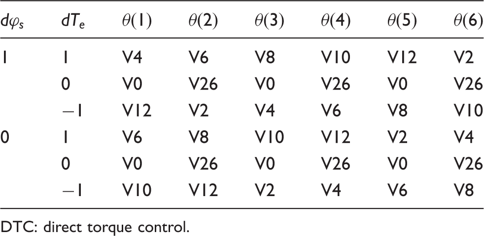
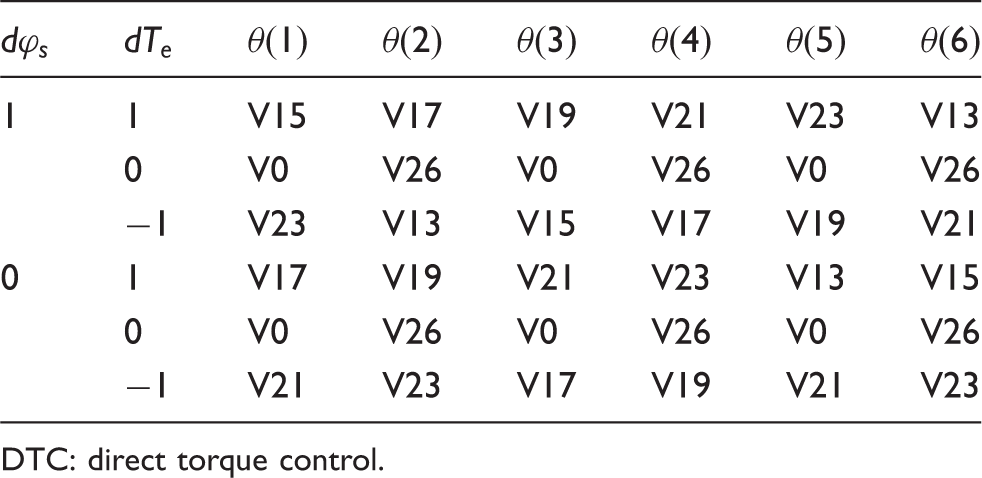
The classical DTC uses a two level inverter and produces only eight voltage vectors, which includes six non-zero vectors (V1 to V6) and the rest of them are zero vectors (V0 and V7). This does not allow smooth variation in the flux and torque. This could be one of the main reasons for large flux, torque ripples and mechanical vibrations. In this proposed DTC scheme, the two level inverter is replaced by an NPC three level inverter. Due to increment in the level of the inverter there are 27 voltage vectors (V0 to V26) available to construct the switching table, in which there are six large vectors (V1, V3, V5, V7, V9, V11), 12 small vectors (V13 to V24), three zero vectors (V0, V25, V26), and the rest are medium vectors (V2, V4, V6, V8, V10, V12). The inference from Section 3 is that the switching table plays an important role in the DTC technique. For a proper switching table the best results can be obtained. The structure of the proposed scheme is shown in Figure 2. In this proposed DTC scheme, the available 27 voltage vectors are allowed to form different groups of voltage vectors such as Large - Zero (LZ), Medium - Zero (MZ) and Small - Zero (SZ). Based on these groups, a new switching table is proposed. The proposed DTC scheme gives satisfactory results as compared to classical DTC.
Block diagram of the proposed direct torque control scheme.
Switching table for proposed DTC scheme 1.

DTC: direct torque control.
Switching table for proposed DTC scheme 2.
DTC: direct torque control.
Switching table for proposed DTC scheme 3.
DTC: direct torque control.
4.1. Proposed DTC scheme 1
The proposed DTC scheme 1 utilizes large and zero voltage vectors. In this scheme nine voltage vectors are used, in which six are large voltage vectors and three are zero voltage vectors. This scheme is almost an imitation of the classical DTC, because in both cases only large and zero voltage vectors are used. The switching table (Table 1) is constructed using these nine voltage vectors. The switching table developed in this scheme is almost similar to the classical DTC switching table. The drawback obtained in the DTC is repeated in this scheme also, because of the non-availability of intermediate voltage vectors.
4.2. Proposed DTC scheme 2
In the proposed DTC scheme 2, the medium and zero voltage vectors are used to construct a switching table (Table 2). There are six medium voltage vectors and three zero voltage vectors are available. In DTC scheme 1, the large and zero voltage vectors are used, which means the switching is between large voltage vectors and zero voltage vectors. This will produce large ripples in the flux and torque.
However, in DTC scheme 2, the medium and zero voltage vectors are used, and so the ripples in the flux and torque are considerably reduced compared to DTC scheme 1. This can be observed in Figures 7 to 11.
4.3. Proposed DTC scheme 3
The DTC scheme 2 produces slightly less torque ripples as compared to the classical DTC scheme. This is because there are no large voltage vectors used in this scheme. From the experience of previous schemes, the switching of vector plays an important role in the flux and torque ripple reduction. The switching from zero voltage to large/medium voltage increases the ripples in the flux and torque, harmonic content and stress across the switching devices.
To overcome these problems, an appropriate switching table (Table 3) is constructed using only small and zero voltage vectors. Equation (13) tells us that the large voltage vectors contributing to a torque in the same direction will lead to large errors in the actual torque. This is true for small voltage vectors also. The lesser torque ripples can be expected by combining small and zero voltage vectors. There are 12 small voltage vectors and three zero voltage vectors available in this scheme. The small voltage vectors exist in redundant pairs, i.e. six positive small vectors and six negative small vectors. So, the switching table is formed either by using positive small vectors or negative small vectors in order to balance neutral point potential.
The small voltage vectors are selected to meet the demand of the flux and torque, as well as to reduce the flux, torque ripples and mechanical vibrations. While applying zero voltage vectors, rotation of the stator flux is stopped immediately, whereas rotor flux is continuously moving in the forward direction and this reduces the angle between these two as well as torque. By applying any active voltage vector, rotation of the stator flux is continuously moving in the forward direction, which increases the angle as well as the torque. From the above discussion, it is clear that the small voltage vector reduces the torque ripple and in turn reduces the mechanical vibrations; this ensures the safe operation of the entire system.
5. Simulation and results
Quantitative comparison of the proposed DTC schemes with existing DTC schemes.

DTC: direct torque control.
Machine parameters.

5.1. Comparative study with existing work
First, the classic DTC will be carried out to show the effectiveness of the proposed DTC schemes. The proposed scheme is also compared with existing work presented by Zhang and Zhu (2011a,b) The switching table used in Figure 2 is different from the work presented by Zhang and Zhu (2011a,b).
Figures 3 and 5 present the responses at 1000 rpm with an external load of 3 Nm applied at 0.1 s for classical DTC, DTC scheme 1, DTC scheme 2 and DTC scheme 3. From the top to bottom, the waveforms are stator current, torque, flux and rotor speed, respectively. It can be seen that the current waveform is more sinusoidal in the proposed DTC schemes as compared to existing schemes. The classical DTC exhibits large flux and torque ripples. Figure 4 and Figure 6 show the harmonic analysis of stator current at 1000 rpm with 3 Nm load for classical DTC, DTC scheme 1, DTC scheme 2 and DTC scheme 3. The total harmonic distortion (THD) is calculated up to 6000 Hz.
Response of stator current, torque, flux and rotor speed at 1000 rpm with sudden load change for (a) classical direct torque control; (b) direct torque control scheme 1. Harmonic analysis of stator current for (a) classical direct torque control; (b) direct torque control scheme 1. Response of stator current, torque, flux and rotor speed at 1000 rpm with sudden load change for (a) direct torque control scheme 2; (b) direct torque control scheme 3. Harmonic analysis of stator current for (a) direct torque control scheme 2; (b) direct torque control scheme 3.


The quantitative results are carried out at 1000 rpm with 3 Nm external load for all the methods. It is seen that the stator current THD of the proposed DTC scheme 3 is 4.40%, much lower than the 5.85% and 4.67% of the existing DTC schemes available in the papers by Zhang and Zhu (2011a) and (2011b), respectively.
The average commutation frequency is calculated using the formula,
The dominant harmonics between 2000 Hz and 3000 Hz in proposed DTC scheme 3 are much less compared to other proposed schemes and the classic DTC scheme. The proposed DTC scheme 3 exhibits its better performance in terms of torque ripple, stator current THD and average commutation frequency,
Table 4 also informs us that all the proposed DTC schemes produce lesser root mean square (RMS) torque ripple as compared to the classical DTC scheme. While comparing with the existing DTC schemes of Zhang and Zhu (2011a,b), the proposed DTC scheme 3 provides lesser torque ripple. The RMS torque ripple is calculated by using equation (20).

5.2. Results at 10% of rated speed
The proposed DTC schemes are analyzed at different operating points. In Figure 7 the operating point is considered at 200 rpm (10% of the rated speed) without load as an example. Figure 7 shows the flux and torque responses for classical DTC, DTC scheme 1, DTC scheme 2 and DTC scheme 3, respectively. From left to right, the responses shown in Figure 7 are classical DTC, DTC scheme 1, DTC scheme 2 and DTC scheme 3, respectively, the flux response in the top and torque waveform in the bottom.
It is seen that at the operating point at 200 rpm, DTC scheme 1 gives almost the same performance as classical DTC because their switching pattern is almost similar. However DTC scheme 2 gives lesser torque ripple compared to classical DTC and DTC scheme 1, but gives instantaneous spikes in flux. The main drawback of the DTC drive is more torque ripple at lower speed. So this analysis provides an important conclusion; hence it can be concluded that DTC scheme 3 presents the best overall performance among the four kinds of DTC schemes including classical DTC.
5.3. Results at 25% of rated speed
At this operating point in the view of flux and torque ripple, DTC scheme 3 exhibits better performance followed by DTC scheme 2, DTC scheme 1 and classical DTC.
The flux and torque performance of DTC scheme 2 is seriously deteriorated at this 25% of the rated speed, even though the PI has been carefully adjusted. At the same time the ripples in the flux and torque waveform are also significantly diminished in the DTC scheme 3 as compared to other schemes proposed in this paper. This can be observed from Figure 8.
Steady-state response at 200 rpm (10% of the rated speed) for classical direct torque control, direct torque control scheme 1, direct torque control scheme 2 and direct torque control scheme 3. Steady-state response at 500 rpm (25% of the rated speed) for classical direct torque control, direct torque control scheme 1, direct torque control scheme 2 and direct torque control scheme 3.

5.4. Results at 50% of rated speed
Figure 9 shows the insignificant difference between DTC scheme 1 and DTC scheme 2. The high ripples and distortion in flux and torque waveforms can be seen in all the schemes. There is a torque ripple reduction in DTC scheme 3 of 70.92% compared to classical DTC, whereas 30.31%, 6.99% reduction in torque ripple in DTC scheme 2 and DTC scheme 1, respectively compared to classical DTC. At the same time, DTC scheme 3 presents only 29.08% of torque ripple in classical DTC, 31.26% of torque ripple in DTC scheme 1 and 41.73% of torque ripple in DTC scheme 2.
Steady-state response at 1000 rpm (50% of the rated speed) for classical direct torque control, direct torque control scheme 1, direct torque control scheme 2 and direct torque control scheme 3.
However, a remarkable reduction in torque ripple can be observed in DTC scheme 3.
5.5. Results at 75% of rated speed
DTC scheme 1 almost imitates the classical DTC. DTC scheme 2 presents the lower torque ripple among the other methods. According to the switching table of this scheme, at any point of time, the inverter will provide half voltages for two lines and zero voltage for one line. This voltage is not sufficient to rotate the rotor at this speed. However, DTC scheme 3 gives satisfactory operation up to 70% of the rated speed. DTC scheme 2 exhibits higher flux ripple compared to classical DTC.
5.6. Results at 100% of rated speed
It is found that there is no significant improvement in DTC scheme 1 as compared to classical DTC. Large vectors are considered in classical DTC and DTC scheme 1. According to equation (13) this will lead to large torque ripples. At the same time, DTC scheme 2 presents lesser torque ripple as compared to other schemes. Nevertheless DTC scheme 3 is not able to trace the reference target.
5.7. Start-up transient responses from standstill to rated speed
In addition to the steady-state responses, the start-up transient response and robustness against external disturbance are also carried out. Figure 13 (a)–(c) exhibits the start-up transient response without load from standstill to 100% of the rated speed for classical DTC, DTC scheme 1 and DTC scheme 2, respectively. From top to bottom, the curves shown in Figure 13 (a)–(c) are current in one phase drawn by the motor, torque, flux and rotor speed.
Steady-state response at 1500 rpm (75% of the rated speed) for classical direct torque control, direct torque control scheme 1 and direct torque control scheme 2. Steady-state response at 2000 rpm (100% of the rated speed) for classical direct torque control, direct torque control scheme 1 and direct torque control scheme 2. Comparison of the torque ripple for classical direct torque control, direct torque control scheme 1, direct torque control scheme 2 and direct torque control scheme 3. Start-up transient response from standstill to rated speed for (a) classical direct torque control; (b) direct torque control scheme 1; (c) start-up transient response from standstill to rated speed for direct torque control scheme 2.


The rising time of DTC mainly depends on the active voltage vector that is supplied by the inverter. The proposed schemes in this paper utilize one active vector (large or medium or small) and one zero vector per scheme. This is reflected in the rising time of the speed. The classical DTC and DTC scheme 1 take almost the same time to reach the rated speed. However the rising time for DTC scheme 2 is increased by 3%. DTC scheme 3 exhibits its inability to reach the rated speed and is not shown here. This is due to usage of small and zero voltage vectors in this scheme. However it should be noted that there are less ripples in the torque waveform of the proposed schemes as compared to the classic DTC scheme. Another important observation is that the starting current magnitude is high in proposed DTC scheme 2. However, this can be minimized by using pre-excitation concept proposed by Zhang et al. (2011b).
5.8. Deceleration from 1500 to 500 rpm
Figure 14 (a)–(c) presents the decelerating capabilities of the proposed DTC schemes. The change in speed responses are shown from 1500 rpm to 500 rpm. As expected, the performances in the deceleration conclude that all the proposed schemes are suitable for variable speed drives. The classical DTC scheme can still provide less ripples in the current waveform as compared to the proposed DTC scheme 1 and DTC scheme 2. Almost all the schemes take the same time to reach their steady-state value after a change in speed and there are insignificant differences among them.
(a) Deceleration from 1500 rpm to 500 rpm for classical direct torque control; (b) direct torque control scheme 1; (c) direct torque control scheme 2.
5.9. Responses to external load disturbance
The responses to the external disturbances are shown in Figure 15 (a)–(d) for classical DTC, DTC scheme 1, DTC scheme 2 and DTC scheme 3. The motor is operated at a steady state with 2.5 Nm and 50% of the rated speed, and then the load is suddenly removed in order to check the disturbance rejection capability of the proposed schemes.
Response to external load disturbance for (a) classical direct torque control; (b) direct torque control scheme 1; (c) direct torque control scheme 2; (d) direct torque control scheme 3.
In a very short period, the motor speed returns to its original speed due to its fast torque response. It is observed that about 3% peak speed increases for all the proposed DTC schemes 1, 2 and 3, whereas it is about 2.5% for the classical DTC scheme when the load is suddenly removed. However almost all the DTC schemes including the classical DTC scheme takes same time to reach its original speed after the load is removed. This comparison shows that all the proposed DTC schemes exhibit fast response of the torque as compared to classical DTC. Even though the peak speed increases about 3%, it takes less time to reach its steady state, whereas the classic DTC takes the same time to reach from its 2.5% peak speed. However the classical DTC, DTC scheme 1 and DTC scheme 2 exhibit the best performance at the cost of larger torque ripple whereas DTC scheme 3 provides lesser torque ripple and better performance in terms of disturbance rejection.
5.10. Harmonics and mechanical vibration reduction
The major disadvantages of the DTC-based PMSM drive is more torque ripple, which leads to mechanical vibrations and acoustic noise. For electric and hybrid vehicle applications the torque ripple could result in mechanical vibration and acoustic noise. These phenomena are undesirable. In this paper, the status of the total harmonic distortion in the current waveform, torque ripple and mechanical vibration have been examined and are shown in Figure 16. The RMS level of the vibration is calculated using LabVIEW software. This proves that the proposed DTC schemes are able to suppress the torque ripple and mechanical vibration.
Response of direct torque control schemes from the view of mechanical vibration. (a) Percentage total harmonic distortion of stator current; (b) root mean square level of vibration; (c) noise produced in various direct torque control schemes.
6. Important observations
In this paper the classical DTC scheme and all the proposed DTC schemes are compared in the aspects of torque ripple, start-up transient response, disturbance rejection, performance during deceleration and mechanical vibration. From the results indicated earlier, it can be seen that the torque ripple in the proposed DTC schemes is less compared with the classical DTC scheme. In most of the operating points the proposed DTC scheme 1 provides slightly higher torque ripple as compared to proposed DTC schemes 1 and 2. However, the proposed DTC scheme 3 shows better performance in terms of torque ripple as compared to the classical DTC scheme and the proposed DTC schemes 1 and 2. The use of small and zero voltage vectors in the proposed DTC scheme 3 provides better performance with the comparison of all the schemes including the classical DTC scheme. All the proposed DTC schemes present similar start-up transient response except proposed DTC scheme 3. Once again all the DTC schemes exhibit an almost similar decelerating capability, but the proposed DTC scheme 3 provides less ripple in the current waveform. All the proposed and existing DTC schemes show good disturbance rejection characteristics at the cost of higher torque ripple except the proposed DTC scheme 3. From the view of mechanical vibration, all the proposed DTC schemes provide lesser vibration as compared to classical DTC scheme.
7. Conclusion
In this paper, an alternative scheme to minimize the torque ripple for a DTC of PMSM drives has been proposed. The new switching table is proposed in which any two voltage vectors (LZ, MZ and SZ) are utilized out of four voltage vectors (L, M, S, Z) available due to increment in the level of the inverter. The performance of the proposed DTC scheme is comparatively investigated with classical DTC and existing literature. The simulation results prove that the proposed DTC schemes able to diminish the torque ripple at different operating points as compared to classical DTC. Consequently, the proposed DTC scheme also gives satisfactory performance during start-up transient and decelerating operations. The proposed DTC schemes are also capable of suppressing mechanical vibration. The settling time of the torque can be reduced if compared with the classical DTC scheme, and furthermore, the related current ripple is also reduced. The proposed DTC scheme also retains the merits of simplicity and robustness, as in DTC.
Funding
This research received no specific grant from any funding agency in the public, commercial, or not-for-profit sectors.