
Abstract
Vibration of a hollow circular plate subjected to a rotating peripheral force is analytically studied in this paper. Closed-form solutions are developed in a series form for the plate deflection as well as the distributions of the strain and stress. The Galerkin approach is adopted as the solution method and a finite element model has also been developed. Computer simulations were performed to verify the model and solution methods were adopted. Close agreement is observed when comparing the numerical results with those obtained from the analytical technique. The acoustic pressure field is eventually obtained in front of the vibrating plate surface using the Rayleigh integral method. The solution procedure presented and the numerical results obtained can be extensively utilized in the noise source separation. This has always been a significant challenge in many engineering applications such as the railway wheel-rail dynamics or that of the automotive gear trains.
Keywords
1. Introduction
Circular rotating disks are commonly employed in a wide range of engineering applications including space structures, automotive parts, and generally rotating machineries. As opposed to the vast number of studies on the free vibration of circular plates, there is only a very limited number of publications on their forced vibration. Vibrations of gears, circular saws, train wheels and turbine flywheels are a few of the applications in the forced in-plane and out-of-plane vibrations of circular plates. A detailed review on the vibration analysis of different structures including a circular plate subjected to a moving load has recently been published by Ouyang (2011). An exact closed-form solution was derived by Elishakoff and Storch (2005) for the free vibration of an axisymmetric circular plate with simply supported boundary conditions.
Kang et al. (2005) employed the Rayleigh–Ritz method to investigate the free vibration of the polar orthotropic plates. The first nine frequency parameters of the circular and the annular plates with variable thickness and combined boundary conditions were determined by Rokni Damavandi Taher et al. (2006) for different values of the aspect ratio. The three-dimensional free vibration characteristics of a thick circular plate resting on an elastic foundation, using the Ritz method, was studied by Zhou et al. (2006).
The transverse vibration and the stability analysis of a spinning circular plate having a constant thickness with different boundary conditions were studied by Bauer and Eidel (2007). A semi-analytical approach was considered by Lee et al. (2007) to determine the natural frequencies of a circular plate with multiple circular holes. The frequency response equation for the in-plane free vibration of a clamped circular plate with a uniform thickness was presented by Park (2008). The free vibrations of circular thin plates having either simply supported edges, free or clamped boundary conditions employing the differential transform method (DTM) were analyzed by Yalcin et al. (2009). An analytical formulation to describe the free vibration of a circular flexural plate with multiple circular holes, using the null field integral formulation, was developed by Lee and Chen (2010).
Ouyang et al. (2000), Cao et al. (2004) and Ouyang and Mottershead (2003) employed various numerical and experimental methods to simulate the noise and vibration of a disk-brake system by using an equivalent rotating plate object. More recently, Younesian and Esmailzadeh (2010, 2011) studied the free and the forced nonlinear vibrations of rotary blades by utilizing the multiple scales method. They have also investigated the nonlinear vibration of harmonically excited beams on viscoelastic foundations (Younesian et al. (2006, 2008, 2013).
The present study aims to provide a generalized solution procedure, based on the Galerkin method, to generate the analytical solution for the forced vibration of a circular plate traversed by any arbitrary time-varying moving external load. At the initial phase of this study, the out-of-plane mode shapes and the natural frequencies of a parametric hollow circular plate, as the fundamental solution basis, have been obtained. The generalized solution is then constructed on the basis of the orthogonality of the bending mode shapes. The analytical solution is obtained for a peripheral force rotating along the external boundary of the circular plate. The acoustic pressure field in front of the plate surface is, hence, obtained in the closed-form, and the Rayleigh integral method (RIM) is utilized for the acoustic analysis. The series of numerical simulations were then carried out and the numerical results are compared with those obtained by the finite element method. A parametric sensitivity study has been carried out to investigate the effects of different parameters, including the rotational speeds and the aspect ratios, on the transient responses.
The major contribution of this study is to present a closed-form analytical solution for the acoustic pressure field around a transversally loaded rotating disk. There is no doubt that the analytical solutions obtained would always reflect the important features of the dynamical system being considered. The closed-form solutions can provide the necessary basis for any future parametric study and sensitivity analysis. This would facilitate engineers to better select possible scenarios for the noise and vibration predictions and their control when dealing with such a rotating system. The optimal design of any passive controller either as a radial-tuned-mass-damper (RTMD) attachment, or an active control absorber system, such as a piezoelectric patch, requires reliable data. The presented finite element modeling procedure, as well as the loading profile simulation, can also be employed in similar cases for which no analytical solutions exist.
2. Mathematical modeling
The idea of a peripherally rotating load is always matched with rotating objects, which are repeatedly encountered with the surface forces at the contact patch. The surface forces in either the wheel-rail contact or the gear-tooth contact are a few examples to consider. Recently published articles (Badour, 2001; Liang et al., 2002) illustrate that neglecting the gyro stiffening and using the rotating quasi-static coordinate are two valid assumptions for frequency ratios of less than 10% (i.e., spinning frequency to the bending frequency).
When a rolling object is proceeding forward, its point of contact will move from point A to point B, as shown in Figure 1(a). In the other words, the applied force has moved from A to B along the periphery of the disk. This would indicate that the disk is held stationary and the contact force is peripherally rotating along its edge, as illustrated in Figure 1(b). This assumption is inherently valid for low angular velocities (effective for the considered examples) where the rotation does not have any significant effect on the natural frequencies and the corresponding mode shapes. The proposed innovative concept is schematically shown in Figure 1.
(a) Rotating disk with a static contact force and; (b) fixed disk with a rotating force.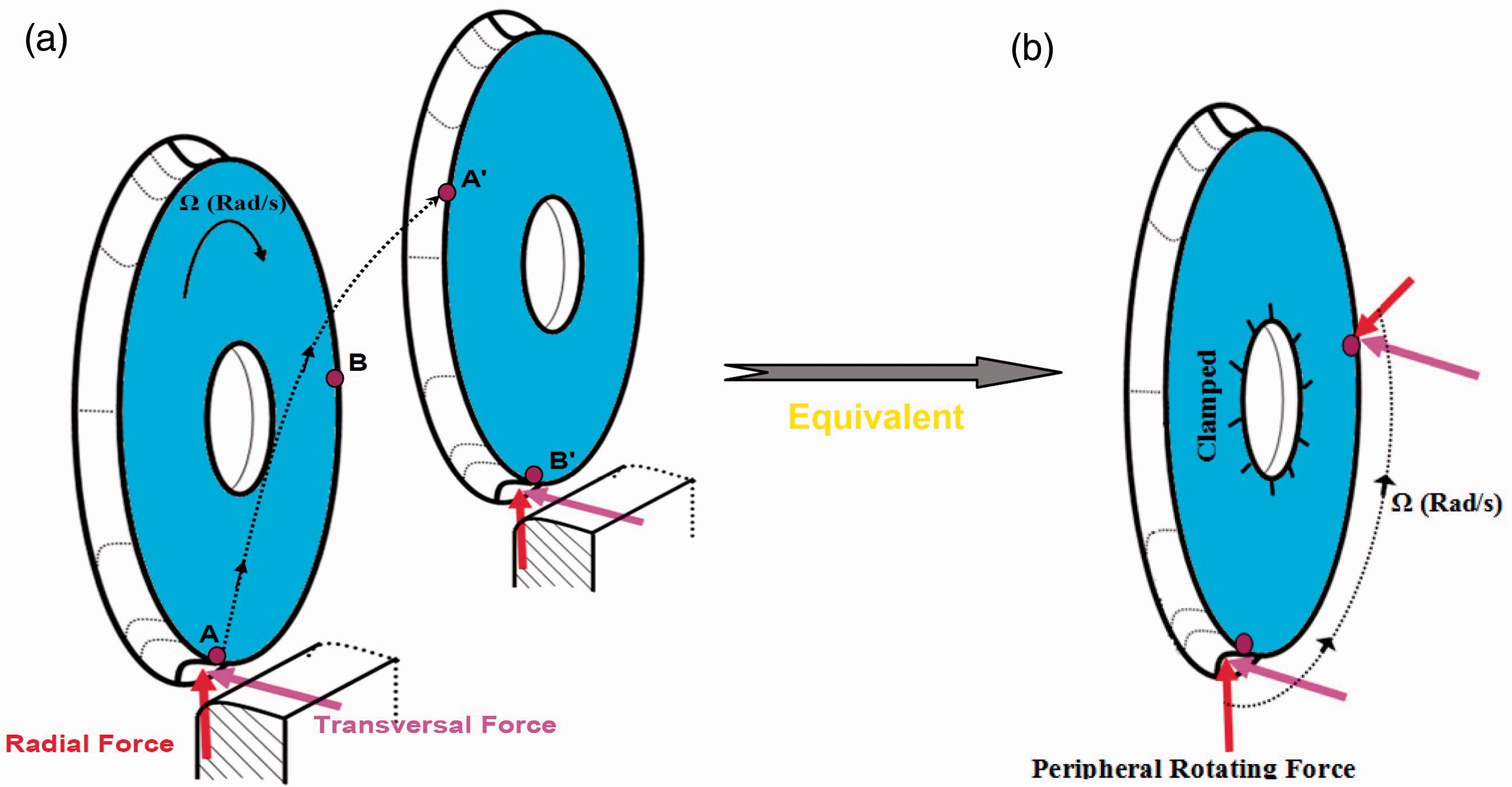
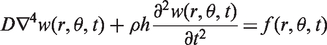
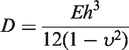
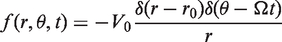
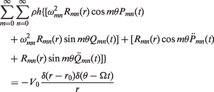
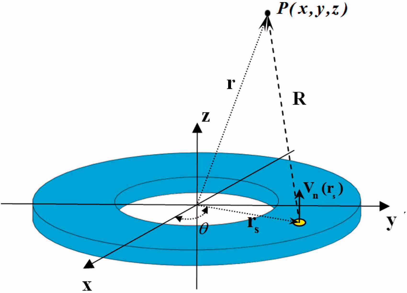
For a hallow circular disk with the applied rotating transverse load, shown schematically in Figure 2, the governing partial differential equation of motion could be expressed as (Leissa, 1969; Rao, 2005)
A circular hollow disk subjected to a rotating transverse load.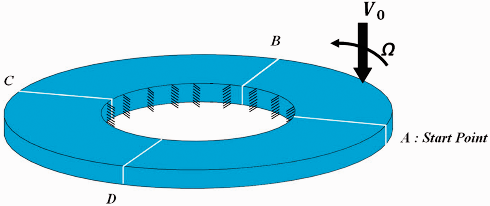
The forcing function can be described accordingly by a combination of the Dirac delta functions (δ) as
Natural frequencies and mode shapes of the case study problems.
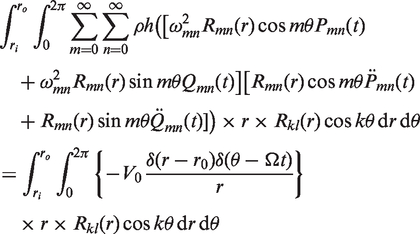
3. Analytical solution for forced vibration
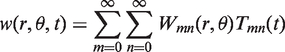
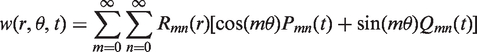
The Galerkin method is employed to obtain the solution for the forced vibration of the circular disks described in this section. According to the standard procedure of the Galerkin approach, the solution is assumed to have a general form of

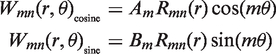
One could consider any kind of mode shape, which is represented by the summation of the sine part and the cosine part. The sine and the cosine modes are defined according to the following equations:
Accordingly, the general solution has been constructed in the form of
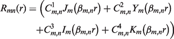
For a hollow disk, Wmn (r,θ) is proved to have a general from of (Leissa, 1969; Rao, 2005)
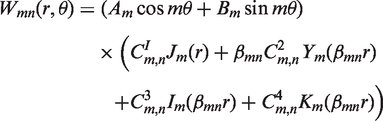
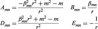
The coefficients
The zero-deflection at the inner radius will give
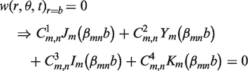
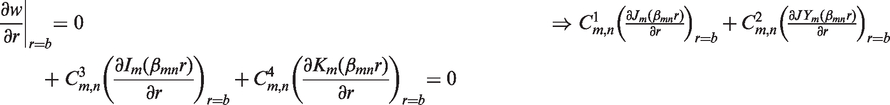
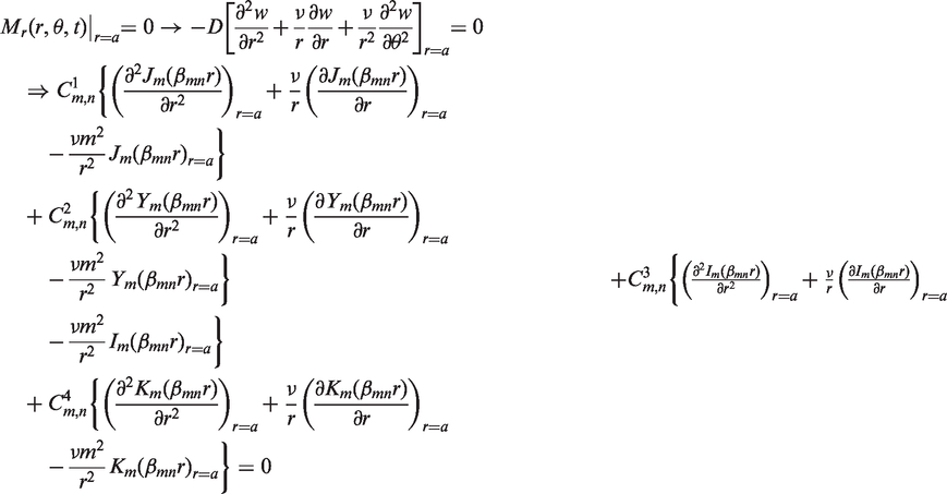
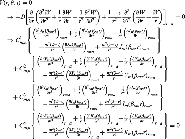
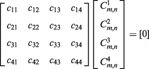
Using the above four boundary condition equations, for every value of m and n, the following eigenvalue problem would hence, be obtained:
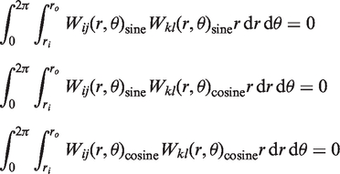
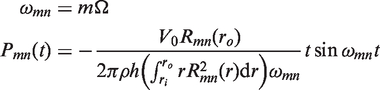
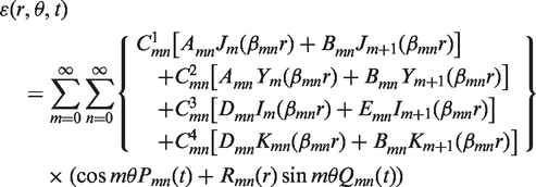
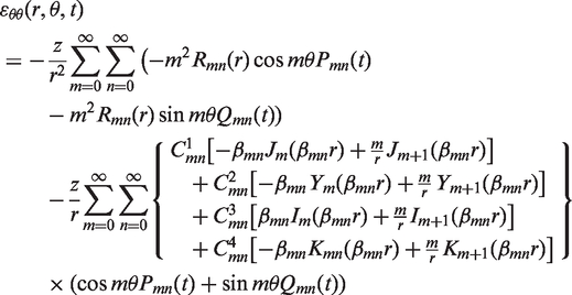
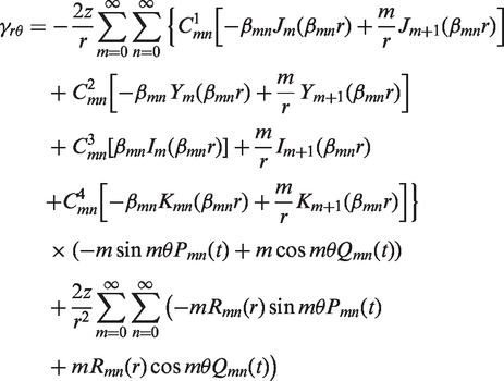
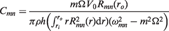
Substituting the solutions of equation (9) into equation (1), one should arrive at

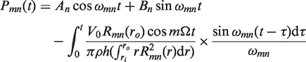
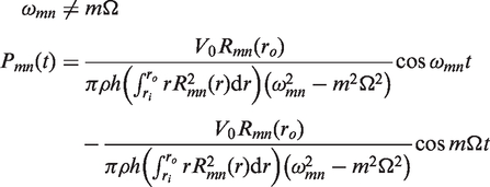
3.1. Modal coefficients for the cosine mode shapes
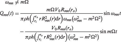
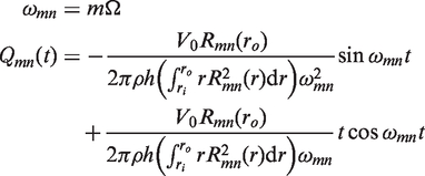
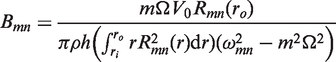
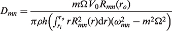
3.2. Modal coefficients for the sine mode shapes
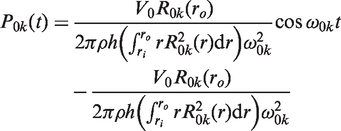
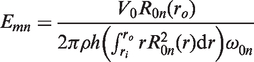
3.3. Modal coefficient for the mode shapes with zero nodal diameter
4. Acoustic pressure field
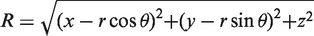
The acoustic pressure field in front of the plate surface is determined. RIM is employed for this purpose and therefore is adopted as a connecting bridge between the two topics of vibration and acoustics. The plate surface velocity is then fed into the RIM as the input profile. The acoustic pressure field at any arbitrary point 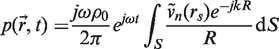
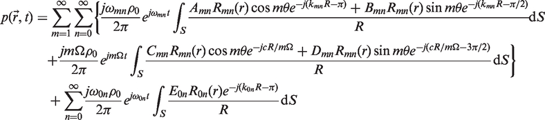
where, k
mn
= ωmn/c represents the wave number in which, c stands for the speed of the sound and is considered to be 340 m/s in this study. Different coefficients in the above equation have been defined as
Geometrical characteristic parameters employed in the Rayleigh integral method (RIM).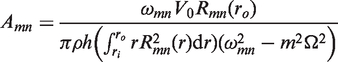
5. Numerical results
A parametric sensitivity study has been carried out in this section to investigate the effects of the variations of different parameters on the dynamic responses. A finite element model has also been utilized to compare the results for few special cases.
The varieties of plate elements have been developed by several researchers since the 1970s, in which they were extensively employed by the commercially available finite element packages such as ANSYS© and NASTRAN©. The finite element model of a circular plate with a rotating transverse load has been constructed in ANSYS©. The variations of the natural frequencies for the range of 20 Hz to 20 kHz were compared with those determined from the exact solutions, presented in the previous section, in order to validate both the analytical solution procedure as well as the finite element model. The rotating load has been simulated by the sequence of singular loads smoothly shifting from one node to the adjacent node with a defined time delay. The loadings profile, based on the prescribed scenario, is schematically depicted in Figure 4.
Loading pattern applied to the finite element model.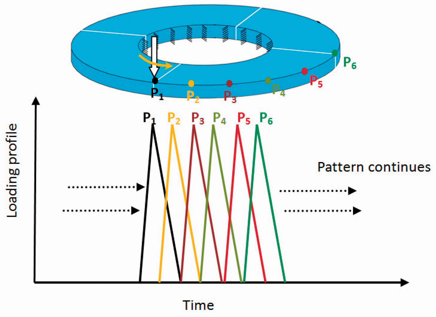
It should be noted that the time steps have been selected as 0.0001 seconds in the numerical simulations and the total number of peripheral nodes are assumed to be 200. This means that in the worst case, i.e. the rotating speed of 200 rad/s, approximately 1600 time steps are being devoted to each node. This type of slow-rate loading could approximately guarantee the continuous nature of the peripheral loadings.
In this section, a foundation has been laid for those researchers who are interested to make use of the finite element method in the vibration analysis of a circular plate when it is subjected to a moving peripheral load. The main concern is what type of element they must choose and how fine it should be. Moreover, the trend of numerical convergence is important, too. To address those concerns, the following information could be helpful to the finite element users in order to obtain similar results to those given using the series solution.
To clarify these issues, three different finite element models including the 1100, 2400 and the 4200 shell element of the type Shell-93have been chosen. This type of element will contain eight nodes with six degrees of freedom for every node. The trends of the convergence of the time responses have been illustrated in Figure 5. These presentations could provide a logical platform to decide how to design a mesh and also how fine it should be, and then the disk could be modeled in order to get reasonable results.
Convergence trend of the finite element solution (Point A, ω = 150 rad/s).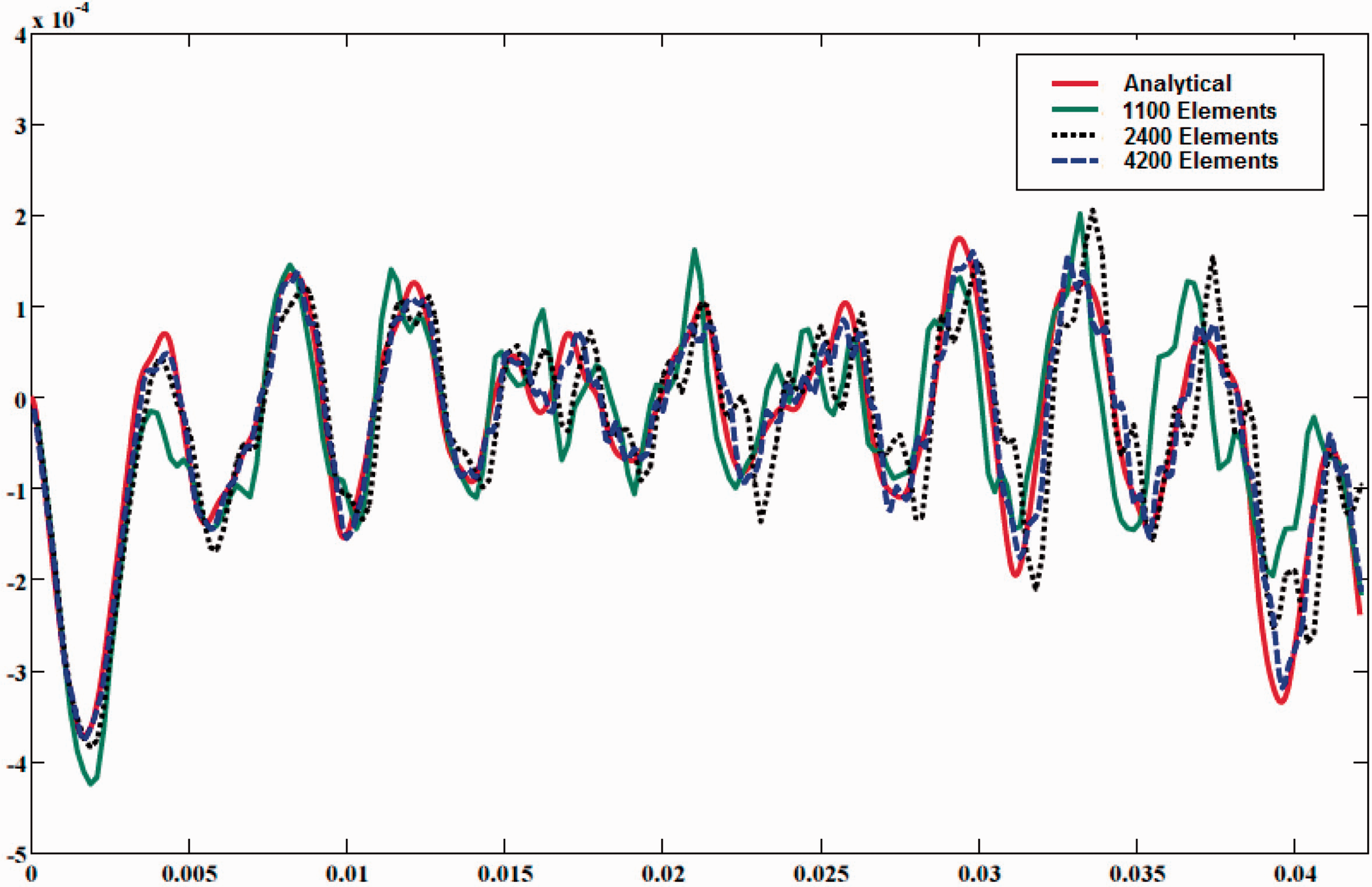
Although convergence has numerically been achieved, even with a large number of elements as shown in Figure 5, deviations in the values of the phase and amplitude were still being observed when compared with the analytical results. This variance can be the result of many factors, such as the discretization, numerical integration and the loading equalization errors. The latter could further be minimized through the evaluation of the nodal loads, reformulation of the finite element model of the rotating load, introduction of an integral formulation, or by including the potential work associated with such a rotating load in the computations.
The stability of the system has been numerically controlled and further guaranteed for all the considered cases. Table 1 shows that for the largest rotational speed of 200 rad/s, the frequency ratio (i.e., spinning frequency to the resonance frequency) is less than 0.10. Furthermore, the maximum value of the bending stress is found to be 25.2 MPa in the worst case at the position of the inner radius. This fact can guarantee that the assumption of elastic behavior is valid for all the loading cases. The time responses of the plate deflection, at a peripheral point A, are compared with those obtained using the finite element method, as shown in Figure 6.
Comparison between different solution methods (Point A, ω = 150 rad/s).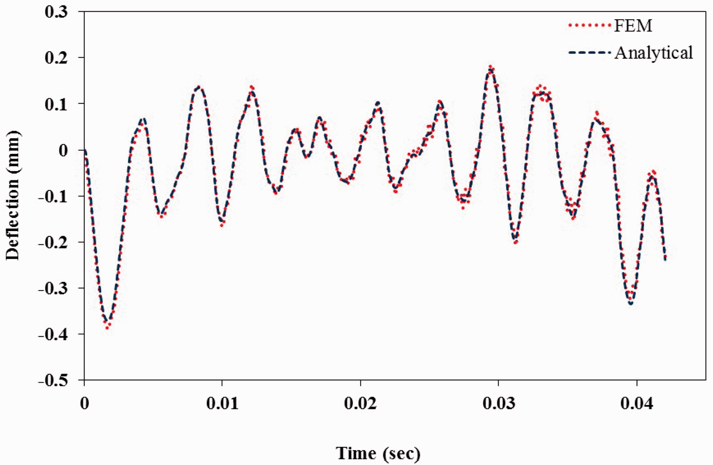
All the remaining numerical results are obtained using the analytical solutions that were addressed in the two previous sections. Figure 7(a) to (d) illustrates sequentially the time responses of the plate deflection at its peripheral points of A to D. It can be seen that the global maximums will occur with a time delay due to the travelling lag that would take place from point to point.
Time history diagram of the plate deflection: (a) point A; (b) point B; (c) point C; and (d) point D (ω = 10 rad/s).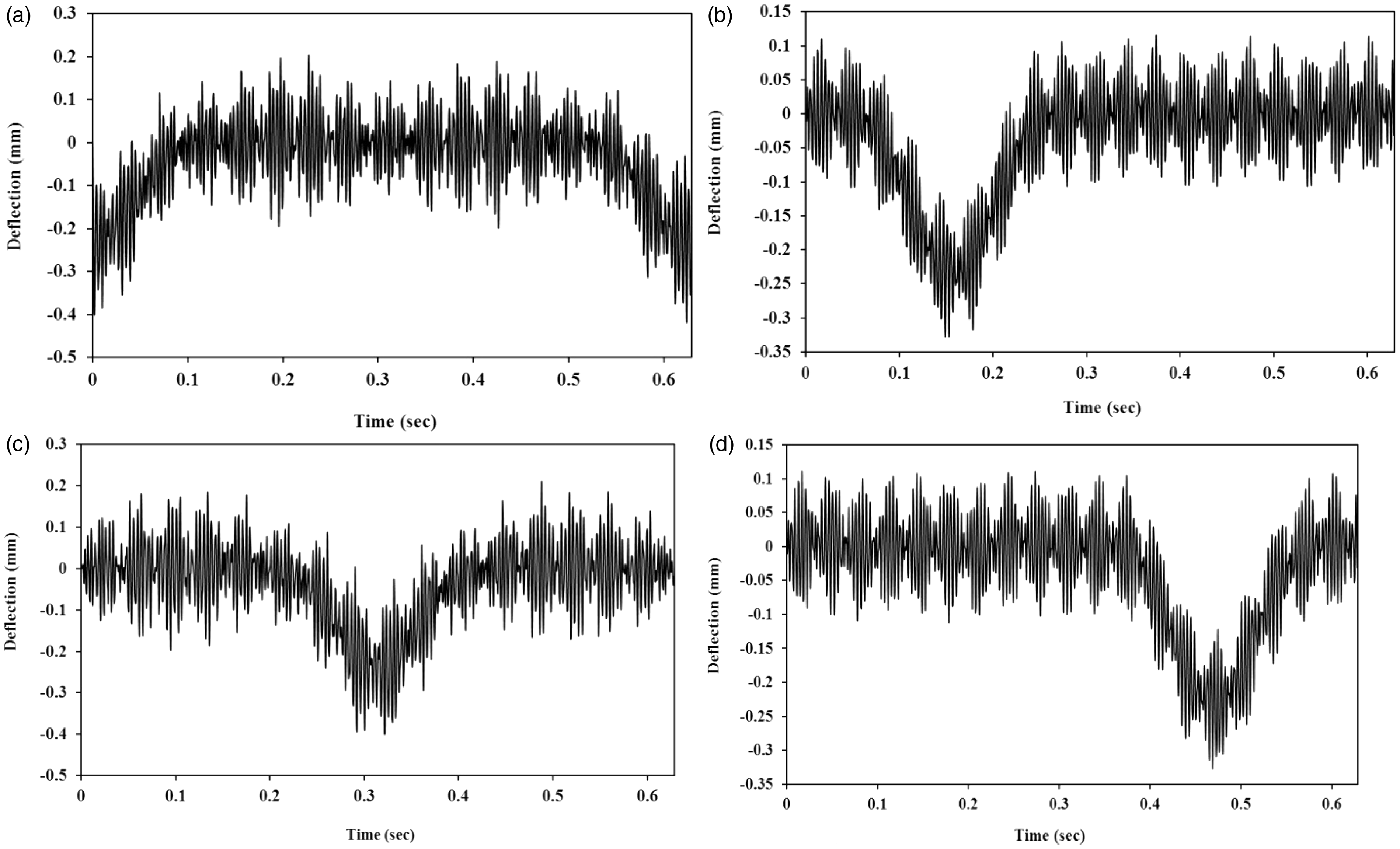
The time history diagrams of the radial stress for different rotating speeds are illustrated in Figure 8. It can be seen that the time responses for a higher frequency range are much influenced by the excitation frequency rather than the natural frequency. The acoustic pressure field in front of the plate surface has been evaluated using equation (25).
Time history diagrams of the radial stress: (a) Point C (ω = 100 rad/s); (b) point D (ω = 100 rad/s); (c) point C (ω = 200 rad/s); and (d) point D (ω = 200 rad/s).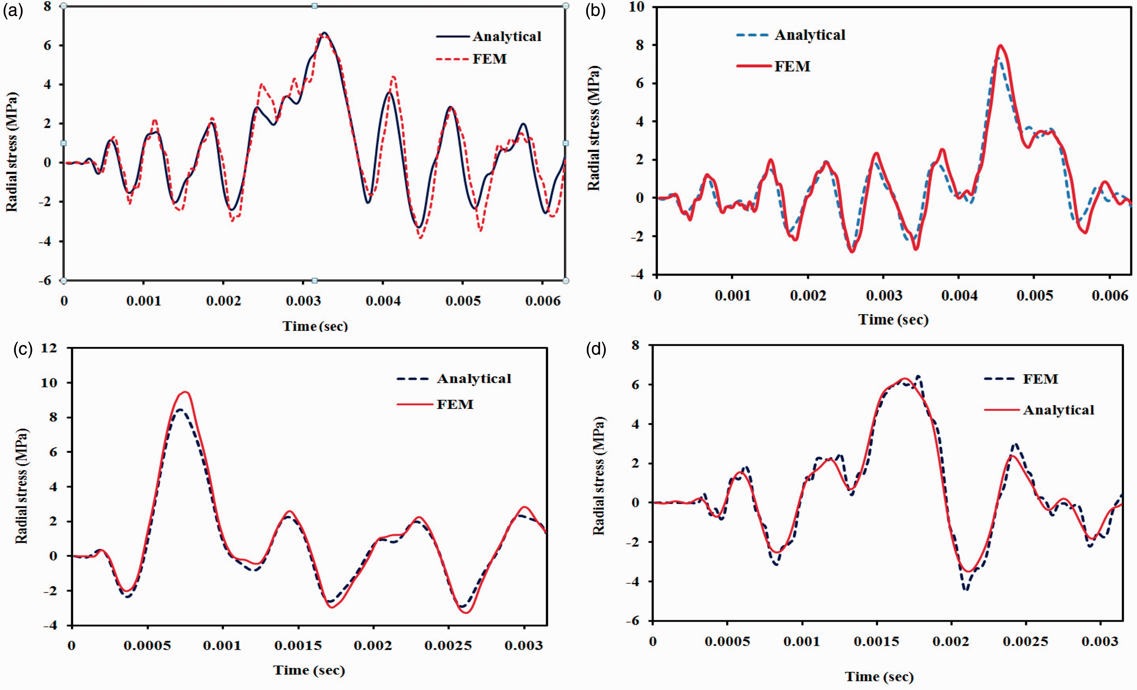
The counters at four different positions of the load (from A to D) in a single period are illustrated in Figures 9 and 10. The developed solution procedure and the numerical results obtained can be extensively utilized in the case of noise source separation (NSS). The noise source separation has always been a significant challenge in many engineering applications such as the railway wheel-rail dynamics or that of the automotive gear-trains.
Pressure field at 0.5 m in front of the plate surface (ω = 10 rad/s): (a) point B; (b) point C; (c) point D; and (d) point A. Pressure field at 0.5 m in front of the plate surface (ω = 100 rad/s): (a) point B; (b) point C; (c) point D; and (d) point A.

6. Conclusion
Analytical solutions were obtained for the forced vibration of a hollow circular plate subjected to a rotating force. A modal analysis of the system was carried out and the radial bending mode shapes were selected as the basis of the fundamental solutions. The Galerkin method was employed for the analysis and the surface deflection and the stress-strain distributions were presented in a closed-form. Another closed-form solution, using the Rayleigh integral method, has also been developed for the acoustic pressure field at the front of the plate. The solutions obtained as well as the closed-form expressions for the surface deflection, the strain and stress distributions, and the acoustic pressure field can be widely used in varieties of applications in engineering. One example is the dynamic stress analysis and fatigue design of rotating objects with an immovable contact force. The wheel-rail dynamics in railway engineering and the brake-disk interaction in automotive engineering are such examples. The solutions obtained with the developed closed-form expression could well be applied to the noise source separation in any compound systems including the rotating bodies. Furthermore, another important application of the developed methodology and the results presented in this study is the structural noise absorption in rotating objects with contact forces. Finally, in the vibration suppression of rotating objects with contact forces one could utilize the presented analysis in order to find the optimized tuned-mass-dampers.
Footnotes
Funding
This research received no specific grant from any funding agency in the public, commercial, or not-for-profit sectors.