
Abstract
The disturbance propagation and active vibration control in complex space truss structures are investigated. Firstly, based on the advanced Timoshenko theory, the accurate dynamic responses of the space truss are obtained by the traveling wave method. Each structural member is treated as a waveguide, which transmits longitudinal, bending and torsional waves, and is connected by the junction. Secondly, the active power flow transmission of the space truss is suppressed by the feedforward active vibration control. Finally, the numerical simulation is implemented. The simulation results indicate that the dynamic responses of a space truss structure calculated by the traveling wave method are accurate and reliable in comparison with the results obtained by the finite element method. The dynamic responses are more accurate when using the Timoshenko beam model due to considering the effects of rotary inertia and shear distortion, especially in medium and high frequency ranges. Active control effects, attained by minimizing the active power flow, are compared with those achieved by minimizing the acceleration for suppressing the active power flow or the acceleration. It shows that active control effects achieved by minimizing the active power flow are much more effective than those reached by minimizing the acceleration, whether the error sensor is located in the far field or near field of the control source. In addition, the small error of the optimal control force has slight effects on the control results.
Keywords
1. Introduction
Space truss is one of the most common structures used in aerospace and building engineering. As the development of aerospace technology, a space truss will be used as the main support structure of large spacecraft in the future. Disturbance produced by various external excitations, such as a reaction wheel, can propagate through the space truss structure and induce the vibration of the whole structure. The vibration will exist for a long time because of the small damping in a space environment, which will influence the working performance of high-precision sensitive equipment (Miller et al., 2007; Blaurock et al., 2008; Liu et al., 2008). So it is necessary to investigate the disturbance propagation and the vibration suppression of space truss structures.
The power flow model can be used to describe the vibration propagation in the structures. The active power represents the time-average power in a vibration cycle and it corresponds to the local net transport of disturbance energy. The analysis of power flow in a vibrating structure has been recognized as an important tool for vibration control. At relatively low frequencies, the finite element method (FEM) is suitable for the evaluation of power flow in vibrating structures. However, in the medium and high frequency ranges, FEM is ineffective because of the requirement that the mesh needs to be very fine, which makes model generation difficult and the computational costs relatively high. Additionally, because of increasing uncertainty of various parameters in structural models at high frequencies, the confidence of results obtained by the traditional method decreases. Statistical energy analysis (SEA) is developed to overcome the weaknesses of the traditional vibration methods at high frequency ranges. Statistical energy analysis predicts modal- and frequency-average vibration behavior of a structure and uses energy as a primary variable. However, SEA is only well suited for high frequency analysis of structures with high modal density, and cannot predict the spatial variation of energy in a subsystem. The traveling wave method (TWM) (Von Flotow, 1986) from the point of fundamental vibration explains the nature of the vibration propagation and can give the fundamental law of vibration propagation in the structure. In general, there is no modal restriction in the TWM and the method is more robust. Therefore, a wave description can be used to establish the dynamics model and predict the power flow of the structures.
The fundamental concepts of power flow analysis were firstly discussed and described by Goyder and White (1980a,b,c). They used the rate of energy flow to characterize the dynamic response of vibrating systems. Cuschieri (1990, 1992), and Cuschieri and McCollum (1990, 1996) studied the power flow of two-dimensional plate-like coupled structures with a mobility power flow approach and analyzed the effect of changes in parameters on power flow characteristics of the structures. They further described the flexural behavior of an L-shaped plate structure consisting of thick plates with rotary inertia and shear deformation effects. Xiong et al. (2001) developed a generalized mobility/impedance power flow mathematical model to analyze the dynamical behavior of a complex coupled system. Choi et al. (2009) presented an equivalent mobility-based power flow progressive method to determine power flow for a sandwich configured floating raft vibration isolation system based on a higher-order sandwich theory.
Miller and Von Flotow (1989) used wave mode amplitudes as the basic unknowns from a wave scattering analysis to extract the power flow in simple structural networks. Beale and Accorsi (1995) presented a general matrix method for the analysis of power flow in two- and three-dimensional frames using a wave scattering approach. In their researches, axial, torsional, and flexural waves were considered, and shear deformation and rotatory inertia were included in the flexural waves for medium and high frequency analysis.
Park et al. (2001, 2003) and Park and Hong (2008) derived energy equations to examine the propagation of longitudinal waves and in-plane shear waves in finite coupled thin plates, and developed an approximate power flow model for the analysis of the flexural waves in finite orthotropic plate transversely vibrating in the medium and high frequency ranges. On this basis they presented power flow models to analyze transversely vibrating finite Mindlin plate, considering the effects of shear distortion and rotatory inertia, which are very important at high frequencies.
Romano et al. (1990) dealt with a formulation of the Poynting vector (structural intensity) for thin, elastic shells and plates. Xu and Zhang (2000) investigated the characteristics of vibrational power flow in an infinite elastic circular cylindrical shell filled with fluid. Wang et al. (2002, 2004) formulated a substructure approach to investigate the power flow characteristics of an L-shaped plate and a complex plate-cylindrical shell system. Seo et al. (2003) developed a power flow analysis to predict the vibrational responses of a reinforced beam-plate coupled structure in frequencies ranging from medium to high. Zhu et al. (2006) studied the structural power flow characteristics of an infinite cracked Timoshenko beam. Xie et al. (2007) developed a fully rigid-elastic-coupled dynamic model for a vibration isolation system and investigated the vibrational power transmission behavior of the system. Yan et al. (2007, 2008) presented the vibrational power flow in a submerged infinite unconstrained viscoelastic cylindrical shell using a wave propagation approach. Furthermore, they analyzed the input power flow from a cosine harmonic line force into a submerged infinite cylindrical shell with doubly periodic supports.
Active vibration control has been used extensively to suppress the active power flow in simple beams and plates. Many researchers have studied the active control of power flow for beam structures. Fuller and Gonidou (1988) and Gibbs and Fuller (1992) studied analytically active control of flexural power flow in infinite and semi-infinite thin elastic beams, and an experiment for the active control of flexural power flow was made to verify the control method. Miller et al. (1990) studied the control of power flow by modifying junction reflection and transmission properties. Pan and Hansen (1991) derived the power flow expressions of the bending, torsional and longitudinal waves, and analyzed the active control of total power in infinite beams. Elliott and Billet (1993) investigated broadband active control of flexural waves propagating along a beam theoretically and experimentally. Svensson et al. (2008) investigated the effect of material parameters and cross-sectional dimensions on active scattering control of flexural waves at beam junctions.
Schwenk et al. (1994) studied the filtered-x least-mean-squares algorithm to control adaptively the structural vibration intensity in an infinite beam. A number of control actuator/error sensor configurations were used to investigate the effectiveness of the control method. The results showed the effect by controlling the intensity was better than that by controlling the acceleration when the error sensors were in the near field. Pereira et al. (1998) used a frequency-domain adaptive structural intensity control method by minimizing the active part of the structural intensity to reduce the overall vibration level in the beams. The basic idea behind this strategy was that the control forces dissipated the input power due to the perturbing forces, thus preventing the structure from having to vibrate in order to dissipate the incoming energy. Audrain et al. (2000) studied the instantaneous structural intensity control in finite beams based on theory and experiment. A comparison was made between classical acceleration control and structural intensity control. The results confirmed that using intensity control allowed the error sensors to be placed closer to the control source and the primary disturbance. Liu et al. (2010a) studied the power flow transmission and active vibration control of a finite L-shaped beam by the traveling wave method. In their papers, the near field effect of the error sensors and the small error of the control forces on the control results were considered. The results indicated the effect of the active control attained by controlling the power flow was, in some cases, much better than that achieved by controlling the acceleration.
The active control of power flow in plate structures has been investigated by several researchers. Pan and Hansen (1993, 1995) investigated the feedforward active control of the harmonic vibratory power transmission along a semi-infinite plate and analyzed the effect of control force number, error sensor type and location on the power transmission control effort. Kessissoglou (2004) and Keir et al. (2005) investigated power flow propagation in L-shaped plates in both the low and high frequency range, and an exact solution was derived to describe the flexural, in-plane longitudinal and in-plane shear wave motion in the plates. Then they presented the feedforward active control of the dynamic response characteristics for a series of rectangular coupled plates. The results demonstrated that global attenuation may be achieved using a single control source and a single error sensor for L, T and cross shaped plates. Liu et al. (2010b) studied the vibration propagation and active control of power flow in a finite connected plate structure. The control effects by the feedforward active power flow control were compared with those by the optimal acceleration control, and the effects of the small error of the optimal control force on the control results were analyzed.
Although there has been much work on analysis and the active control of power flow transmission for infinite, semi-infinite, finite simple beam-like, plate-like and shell-like structures, there has been less focus on the active control of power flow transmission for complex space truss structures. And previous works on the transmission analysis and active control of power flow in beams are mainly based on the classical Euler-Bernoulli beam theory, which is not suitable for medium and high frequency analysis.
In this paper, the power flow transmission and active vibration control in complex space truss structure are investigated. Considering the effects of shear distortion and rotatory inertia, accurate dynamic responses of the space truss structure are obtained with TWM and the results from TWM are compared with those from a conventional FEM. Then the active power flow through the space truss structure based on the Timoshenko theory is calculated and the results are analyzed and compared with the Euler-Bernoulli theory. Finally, the active control based on the structural active power flow is used to suppress the vibration of the whole space truss structure, in which the influence of the errors of the control force and locations of error sensor on the control results is considered. It indicates that the active power flow transmitted through the space truss structure can be effectively suppressed by the active control method.
2. Traveling wave dynamics of space truss structure
The space truss structure is composed of one-dimensional waveguides (structural members) interconnected at junctions (boundaries). Each structural member is treated as a waveguide, which transmits longitudinal, bending and torsional waves. The member dynamic models are described by the wave equations. Wave type conversion will occur among longitudinal, bending and torsional waves at the junctions. All external forces and displacement boundary conditions are applied to the junctions. In order to obtain more accurate dynamic characteristics of a space truss in the medium and high frequency ranges, the Timoshenko beam theory, including the effects of shear deformation and rotatory inertia, is used to analyze the bending wave motion of the member.
2.1. The model of member
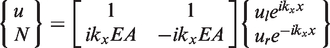
The harmonic vibration equation of longitudinal motion in the absence of external force is
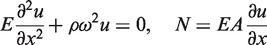
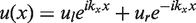
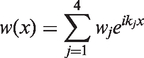
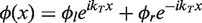
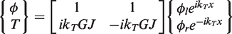
The longitudinal displacement of the beam can be given with the traveling wave method (Beale and Accorsi, 1995)
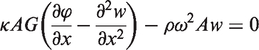
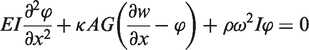
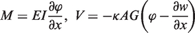
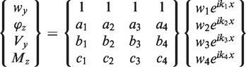
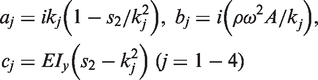
Based on the traveling wave method, the transverse displacement and cross-sectional rotation for the flexural wave are expressed as (Beale and Accorsi, 1995)
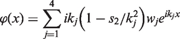
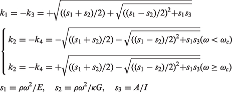
The waveguide equations of a flexural wave for the Timoshenko beam in the y-axis direction are written in equation (10), and the waveguide equations of a flexural wave in the z-axis direction are similar.
The governing equation for harmonic torsional vibration in the absence of external force is expressed as
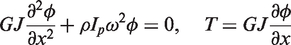
The angle of twist for torsional wave can be written with traveling wave method (Beale and Accorsi, 1995)
For the three-dimension space truss structure, the waveguide equations contain longitudinal, flexural and torsional waves. Using equations (4), (10) and (14), the waveguide equations of the member are as following

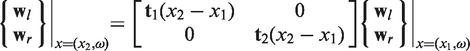
The transmission equations which relate to the traveling wave vector at different positions along the member length are expressed as
2.2. The model of junction scattering
The external forces and displacement boundary conditions are applied to the junctions. Continuity of member displacements, equilibrium of member forces and displacement boundary conditions at the junction must be satisfied.
Assuming a junction connected to N members, there are incident wave
The left end of a member is connected to the junction. For the case,


The conditions that must be satisfied at a junction or boundary are written in the following general form:
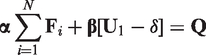

The general junction scattering equations are obtained by relating the outgoing wave to the incident wave. Substituting equation (17) or (18) into equations (19) and (20) yields

2.3. System equation of space truss structure
For the mth member, the outgoing and incident wave vector of the member are defined as
Like the superposition of the stiffness matrix and mass matrix in the FEM, the system scattering equations are written by assembling all junction scattering equations (21)

The system transmission equations are given from equation (16)

From equations (22) and (23), the following equations can be obtained

3. Active control of power flow
Vibratory power flow is a desirable cost function for active vibration control because it provides a true measure of the energy transmitted into a structure. Therefore the minimization vibrational power flow will ensure a reduction in vibration levels throughout the structure. The power flow is equal to the product of the deflection velocity and collocated force, therefore, only by reducing the transmitted force or velocity amplitude, but neglecting the relative phase angle, will not necessarily be successful in achieving global structural vibration reduction.
The feedforward active control approach which has been used to control the power flow transmitted in the beams (Schwenk et al., 1994; Pereira et al., 1998; Audrain et al., 2000; Liu et al., 2010) and plates (Pan and Hansen, 1995; Kessissoglou, 2004; Keir et al., 2005; Liu et al., 2010) is also used in this paper. The active power flow of a space truss structure is used as the cost function, and a feedforward, adaptive algorithm can implement the suppression of vibratory power transmission through the structure.
The active power flow represents time-average energy transmission through the structure, and the active power flow at the position x in the member for the space truss structure is given by Beale and Accorsi (1995) and Liu et al. (2010a,b)

The displacement and force vectors at an arbitrary position of the space truss structure generated by the disturbance source F0eiwt acting at the position x0 are given by


When the space truss structure is driven simultaneously by the disturbance force F0eiwt and the active control force Fseiwt, the total displacement and force vectors at the arbitrary position x are given from equations (26) and (27)


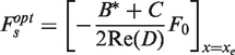
Substitute equation (30) into (29), the minimizing active power flow transmission through the position x of the space truss structure can be obtained. In conclusion, the active power flow is used as the objective function, and the optimized control force amplitude and phase are acquired by optimization, which is applied to the structure. A feedforward active control algorithm is used to realize the active control of power flow transmission. Then the whole vibration of the space truss structure is suppressed.
4. Numerical simulations and discussions
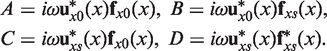
In the presented work, the two-bar space truss structure as shown in Figure 1 is studied. The truss structure consists of 16 straight beam members, 10 diagonal beam members and 12 junctions. The cross-section of beam is circular and the diameter is R = 0.02 m. The length of straight beam and diagonal beam are Ls = 1 m and Ld =
The schematic diagram of space truss structure.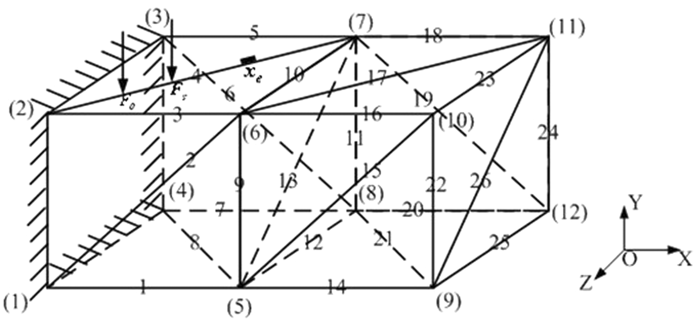
The numerical simulation and analysis are made. Firstly, the displacement responses subjected to harmonic excitation are calculated by TWM and the results are compared with those by FEM to verify the correctness and validity of the proposed method. Then, in comparison with the Euler-Bernoulli theory, more accurate active power flow is obtained in the medium and high frequency ranges based on the Timoshenko theory. Finally, the power flow is used as the cost function, and the feedforward control algorithm is implemented to suppress the vibration of the space truss. The results based on active power flow control are compared with those achieved by acceleration control. In addition, the influence of both the errors of the control force and locations of error sensor on the control results is considered.
4.1. Dynamic response results analysis
Figure 2 shows the displacement response at the mid-point of beam 25 in the y-axis direction calculated by FEM and the proposed TWM. In the FEM, 520 elements and 400 order modals are chosen to calculate the displacement response.
Comparison of responses with travelling wave method and finite element method, (a) Low frequency, and (b) medium and high frequency, (travelling wave method: TWM; finite element method: FEM).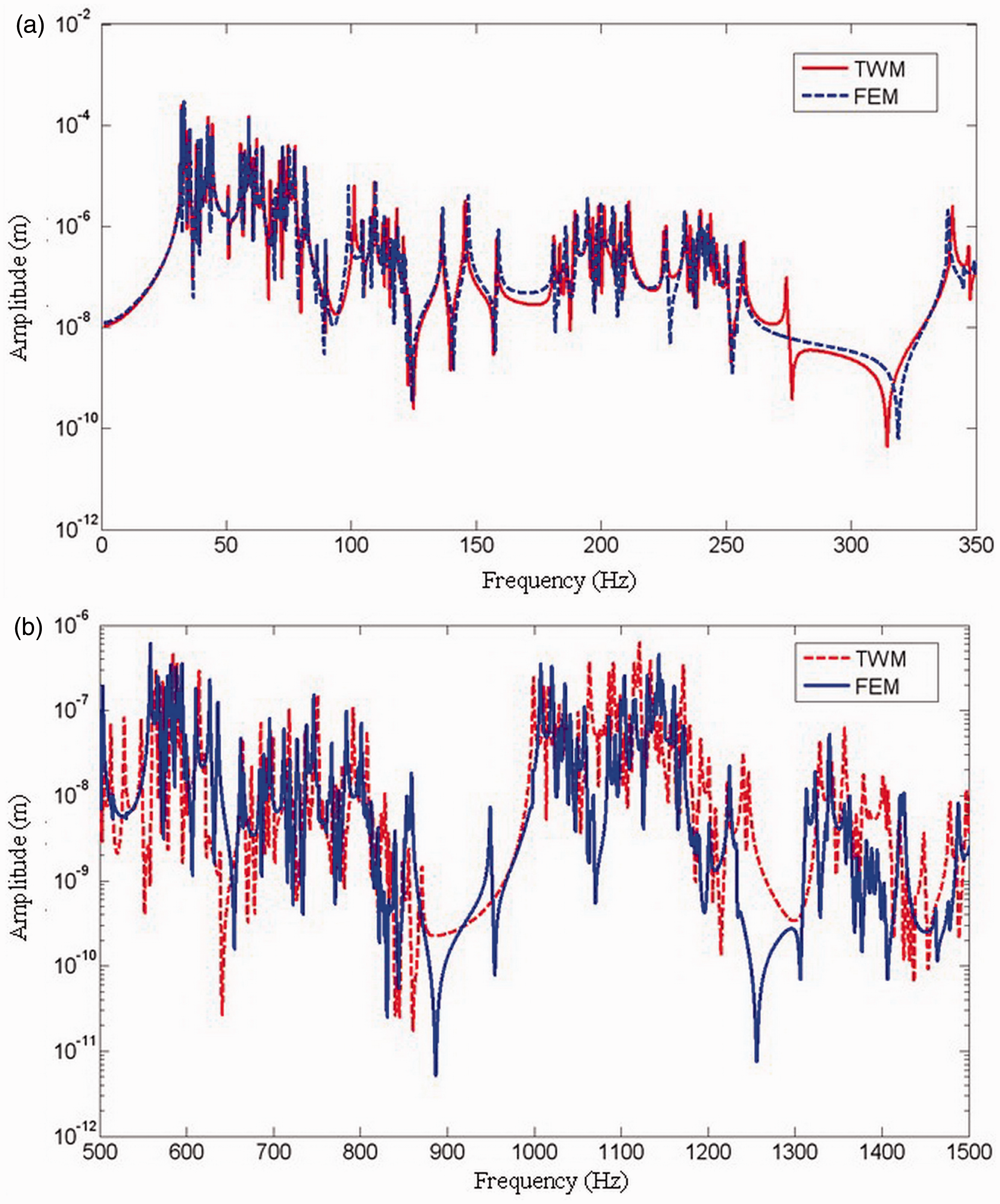
The TWM results agree well with the results of the FEM in the low frequency regions in the space truss structure as shown in Figure 2. However, the results are different between TWM and FEM in the medium and high frequency regions. The reasons are that FEM generally uses the modal superposition method to calculate the response of the structure and the results are accurate for the low frequency. But the error of the results for FEM becomes larger as the frequency increases because of the uncertainty and the truncation error of the high-order modes. So the results of the FEM are not precise for the medium and high frequencies. But the response in the medium and high frequency regions that satisfy the wave model assumption can be calculated by TWM for there is no modal restriction in the method. Therefore, the dynamic response of the structure can be accurately calculated by TWM, especially in the medium and high frequency regions. In addition, the space truss structure is divided into 520 beam elements in the FEM while there are only 26 beam members in the TWM. So FEM requires more computational effort than TWM to achieve the same accuracy.
In Figure 3, the active power flow at the mid-point of beam 25 for the space truss structure is calculated based on the Timoshenko beam theory, and the results are compared with those obtained by the classical Euler-Bernoulli beam theory.
Comparison of active power flow with Timoshenko theory and Euler-Bernoulli theory. (a) Low frequency, and (b) medium and high frequency, (dB ref: 10-10w).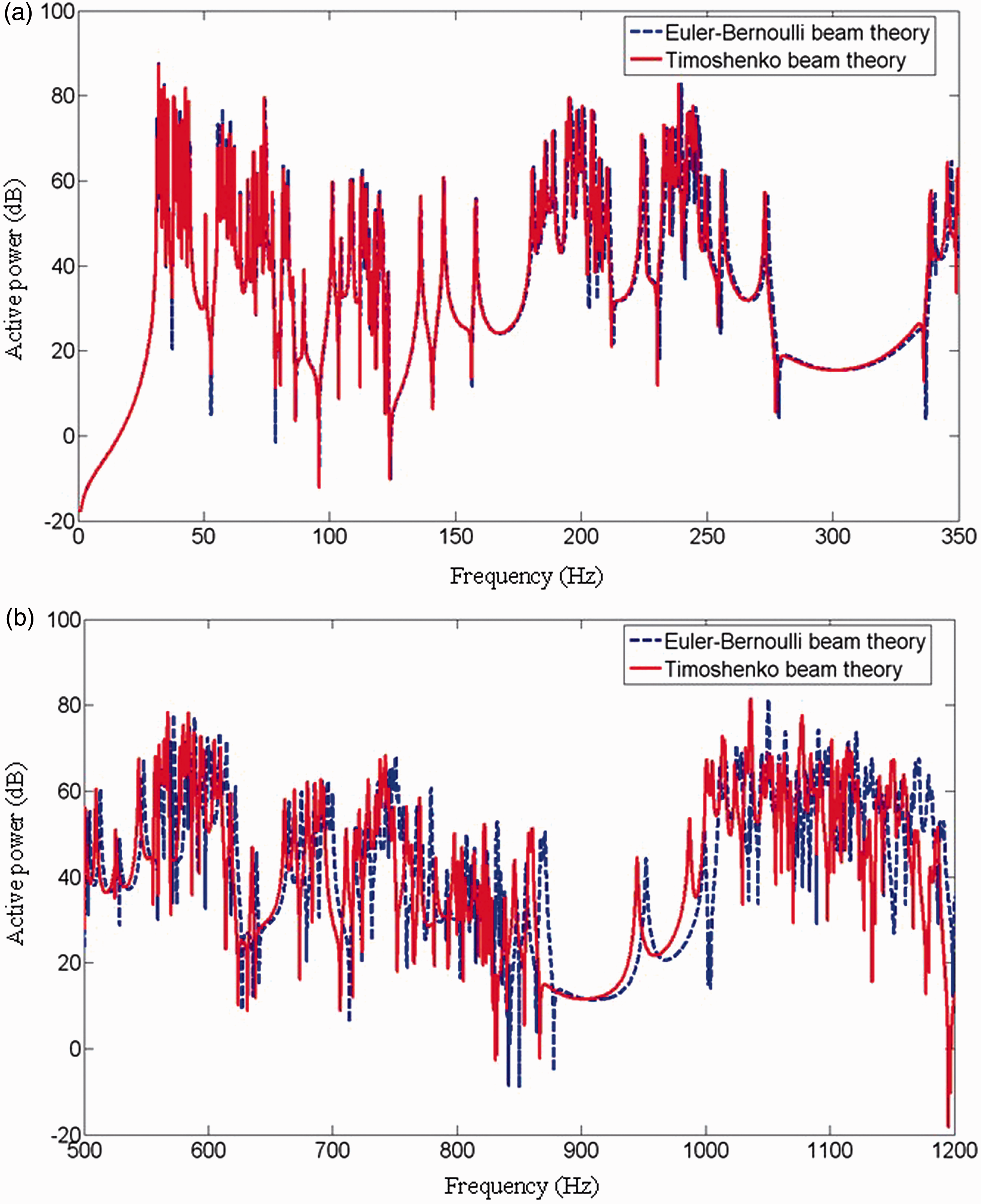
At low frequencies, the results of the active power flow with two kinds of theory are almost similar from Figure 3. However, the results are obvious deviations between the Timoshenko theory and the classical Euler-Bernoulli theory as the frequency increases. The resonance frequencies obtained by the Timoshenko theory are significantly lower than those obtained by the classical Euler-Bernoulli theory. In the classical Euler-Bernoulli theory, the influences of shear deformation and rotatory inertia are ignored and shear stiffness of the beam is considered to be infinity, but the actual shear stiffness is finite. Therefore, the power flow transmission of the space truss structure is influenced by shear deformation and rotatory inertia based on the Timoshenko theory, and the resonance frequencies are lower than the results calculated by the classical Euler-Bernoulli theory. In conclusion, the Timoshenko beam model is more accurate for dynamic analysis of the space truss structure due to its more complete representation of beam behavior, especially in the medium and high frequency ranges. Additionally, the results are closer to practical engineering.
4.2. Active control of power flow
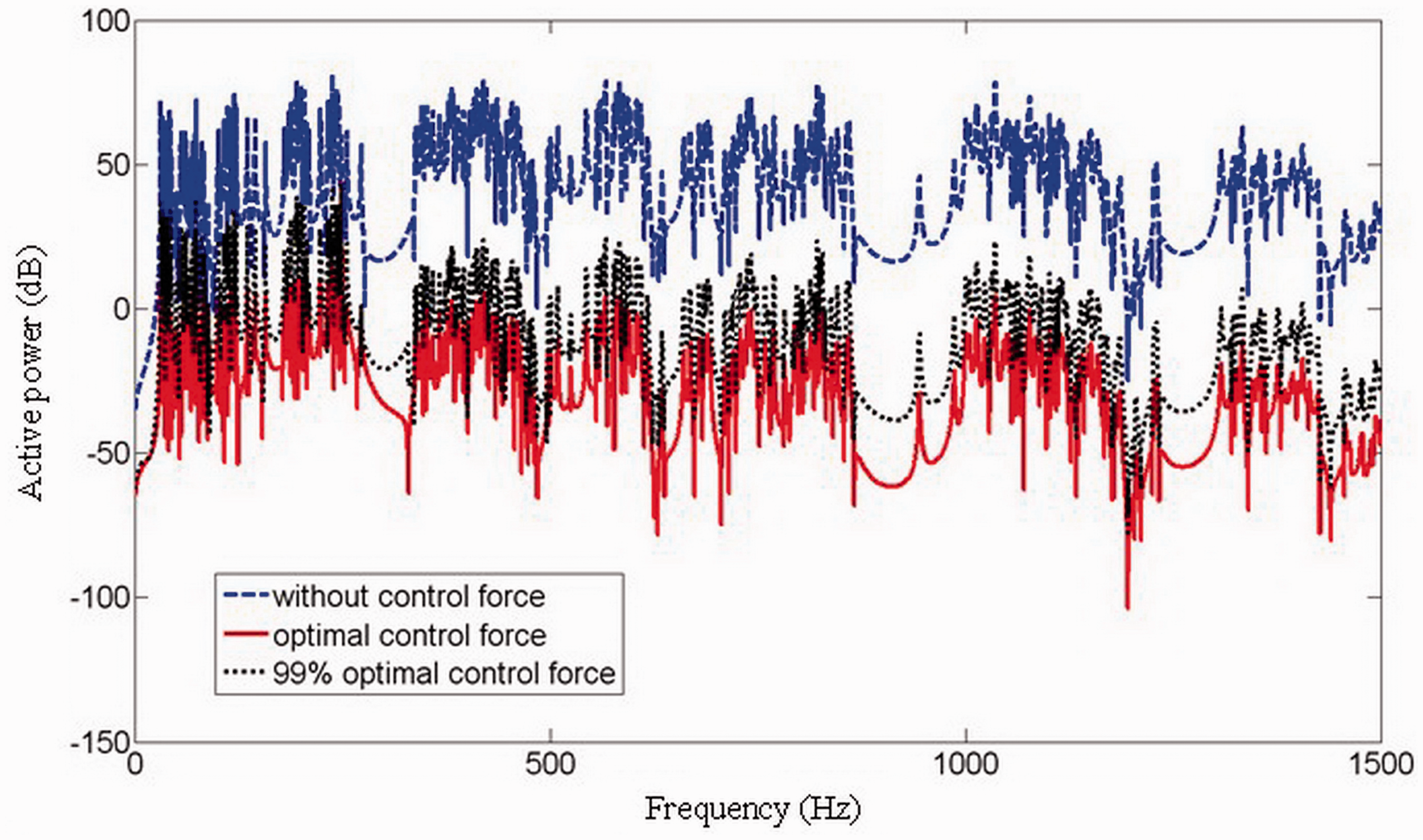
In Figure 4, the active control with different control forces is used to suppress the active power flow at the mid-point of beam 25, where the error sensor is located at x = 1 m of beam 4. In order to investigate the effect of active control on the global response of the space truss structure, at the mid-point of different beam members, the uncontrolled and controlled power flow at peak frequencies of 32.1 Hz, 567.5 Hz and 1334 Hz are investigated and presented in Figure 5. As shown from Figure 4, the active power transmission through the space truss structure can be effectively suppressed by minimizing the active power flow in the whole analyzed frequency region. Even if considering 1% error of the optimal control force, the control effects are still very good. So the control results by minimizing the active power flow will be not be affected by the small error of control force. Figure 5 shows active power flow in the different beam members can be controlled by the optimal control force for minimizing the active power flow at the low, medium and high frequencies, respectively.
Active control of the active power for space truss structure with different control forces, (dB ref:
Active control of the active power for space truss structure with different locations at certain peak frequencies. (a) 32.1 Hz, (b) 567.5 Hz, and (c) 1334 Hz, (dB ref:

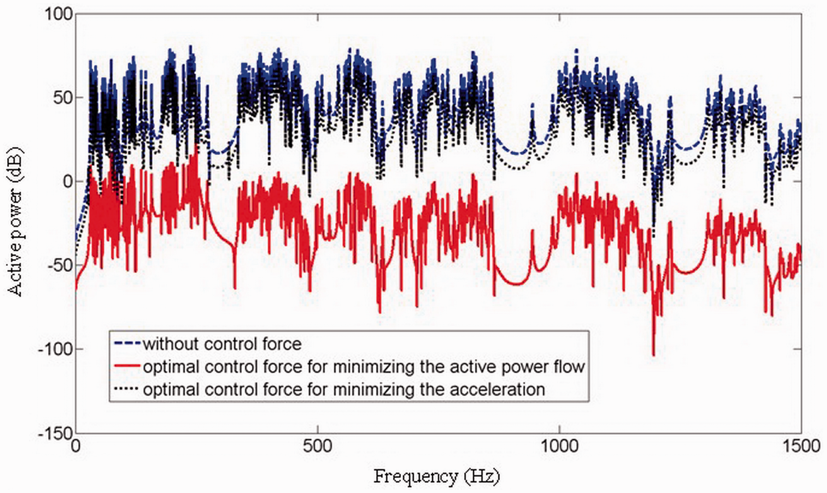
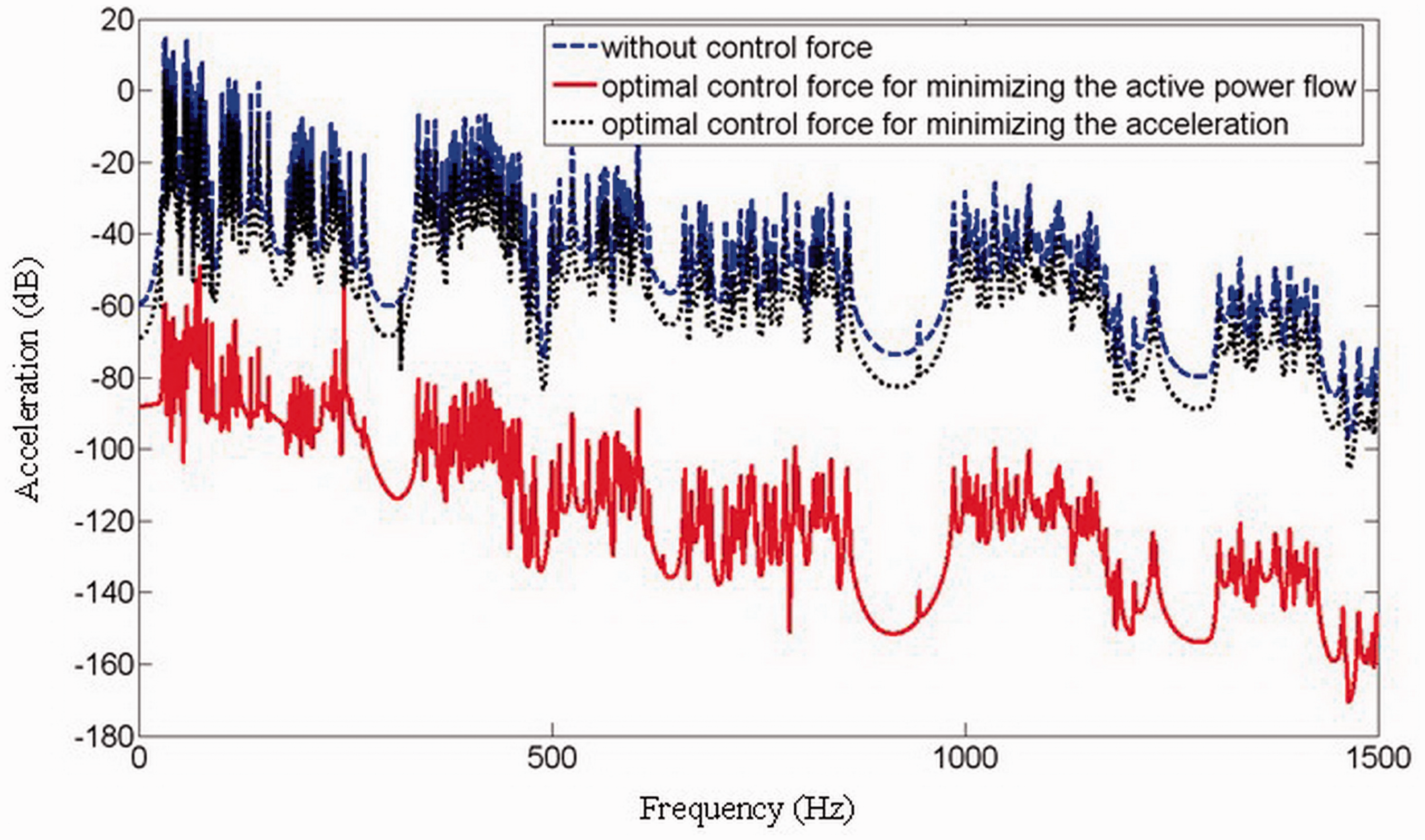
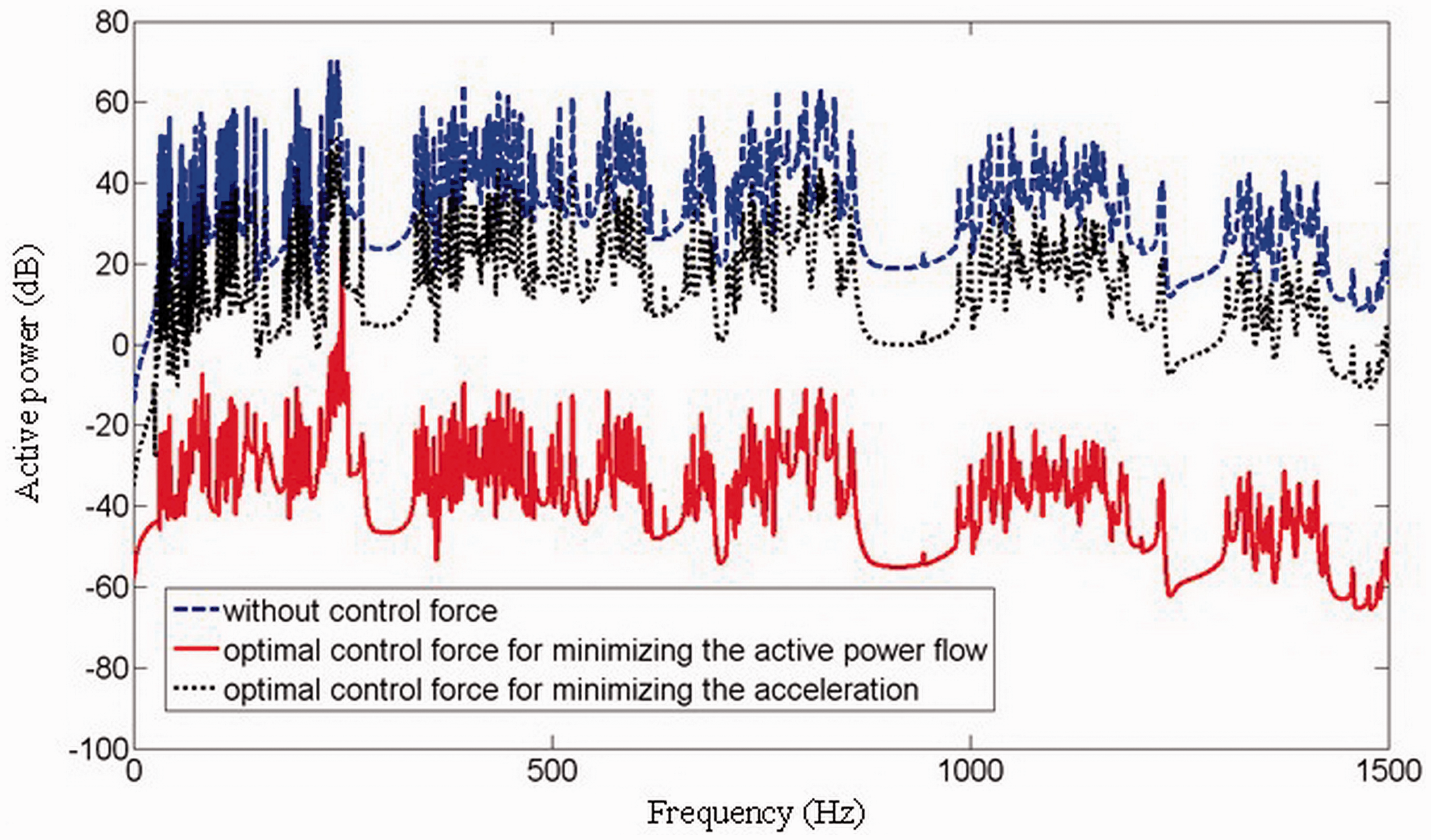
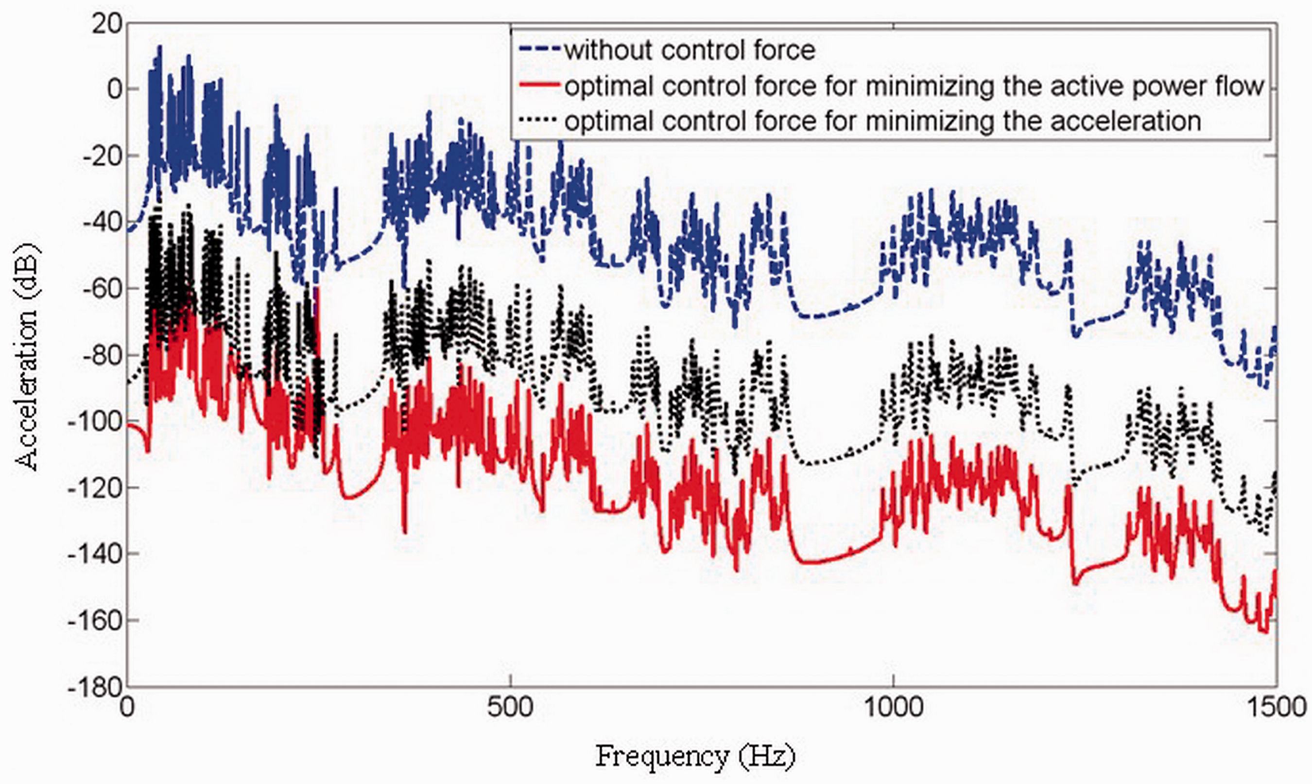
Figures 6 and 7 show the control effects of the active power flow and acceleration at the mid-point of beam 25 by the optimal control force for minimizing the active power flow and the acceleration at the location of the error sensor, where the error sensor (located at xe = 1 m of beam 4) is located in the near field of the control source (located at xs = 0.5 m of beam 4). As shown in Figure 6, the active power flow cannot be suppressed by the optimal control force for minimizing the acceleration in all the frequency regions. But the control effect of the optimal control force for minimizing the active power flow is very good in all frequencies. In Figure 7, the control effects of acceleration by the optimal control force for minimizing the active power flow and the acceleration are similar to those in Figure 6. Therefore, it indicates that the control effect of the active power flow and acceleration by the optimal control force for minimizing the active power flow is better than that achieved by the optimal control force for minimizing the acceleration where the error sensor is located in the near field of the control source (Schwenk et al., 1994; Liu et al., 2010a,b).
Active control of the active power for space truss structure with different control forces where the error sensor is located in the near field of control source, (dB ref:
Active control of the acceleration for space truss structure with different control forces where the error sensor is located in the near field of control source, (dB ref:
In Figure 8 and 9, active control with different control forces is investigated to suppress the active power flow transmission and acceleration at the mid-point of beam 5, where the error sensor (located at xe = 0.4 m of beam 5) is located in the far field of the control source (located at xs = 0.5 m of beam 4). The control forces are obtained by minimizing the active power flow and the acceleration, respectively. As shown from Figure 8, even if taking account into the error sensor located in the far field, the active power flow cannot be suppressed satisfactorily by the optimal control force for minimizing the acceleration, and the control effect is weak at many frequencies. However, the active control of power flow is still very effective in this case. It shows that the acceleration can be completely suppressed by the optimal control force for minimizing both the active power flow and acceleration in Figure 9. The acceleration results by the active control of power flow are better than those obtained by the active control of acceleration (Schwenk et al., 1994; Liu et al., 2010a,b).
Active control of the active power for space truss structure with different control forces where the error sensor is located in the far field of control source, (dB ref:
Active control of the acceleration for space truss structure with different control forces where the error sensor is located in the far field of control source, (dB ref:
5. Conclusions
The displacement responses and active power flow transmission of the complex space truss structure are investigated based on the advanced Timoshenko theory by the traveling wave method. The disturbance propagation of space truss structures is suppressed by active control for minimizing the active power flow. The results of the work are as follows:
The displacement responses of the complex space truss structure in the medium and high frequency ranges can be accurately calculated by the traveling wave method, and the computational efficiency of the method is higher than that of FEM. The simulation results show that the resonance frequencies obtained by the Timoshenko theory are lower than those calculated by the classical Euler-Bernoulli theory with the effects of rotary inertia and shear distortion. The Timoshenko beam model is more accurate for dynamic analysis of the space truss structure due to its more complete representation of the beam behavior. Hence the analysis is applicable to both low and high frequencies and the results are closer to outcomes of practical engineering. The active power flow through the arbitrary location of the space truss structure can be effectively suppressed by the control force for minimizing the active power flow in the whole frequency range, and the active power flow of the whole structure also can be well attenuated. The small error of the optimal control force for minimizing the active power flow has slight influences on the control effect. The active control based on the acceleration can control the acceleration and the active power flow at many discrete frequencies, only when the error sensor is located in the far field of the control source. However, the active control based on power flow can effectively control the active power flow and acceleration, whether the error sensor is located in the far field or near field. And the control effects by minimizing the active power flow are better than those obtained by minimizing the acceleration even if the error sensor is located in the far field.
Footnotes
Funding
This work was supported by the National Natural Science Foundation of China (grant numbers 50975056 and 11072066).