
Abstract
This work concerns a two-level procedure for the global optimum design of hybrid elastomer/composite modular structures. The goal of the procedure is the maximization of the first Nf modal loss factors of the structure, satisfying mechanical constraints on the weight and on the bending stiffness, feasibility constraints on the admissible moduli for the constitutive laminates, along with geometric constraints on the positions of the viscoelastic patches. At the first level of the procedure, the optimization of the damping behavior of the structure is carried out: the optimization variables at this stage are the number of elastomer patches (modules), as well as their geometrical parameters (position, thickness and diameter), along with the material and geometric parameters of the composite laminated structure (elastic moduli, thickness of the laminate). The composite structure supporting the elastomer patches is thus optimized using a free-material approach, via the polar representation of 2D elasticity, and the second level of the optimization consists in finding the laminate stacking sequence satisfying the optimal elastic moduli and thickness issued from the first step. The method is able to automatically determine the optimal number of modules and it does not need the introduction of any simplifying assumption. The proposed approach relies on one hand, on the application of the well-known Iterative Modal Strain Energy (IMSE) method for the evaluation of the dynamic response of the structure, and on the other hand on the use of the polar formalism for the representation of the elastic anisotropic behavior of composite laminates as well as of a genetic algorithm as optimization tool to perform the solution search. We will illustrate the application of our approach to the optimization of the damping behavior of a rectangular composite plate with a discontinuous aperiodic distribution of viscoelastic material. The numerical results show the effectiveness of the proposed strategy.
Keywords
1. Introduction
One of the most important challenges for automotive and aerospace industries is the reduction of noise pollution. In particular, the vibrations of the structural parts composing a system represent one of the major sources of noise: when structural components move, they produce noise. Moreover, due to their lightness and their high stiffness, composite materials are very sensitive to this phenomenon.
To this purpose, several passive solutions were proposed in recent literature: among them, a possible strategy consists of bonding elastomer patches on some well-chosen regions of the structure. Even though these solutions are proven to be quite effective (Zheng et al., 2004), they are often the result of a design process made a posteriori; that is to say, the structure was already designed or even optimized with respect to some criteria, and a posteriori a solution for the reduction of noise was sought by the introduction of a fixed number of viscoelastic patches of variable size and position. If, on the one hand, the bonding of new elastomer elements onto the original structure improves its damping behavior, on the other hand it increases its weight, and it might affect its mechanical properties.
To overcome such an issue, Kerwin (1959) was one of the first researchers who considered the design of sandwich beams including a priori viscoelastic layers. Solutions of this kind have been widely studied in the literature and have proven to be rather effective (Rao, 1978; Lu et al., 1979; Ghoneim and Karkoub, 2001; Chalak et al., 2011). Rather complete, though not exhaustive reviews on this subject can be found in Nakra, 1998; Chandra et al., 1999; Berthelot et al., 2008; Vasques et al., 2010a; Vasques et al., 2010b; Benjeddou, 2001; Trinidade and Benjeddou, 2002. Moreover, concerning both active and passive strategies for designing the damping properties of hybrid composite/elastomer sandwich plates, the reader is addressed to Araújo et al., 2009; Araújo et al., 2010; Araújo et al., 2012; Sher and Moreira, 2013.
The majority of the studies conducted on hybrid elastomer/composite systems consider only the presence of continuous viscoelastic layers within the stack of the laminates composing the structure. To the best of our knowledge, the first researchers that investigated the effects of using discontinuous viscoelastic layers were Kristensen et al. (2008) who studied the problem of composite beams damped by discontinuous rubber layers (or patches) in two different cases: the case wherein the gaps between the patches are filled by composite material and the case wherein such gaps are unfilled. The authors highlight the importance of using continuous viscoelastic layers in order to obtain high damping capabilities. They considered a beam made of three layers (the bottom one represents the composite beam, the middle one the viscoelastic layer and the top one the so-called constrained stiffer layer) and they showed that “cutting” away parts of the rubber layer in particular regions of the structure, e.g. in the regions where the loads and/or the supports have to be applied, does not allow the amelioration of the damping capabilities of the system, but, on the contrary, it might induce a broad reduction of such capabilities, depending on the region where the material is cut away. In addition, they asserted that an important parameter involved in the mechanism of the dissipation of the vibratory energy is the thickness of the stiffer constrained layer rather than the thickness of the rubber one. They showed that, when keeping constant the thickness of the rubber ply and increasing the thickness of the stiffer layer, shear strains are forced into the viscoelastic ply which are responsible for the energy dissipation. Finally, they showed that the case of the beam with discontinuous rubber layers having gaps filled by composite material shows better damping capabilities than those of the case with unfilled gaps.
Despite the fact that the work of Kristensen et al. (2008) presents several innovative points along with some interesting results, it is worth noting that the mathematical model adopted to describe the beam kinematic (based on the Timoshenko assumptions) does not take into account correctly the orthotropy of the elastic plies (in fact in that work the material behavior of such plies is described only through two parameters, i.e. a Young’s modulus E and a shear modulus G). Moreover, the behavior of the viscoelastic material is described using the well-known Kelvin–Voigt model, which is not able to represent the relaxation behavior of the rubber ply. In addition, the mechanical model employed in that work considers as primary source of damping only the mechanism associated to the shear deformations through the thickness of the viscoelastic material, thus neglecting the contribution of the other strain components. Together with the previous aspects, one can notice that the level of shear strains forced by the stiffer layer into the elastomer one is too high, and hence the non-linearity of the model (either geometrical or material) must be taken into account in the calculations. Finally such a study is conducted considering only the influence of all design parameters on the first modal loss factor of the structure, ignoring the effect on the other loss factors associated with higher frequencies: it seems natural that the results found by the authors can be valid only when considering the damping mechanism at low frequencies.
Recently, LeMaoût et al. (2011) studied the problem of laminated plates damped by using rubber patches: more precisely the main goal of that work is the maximization of the modal loss factors of the structure (in a given range of frequencies) employing a periodical pattern of viscoelastic material. They considered a three-layer plate with the following design variables: thickness and orientation angle for the elastic plies and thickness, and diameter and distribution for the rubber patches (they assumed that the patches were identical and equally spaced). The modal loss factors were evaluated according to the well-known Iterative Modal Strain Energy (IMSE) method. Also in this work two different cases were considered: the case wherein the gaps between the patches are filled by composite material and the case wherein such gaps are unfilled. In both cases, the results (in terms of the damping capability of the structure) are compared with those obtained using continuous viscoelastic plies. The authors showed that a simultaneous design of both elastic and viscoelastic properties of the structure can lead to obtaining better damping capabilities with respect to the case of employing continuous viscoelastic layers.
Even though the work of Le Maoût et al. is characterized by some original aspects, the optimization problem is solved introducing the aforementioned simplifying assumptions (identical and equally spaced patches, three-layer plate) which could affect the quality of the final solution.
The study presented in this work could be placed within the context of the works originally proposed by Le Maoût et al. and can be seen as a generalization and also as an extension of those works. In particular we propose a global optimization technique for the design of damping properties of hybrid elastomer/composite modular structures, i.e. composite laminated plates equipped with bonded elastomer patches. The goal of the procedure is to maximize the first Nf modal loss factors of the structure subject to various constraints: on the flexural stiffness, on the weight of the plate, on the material design variables describing the behavior of the composite plate and, finally, on the position of the patches over the composite plate.
The problem considered here belongs to the class of design problems of modular systems. The hybrid elastomer/composite structure studied here has two different types of modules. The modules of the first type are the patches. All the patches are modules because they have the same function and geometry, but not necessarily the same size (diameter and thickness), nor the same position. In addition the number of patches is included among the design variables of the optimization problem. The modules of the second type are the layers: all the layers, composing the composite plate, are identical (same constitutive material and same thickness), but normally they are differently oriented.
We adopt a two-level procedure for the global optimum design of the hybrid structure. This procedure has already been employed to treat other optimization problems concerning modular composite structures (see Montemurro et al., (2012a); Montemurro et al., (2012b), for more details). At the first level of the procedure, the optimal design of the hybrid elastomer/composite structure in terms of its damping capabilities is carried out, the design variables in this phase being the geometrical parameters characterizing each patch-module (number, position, thickness and diameter) along with the material and geometric parameters describing the composite plate that is considered as an equivalent single layer (these parameters are the laminate polar moduli and the total thickness of the plate). At the second level of the procedure we look for at least one stacking sequence corresponding to the optimal elastic moduli and thickness found for the composite plate at the first level. The proposed approach relies on one hand, upon the dynamic response of the structure in terms of natural undamped frequencies and modal loss factors, which are evaluated using the IMSE method, and on the other hand on the use of the polar formalism for the representation of the elastic anisotropic behavior of composite laminates as well as of the genetic code BIANCA with crossover and mutation between different species (Vincenti et al., 2010; Montemurro et al., 2012b; Montemurro et al., 2013) as an optimization tool to perform the solution search.
The paper is organized as follows: the mechanical problem considered in the study as well as the two-level strategy are introduced in Section 2. The mathematical formulation of the first-level problem is detailed in Section 3 and the problem of determining a suitable laminate is formulated in Section 4. A concise description of the finite element (FE) model of the hybrid structure is given in Section 5, while in Section 6 we show the numerical results of the whole optimization procedure. Finally, Section 7 ends the paper with some concluding remarks and perspectives.
2. Optimal design of composite plates with bonded elastomer patches
2.1. Description of the problem
The optimization procedure presented in this work is applied to the hybrid structure depicted in Figure 1.
Geometry and design variables of the hybrid structure.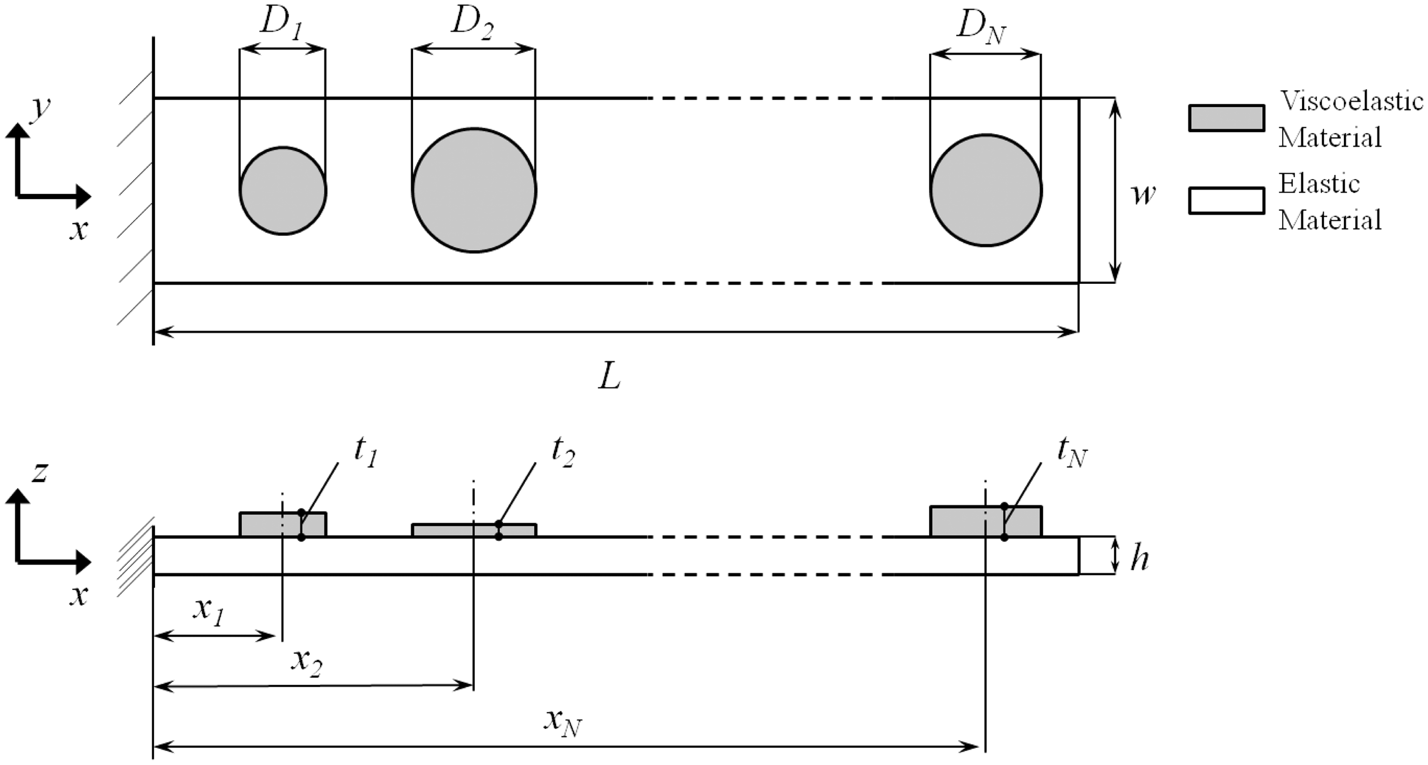
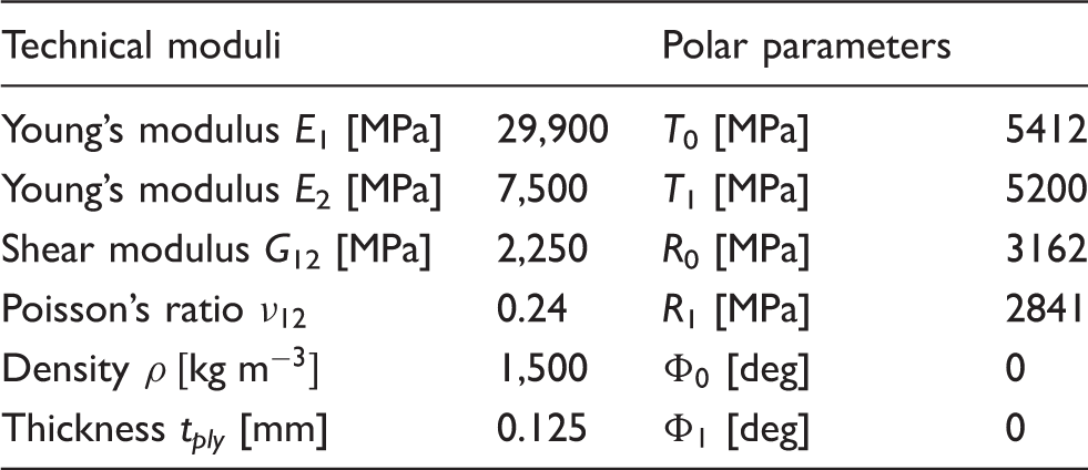
Material properties of the glass-epoxy lamina.
For evident mechanical reasons, we assume that the laminated plate is quasi-homogeneous and fully orthotropic, with the main orthotropy axis aligned with the x-axis of the structure. The definition of a quasi-homogeneous laminate is given in Section 3.
In addition, no simplifying assumptions are made on the structure nor on the patches: indeed all patches can be different, in terms of their geometrical parameters. The material used for the viscoelastic patches is a rubber-like material having linear isotropic behavior. In addition, the material properties depend upon the loading frequency f and they are taken from Zhang and Chen (2006). The variation of the complex Young’s modulus with the frequency, E(f), is expressed as:
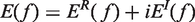
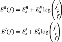
The superscripts R and I stand for real and imaginary part, respectively. The subscripts s and d represent the steady-state value and the amplitude of the part that depends upon the frequency for both the real and imaginary part of the Young’s modulus, while
For our work, we fix the values of parameters in equation (1) according to Zhang and Chen (2006): 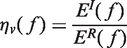
2.2. Description of the two-level optimization strategy
The design procedure that we propose is inspired by a radical point of view: to develop a mathematically rigorous procedure for the optimum design of modular hybrid structures without the need of simplifying assumptions. Only avoiding the use of a priori assumptions one can hope to obtain the true global optimum for a given problem: this is a key-point in our approach. The design process that we propose is, on one side, not submitted to restrictions introduced artificially to simplify the problem itself, and, on the other side, completely automatic: the designer does not need to make any preliminary decision, for instance, on the number of the patches or of the layers, because the method will do that automatically. In fact, the approach presented in this paper can also optimize the number of modules and, hence, the number of design variables.
The objective of our problem is the maximization of the damping capabilities of the structure (in terms of the first Nf modal loss factors) with constraints on the minimum admissible stiffness and on the maximum admissible weight. Concerning the organization of the whole optimization procedure, the problem of designing the damping properties of the hybrid structure is formulated into two distinct problems:
In the following sections, we will give a detailed description of the mathematical formulation of the optimization problems for both the first and the second steps of the procedure.
3. Mathematical formulation of the first-level problem
The overall characteristics of the optimal structure have to be designed during this phase. For the problem at hand, this means that in this phase we have to determine the optimal values of the following parameters:
the number of viscoelastic circular patches; the geometrical properties (position, diameter and thickness) of each patch; the thickness, and hence the number of layers, of the laminated plate; the elastic properties of the laminate, namely the anisotropic polar moduli of the plate.
Hence, we need to determine the optimal number of modules, i.e. of viscoelastic patches: patches can have different positions and different sizes.
It is worth noting that, for sake of simplicity, we only consider circular patches. Indeed, the aim of this study is to demonstrate the relevance of using patches to damp composite plates and not to discuss their possible geometry. More precisely, circular patches do not need the introduction of the orientation as an additional design variable for each patch, so this choice minimizes the number of geometrical characteristics of the patches.
We can also remark that during this stage of the optimization procedure, the thickness h of the composite plate must be considered as a discrete optimization variable, the discretization step being equal to the thickness of the material layer used for the fabrication of the laminate (see Table 1). Of course, this responds to a technological need, and, moreover, this will give us also another important result: the optimal number of layers n to be used during the second-level design phase.
The maximization of the first Nf modal loss factors of the structure must be done satisfying, on one side, the mechanical constraints on the bending stiffness and on the weight of the structure, and, on the other side, the geometric bounds for the elastic moduli along with the geometric constraints on the position of the center of each patch. Such aspects are described in detail in the following subsections.
3.1. Geometrical design variables
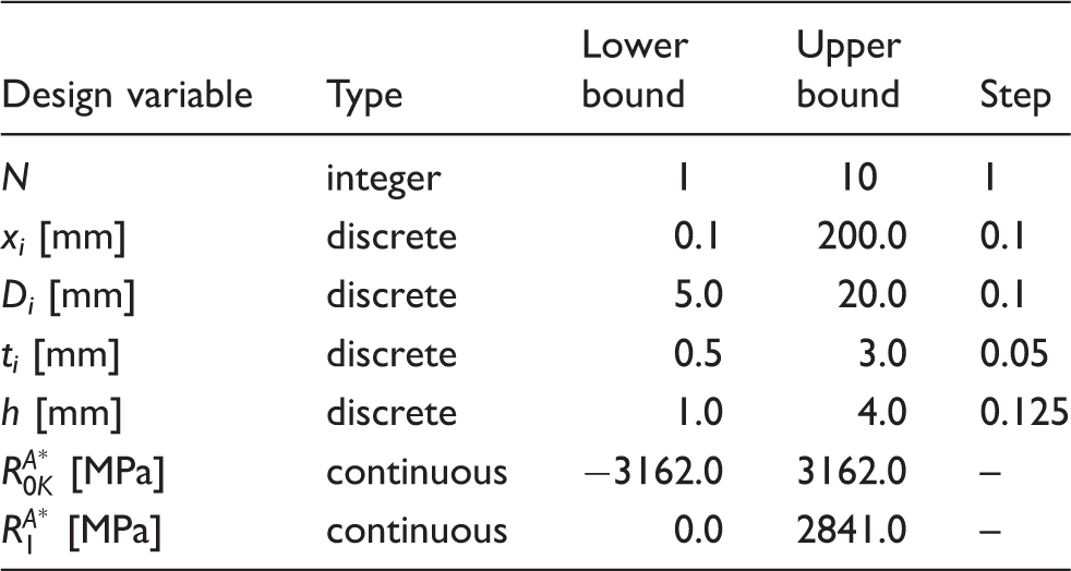
Before specifying the mathematical formulation of the first-level problem, we introduce the design variables. These are of two types: geometrical and mechanical. Concerning the geometrical design variables, they are shown in Figure 1 and are:
the number of patches N; the position of the center of each patch xi, the diameter Di and the thickness ti of the generic patch, the thickness of the laminated plate h.
Design space for the first-level problem.
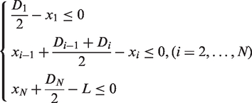
It is worth noting that the viscoelastic patches cannot have an arbitrary distribution over the plate, but they must satisfy certain geometrical conditions in order to avoid overlapping between two consecutive patches. Moreover, we have to impose the requirement that the patches remain inside the length of the plate. Such constraints can be written as follows:
3.2. Mechanical design variables
Concerning the mechanical variables, we use the polar formalism, which gives a representation of any planar tensor by means of a complete set of independent invariants. These invariants are called polar parameters, and a great advantage in the design of anisotropic structures is that they are directly linked to the different symmetries of the tensor (Verchery, 1979; Vannucci, 2005).
By the polar formalism, the reduced stiffness tensor 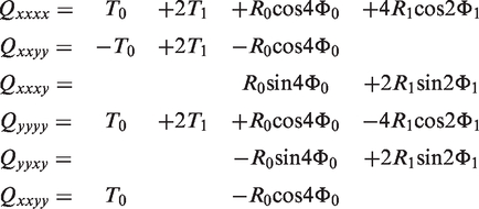
In equation (4), T0, T1, R0, R1,
The Classical Laminated Plate Theory (CLPT) gives the constitutive law of a laminate, linking the internal actions to the deformations of the laminate:
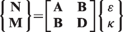
In (5), 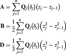
The previous laws are independent from the tensor representation and hence apply also to the polar formalism. Some standard passages (see Vannucci (2005)) give then the polar parameters of tensors 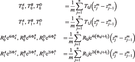
As already said, in this work we use a quasi-homogeneous, orthotropic laminate for the composite plate. Introducing the normalized stiffness tensors, defined as:
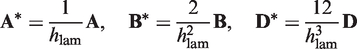
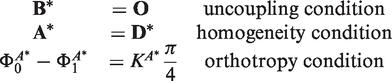
The quasi-homogeneity condition ensures that the laminate has identical in-plane and bending behaviors: in this case the design domain of elastic moduli is the same for in-plane and bending, and one single set of polar invariants can describe both elastic behaviors. Quasi-homogeneous laminates are a well-known class of laminates, that are widely used in the design of flexural properties (Vannucci and Verchery, 2001).
A simple result of the polar formalism is that, for the general case of laminates with identical layers, the isotropic moduli of the normalized in-plane and bending behavior
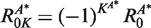
From the third condition of equation (9), we get:
Moreover, we have to impose that the main orthotropy axis of the laminate is aligned with the x-axis of the structure. This condition can be stated as follows:

In this first level of the procedure, we must also introduce the geometric and feasibility constraints on the polar parameters, which arise from the combination of the layer orientations and positions within the stack. These constraints assure that the resulting optimal polar parameters can correspond to a feasible laminate, which can be designed during the next second step of the optimization procedure. Such bounds can be written independently for tensors
We recall here the expression of such constraints (the quantities without the superscript 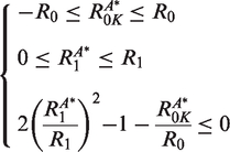
It is worth noting that the first two bounds of equation (13) can be easily taken into account as box-constraints, i.e. by properly setting the range of variation of the polar quantities
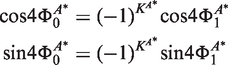
We add a conclusive remark about the quasi-homogeneity assumption: thanks to the first two conditions of equation (9), we can impose the orthotropy condition directly on the polar angles of tensor
Thus, by imposing the quasi-homogeneity condition we are able, during the first phase, to reduce to only three polar parameters the set of mechanical design variables which completely describe the behavior of the laminate.
In addition, a second important advantage arises from the quasi-homogeneity condition: only thanks to this assumption we are able to mathematically formalize the set of geometric and feasibility bounds of equation (13) that the laminate has to satisfy. In fact, to the best of our knowledge, only imposing the quasi-homogeneity condition we can write, explicitly and independently for tensors
Finally, it is worth noting that through the use of the polar formalism, it is possible to optimize directly the homogenized tensors representing the material properties of the composite laminated plate without considering the underlying stacking sequence. The choice of the optimization variables shown in this paragraph, as well as the introduction of the optimization constraints of equation (13), are equivalent to a free-material optimization of the composite laminated plate: for a more detailed discussion on the application of the polar method to free-material optimization of composite structures see Julien (2010); concerning more generally the free-material approach of composite laminates, one can see for instance Bendsøe et al. (1995), Hörnlein et al. (2001), or Hvejsel et al. (2011).
3.3. Mathematical statement of the problem
As said previously, the goal of the global structural optimization is the maximization of the damping capabilities of the structure without degrading too much its stiffness nor increasing too much its final weight.
The damping capabilities are estimated in terms of modal loss factors of the structure
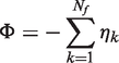
The optimization problem can now be formulated. The maximization of the first Nf modal factors can be expressed as the minimization of the following objective function:
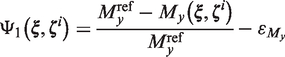
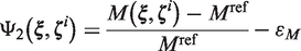
Along with the increase of the damping capabilities, the structure must exhibit good properties in terms of stiffness. Indeed, the design of the hybrid structure represents a compromise between its damping capability and the ability of keeping good mechanical properties in terms of stiffness, without increasing too much its weight. This can be done, for instance, introducing constraints on the maximum decrease of the bending stiffness and on the maximum increase of the mass of the plate:
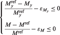
In equation (15) My is the bending moment around the y-axis measured at the root section of the plate when a unitary displacement Static test for the evaluation of the bending moment: imposed unitary displacement along z-direction.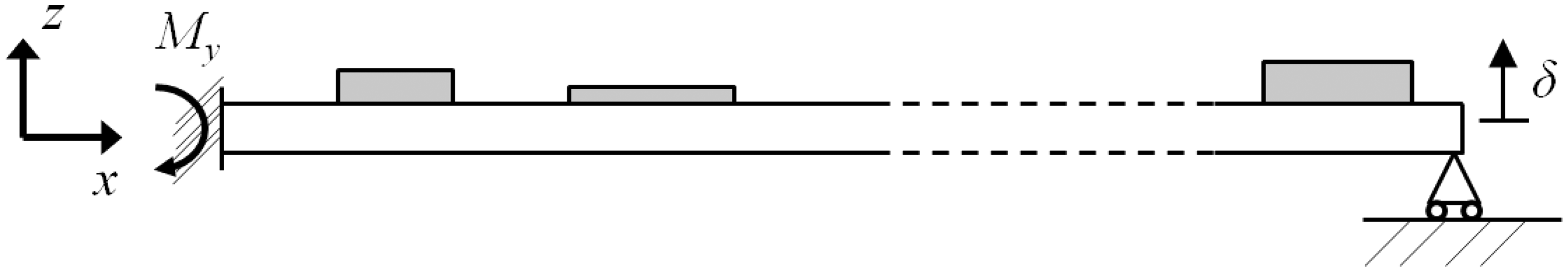
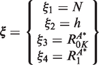
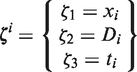
To state the optimization problem in a standard form, firstly we reorder the design variables according to the following scheme:
The vector Each one of the vectors
Then, we introduce the following functions:
the objective function Φ, expressing the damping capabilities of the structure: the functions expressing the two constraints (15) on the bending stiffness and on the weight: the functions expressing the five geometric constraints (13) on the polar parameters of the plate: the functions expressing the N + 1 geometric constraints (3) on the positions of the patches bonded over the plate:
Finally, the problem can be stated in the standard form:
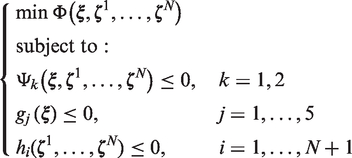
Problem (29) is non-linear, in terms of both geometrical and mechanical variables. Its non-linearity is given not only by the objective function but also by the geometrical constraints on the laminate polar parameters as that in equation (25) and by the mechanical constraints on the bending moment and on the weight of the structure (see equations (19) and (20)).
Finally, the dimension of the design space, i.e. the number of design variables, and the number of constraint equations depend on the number N of patches. In particular, the total number of design variables is
A final remark about the numerical strategy employed for the solution search: for the resolution of problem (29) we use the new version of the genetic code BIANCA (Montemurro et al., 2012b). In the case of the first-level problem we need the use of the new genetic operators of crossover and mutation between individuals belonging to different species (see Montemurro et al., 2012a; Montemurro et al., 2012b). In fact, since the number of viscoelastic patches N is included among the design variables, the related optimization problem is defined over a space having variable dimension (the dimension of such a space is
Figure 3 shows the genotype of the generic Structure of the individual genotype for the first-level optimization problem.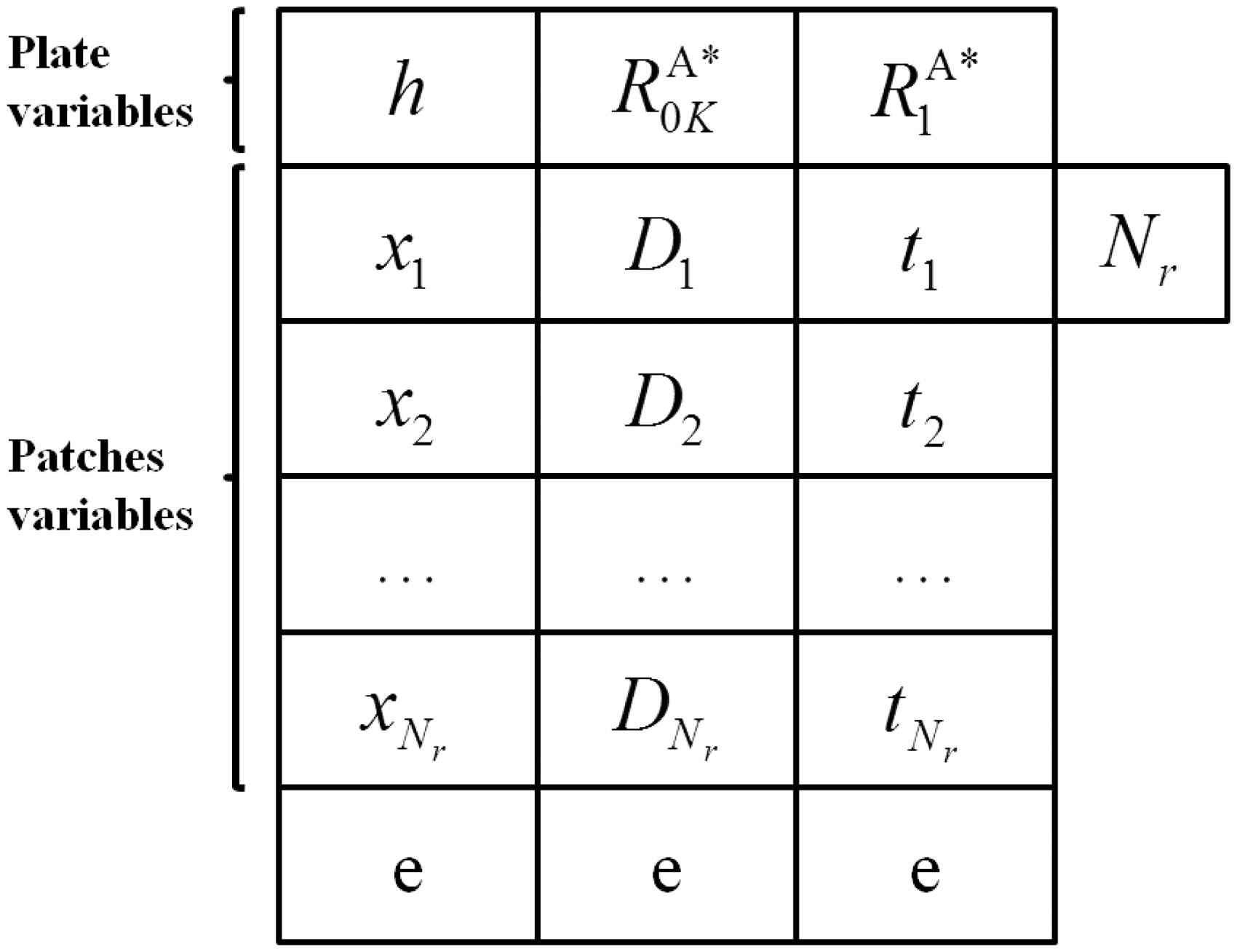
Since Nr is a variable of our problem, the size of the individual, i.e. the number of chromosomes, is variable, which means that different individuals within one population of the genetic algorithm can belong to different species. Symbol e in Figure 3 represents “empty” or inactive genes corresponding to the variable number of constitutive patches/chromosomes for the current individual.
4. Mathematical formulation of the second-level problem
The main focus of the second-level phase concerns the design of the laminated plate in terms of its stacking sequence. Of course, this second problem depends upon the results of the first one, because the laminate to be designed must have the optimal elastic properties and thickness issued from the first-level design problem and additionally it must satisfy the conditions on the elastic symmetries (orthotropy and quasi-homogeneity) introduced in the mathematical formulation of the first-level problem.
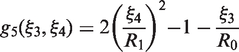
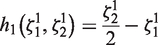
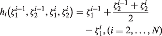
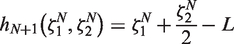
In this phase the problem of designing the laminate stack is formulated as an unconstrained minimization problem. Therefore, the key point of the second-level problem is the construction of the objective function that drives the search for a quasi-homogeneous, orthotropic laminate, having the optimal elastic polar moduli issued from the first step, i.e.
All the mathematical details of the second-level problem can be found in Montemurro et al. (2012a). Here, we recall only the expression of the objective function that assumes the following form:
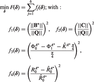
In (30),
The genetic algorithm BIANCA has also been used in this second step of the procedure. The structure of the genotype of the individual-laminate is shown in Figure 4. The genotype is made of n chromosomes, which correspond to the n constitutive layers of the laminate (n is determined in the first step) and each chromosome is composed, in its turn, by a single gene which represents the ply orientation.
Structure of the individual genotype for the second-level optimization problem.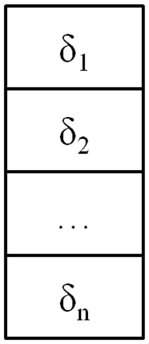
As a conclusive remark, it is worth noting that the optimal thickness of the laminated plate is a result of the first-level problem. Since we defined the plate thickness as a discrete variable, which is an integer multiple of the thickness of the elementary ply, then the optimal number of constitutive layers is also known.
5. Finite element model of the hybrid structure
The finite element (FE) analysis is conducted in order to evaluate the objective and constraint functions for each individual, i.e. for each point in the design space at the current generation. The FE model is built in ANSYS environment (see Figure 5). The need to analyze, within the same generation, different geometrical configurations (plates with different number of patches of different size at different positions), each one corresponding to an individual, requires the creation of an ad-hoc input file for the FE code, that has to be interfaced with BIANCA. Since the number of modules is included among the decision variables, the FE model must be conceived so as to take into account variable geometry and mesh. Indeed, for each individual at the current generation, depending on the number of chromosomes and, hence, on the number of patches, the FE code has to be able to vary in the correct way the number of elements wherein the structure is discretized, thus a correct parametrization of the model has to be achieved.
Mesh and rigid constraint equations for the FE model of the structure.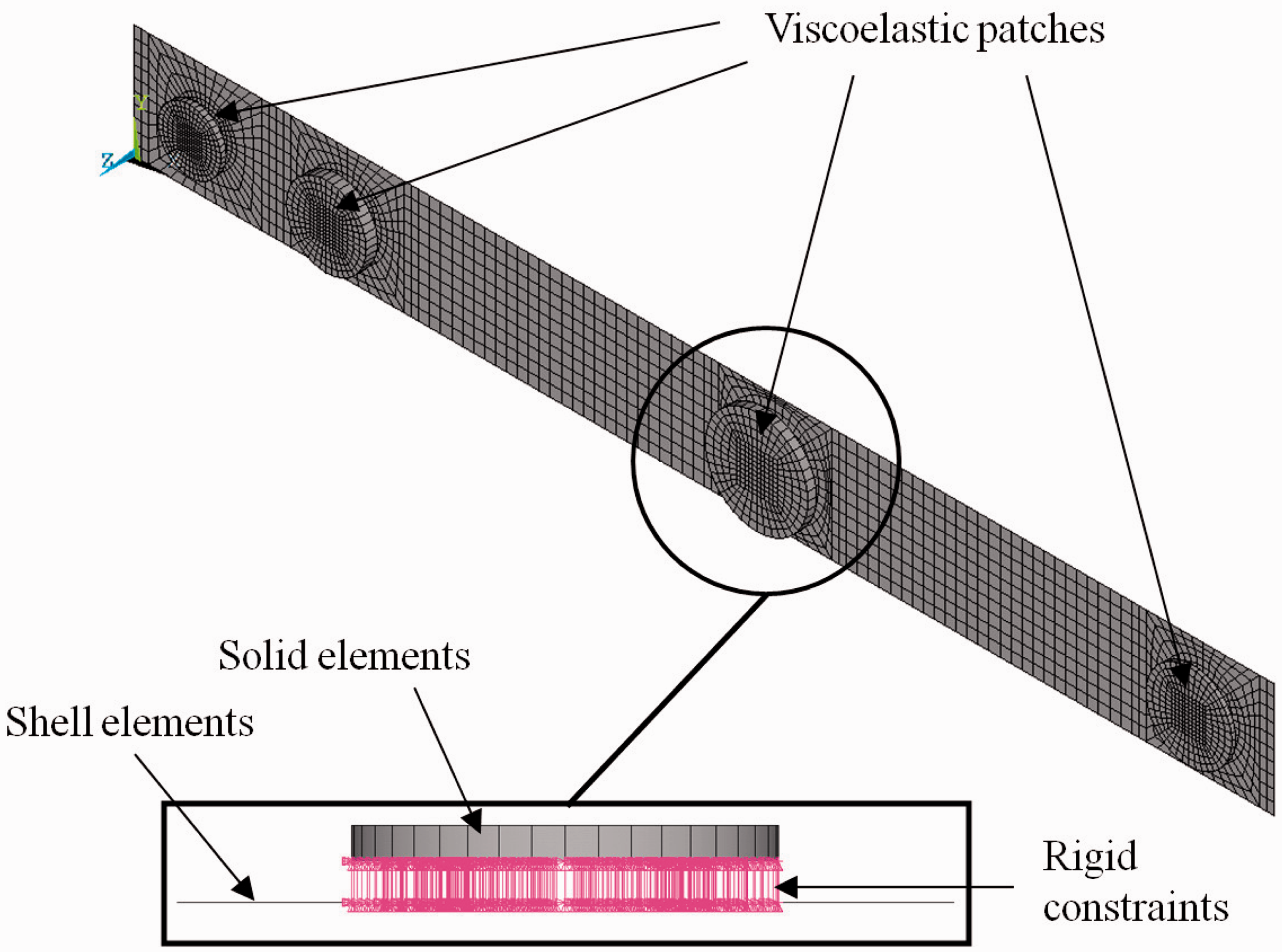
The structure is modeled with a combination of shell and solid elements. In particular, the laminate is modeled using ANSYS SHELL99 elements with eight nodes and six degrees of freedom (DOFs) per node, and its mechanical behavior is described specifying the Cartesian components of tensors
The choice of using solid elements to model the viscoelastic patches is strictly related to the main goal of our optimization strategy: since we have to estimate the loss factors of the structure, for each natural frequency, we need to build a mathematical model able to describe (with a good level of accuracy and reliability) the mechanical response of the physical system, i.e. the energy dissipation due to the different components of the strain tensor.
It is worth noting that, during the optimization process, for each individual, we perform two FE calculations: a non-linear modal analysis, according to the logical flow of the IMSE method already presented in (Montemurro et al., 2012), together with a linear static analysis in order to compute the reaction moment My, according to the scheme shown in Figure 2. Concerning the boundary conditions (BCs) of the model, these can vary depending on the considered case-study, as we will explain in the next section. In any case, the extraction of the first
We recall that the number of elements as well as the number of DOFs of the whole structure depends on the number of patches N. In particular, the size of the shell elements can vary over the plate surface: in the regions without the viscoelastic patches the sizes of the shell elements are
Opposed to what is usually done in the literature, we do not need to create fictitious elements to model the “air”, which are used to fill the gaps between the elements that constitute the elastomer patches. With a correct parametrization of the FE model, in terms of geometry and mesh, we can avoid all these difficulties, and we are able to consider the exact circular geometry of the patches, without considering polygonal approximation and without introducing additional elements with fictitious properties (the “air”) that can alter the results of the analyses.
As a conclusive remark, it can be noticed that the compatibility of the displacement field between the patches (modeled with solid elements) and the plate (modeled with shell elements) is realized by means of constraint equations on each corresponding node belonging to contiguous solid and shell elements (see Figure 5). In particular, we specified rigid constraints between the nodes of the middle surface of the laminated plate and the corresponding ones of the bottom surface of the patches. Rigid constraint equations are specified according to the classical scheme implemented within the ANSYS code: the master nodes are those belonging to the middle plane of the composite plate, whilst the slave nodes are those located on the bottom surface of every patch. Through these constraint equations, the displacements of the nodes belonging to the top surface of the plate (in the region wherein the patch is bonded) are equal to those of the nodes belonging to the bottom surface of the patch.
6. Studied cases and results
For our optimization problem we have considered two cases of example. It is worth noting that each case is different from a conceptual point of view. More precisely, in the first example the laminated plate has not to be designed, and we must determine the optimal distribution of the rubber patches in order to maximize the damping capability of the system. In addition, this first example is articulated in two sub-cases that differ only in terms of the boundary conditions (BCs) applied on the plate in order to study their influence on the distribution of the patches.
On the contrary, in the second example we perform the simultaneous design of both the elastic and the viscoelastic parts of the structure, namely the laminate and the patches, in order to show that we can obtain a more effective optimal configuration in terms of damping capabilities of the system. We recall that the design variables, their nature and bounds for the optimization problem at hand are detailed in Table 2. Now, let us introduce the two examples:
We remind that the overall number of design variables depends on the number of patches N. Thus, for the present case we have
As said previously, since our aim consists in studying the influence of the BCs of the model on the optimal distribution of the patches over the plate, and, hence, their influence on the damping capabilities of the system, we consider two different sub-cases:
For the present case, the total number of design variables as well as the number of constraint equations depend on the number of patches N, as explained in Section 3: the number of unknowns can vary between 7 and 34, while the number of constraints varies between 9 and 18.
These test cases are chosen according to the problems often treated in the literature and also according to the will of testing new problems which are more general and complex than the ones already presented in the literature.
Concerning the optimization problem of equation (29), for the first example the laminated plate has a quasi-homogeneous, fully orthotropic unsymmetric stacking sequence made of 18 plies:
Concerning the second example, in order to establish correct reference values for the reaction moment around the y-axis and the mass of the hybrid plate, a static analysis is conducted on a reference structure before starting the optimization process. The undamped reference plate, i.e. a plate without elastomer patches, considered here is made of 32 glass-epoxy laminae (see Table 1 for the material properties) with the following stacking sequence:
As conclusive remark, it can be noticed that the user-defined tolerances on the constraints of the problem (29) are set as follows:
6.1. Example 1. Case 1(a): clamped quasi-homogeneous orthotropic plate
As said previously, in this case the laminated plate is clamped at the root section. Since the number of patches is variable and they are not identical, a crossover between species is required and the optimal value of N is an outcome of the search process: the most adapted species automatically issues as a natural result of the Darwinian selection in the genetic algorithm. The genotype of the individual for this case is the one shown in Figure 3 without the first chromosome coding the variables of the laminated plate, i.e. the thickness and the polar parameters.
Concerning the genetic parameters, the population size is
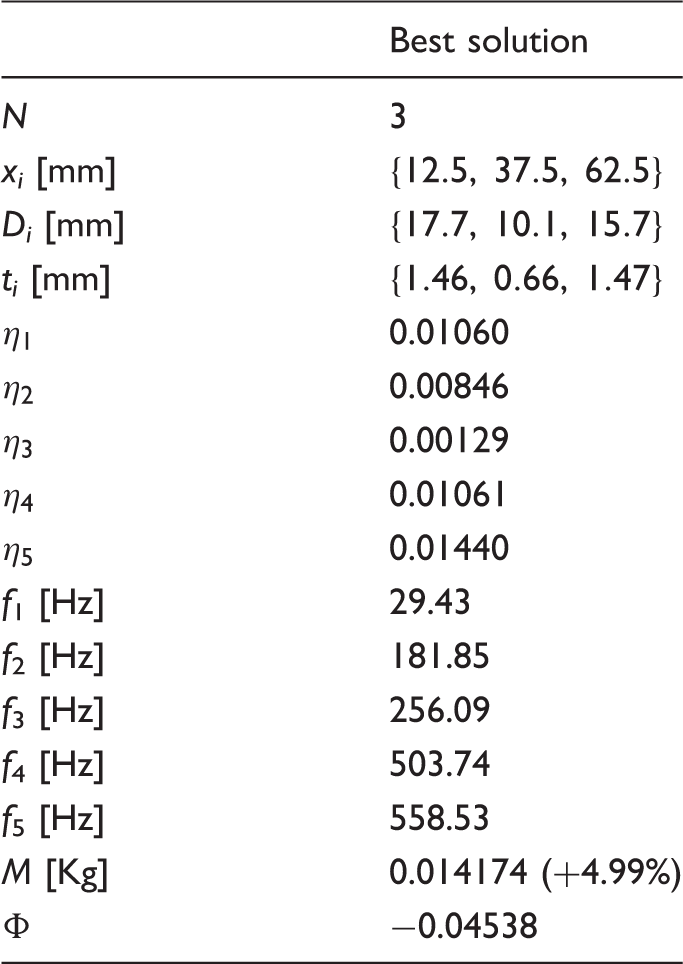
The best solution found by BIANCA is shown in Table 3. The optimal number of viscoelastic patches for the damping maximization is three. The global constrained minimum was found after 90 generations (see Figure 6(a)). Figure 6(b) shows the variation of the optimal number of viscoelastic patches along the generations: it can be seen that the best number of patches N varies between two and three, and that the optimal value of N is reached after 80 generations.
(a) Best values of the objective function and (b) optimal number of patches along generations for problem (29), Case 1(a). Best solution found using BIANCA for the optimization problem (29), Case 1(a).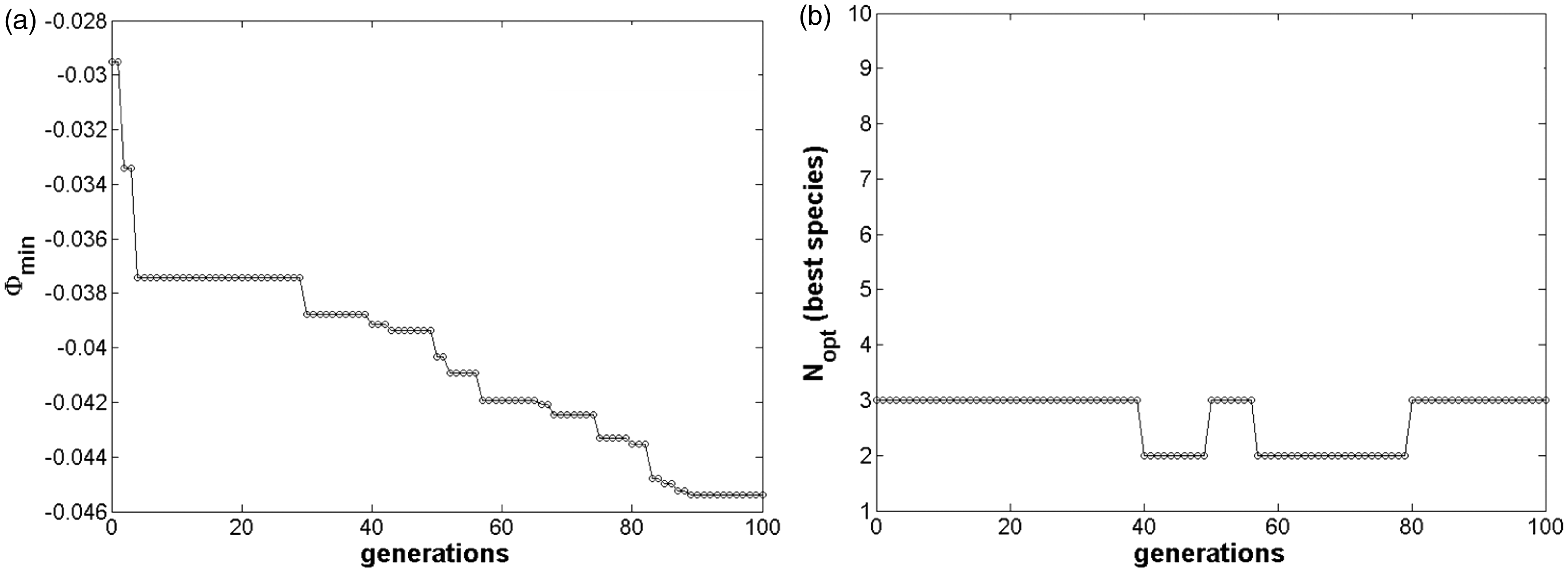
In addition, comparing the plots in Figures 6(a) and (b), one can notice that the convergence towards the best value of the number of modules (here, the number of patches) and that of the objective function are independent. They never occur at the same time, and the optimization of the number of modules happens always before that of the objective function. Thus we can conclude that the strategy used in BIANCA for evolving simultaneously species and individuals normally leads first to the result of the best species, and then continues to evolve individuals within the best species towards the best individual.
Figure 7 shows the best individual within the population (the best distribution of the patches over the plate for the present case), at the first and at the last generation. We can see that the sizes (diameter and thickness), the positions and the number of patches change during the generations.
Best distribution of viscoelastic patches at the (a) initial and (b) final generation (optimum) for problem (29), Case 1(a).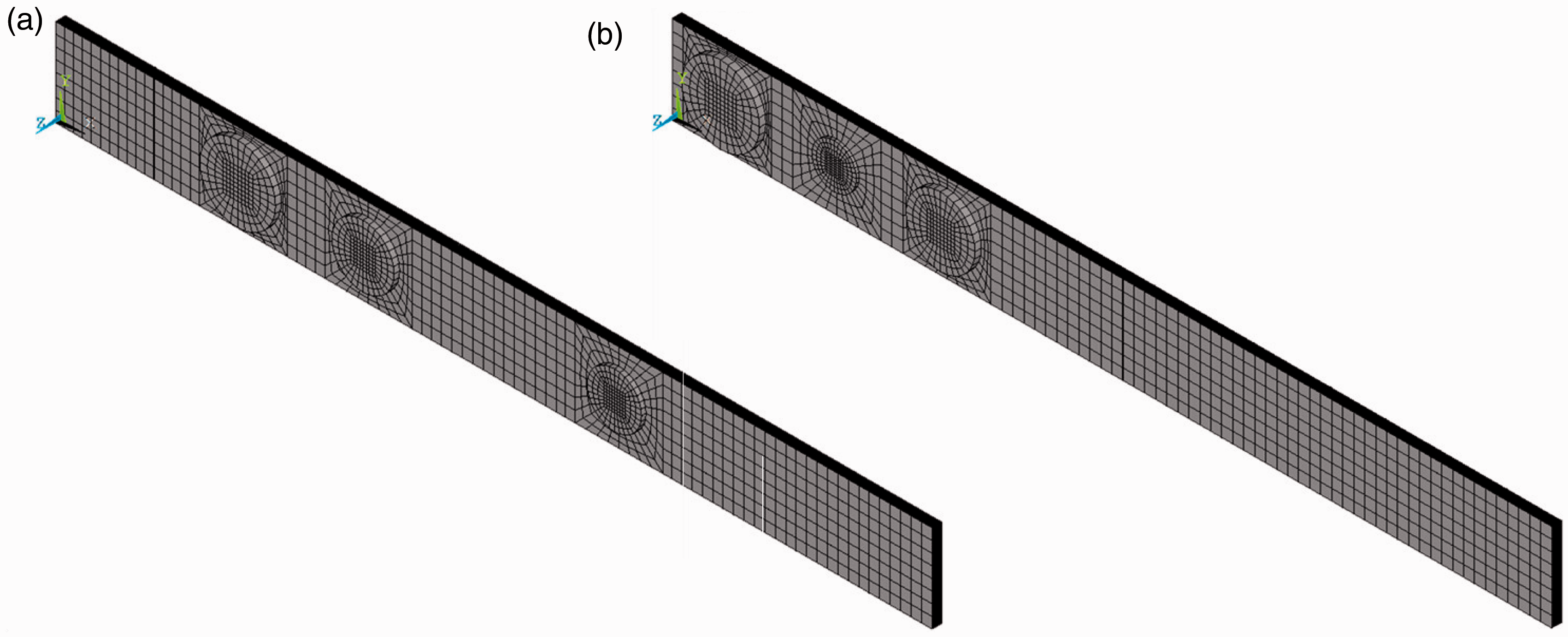
6.2. Example 1. Case 1(b): simply supported quasi-homogeneous orthotropic plate
In this second case the laminate is simply supported at its ends. The aim of such an example is to study how the distribution of the viscoelastic material changes when we consider different BCs for the model. The genotype of the individual and the genetic parameters are exactly the same as the previous case.
The best solution found by BIANCA is shown in Table 4. For this case, the optimal number of viscoelastic patches for the damping maximization is two. Figures 8(a) and (b) show the variation of the best solution and that of the best species along the generations, respectively. We can see that the global constrained minimum was found after 73 generations, while the number of viscoelastic patches N converges to its optimal value after 13 generations. Again, the convergence towards the best value of N and that of the objective function are independent, and the convergence towards the best species is faster than the convergence towards the best individual.
(a) Best values of the objective function and (b) optimal number of patches along generations for problem (29), Case 1(b). Best solution found using BIANCA for the optimization problem (29), Case 1(b).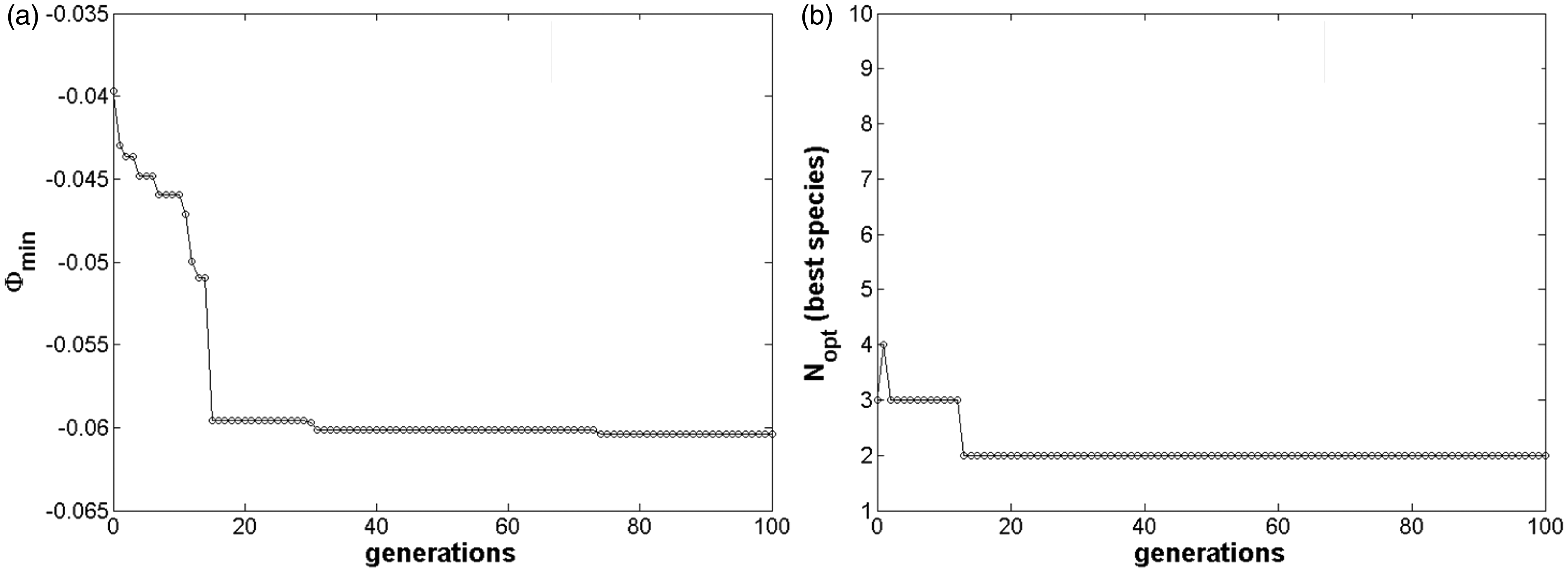
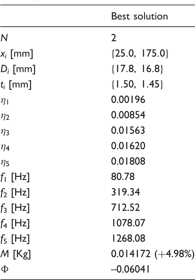
Figure 9 shows the best individual within the population (the best distribution of the patches over the plate for the present case), at the first and at the last generation. Again, according also with Figure 8(b), it can be noticed that the geometry (in terms of diameter and thickness), the positions and the number of patches change during the generations.
Best distribution of viscoelastic patches at the (a) initial and (b) final generation (optimum) for problem (29), Case 1(b).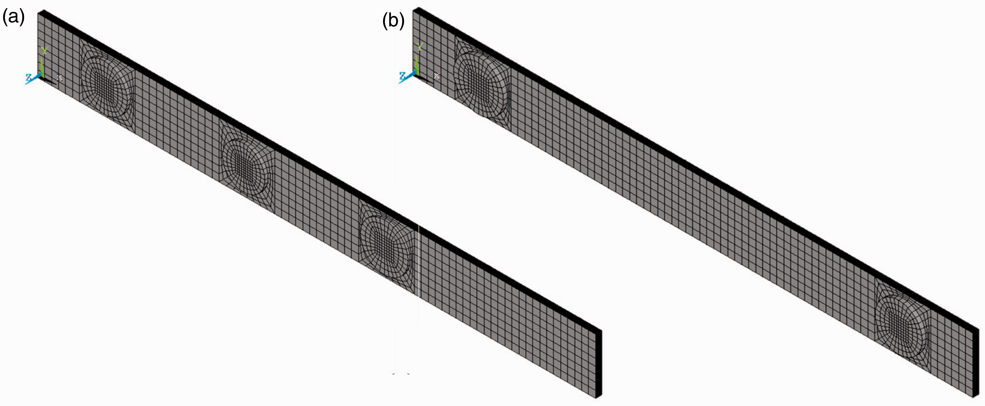
6.3. Example 2. General case
This is the most general case where the design of both the elastic and viscoelastic parts of the structure is realized simultaneously in order to maximize its damping capabilities. We recall that in this last example also the constitutive parameters of the laminate, i.e. its total thickness and the anisotropic polar parameters, are included among the design variables. The genotype of the individual is the one discussed in Section 3 and shown in Figure 3.
Due to the greater complexity of the optimization process in the present case, the population size and the maximum number of generations are increased up to
The best solution found by BIANCA is shown in Table 5. The optimal number of viscoelastic patches for the damping maximization for this last case is seven. The global constrained minimum was found after 111 generations, see Figure 10(a). Figure 10(b) shows the variation of the optimal number of viscoelastic patches along the generations: at the first generation the best species shows three patches bonded over the plate. Then, one can see that the best number of patches N varies between five and seven, and that the optimal value of N is reached after 42 generations. Thus, as in the previous examples, the convergence towards the best value of N and that of the objective function are independent, and the convergence towards the best species is faster than the convergence towards the best individual.
(a) Best values of the objective function and (b) optimal number of patches along generations for problem (29), Case 2. Best solution found using BIANCA for the optimization problem (29), Case 2.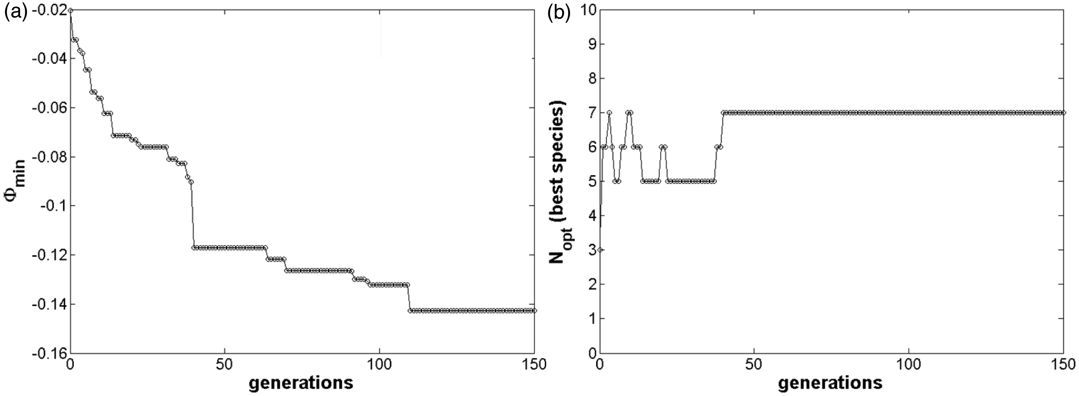
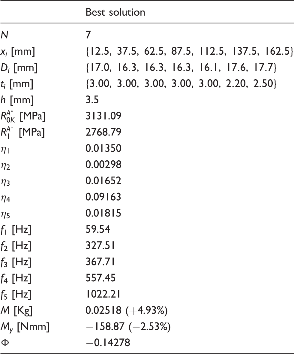
Figure 11 shows the optimal distribution of the patches over the plate for the present case, at the first and at the last generation. Once again, the sizes (diameter and thickness), the positions and the number of patches change during the generations.
Best distribution of viscoelastic patches at the (a) initial and (b) final generation (optimum) for problem (29), Case 2.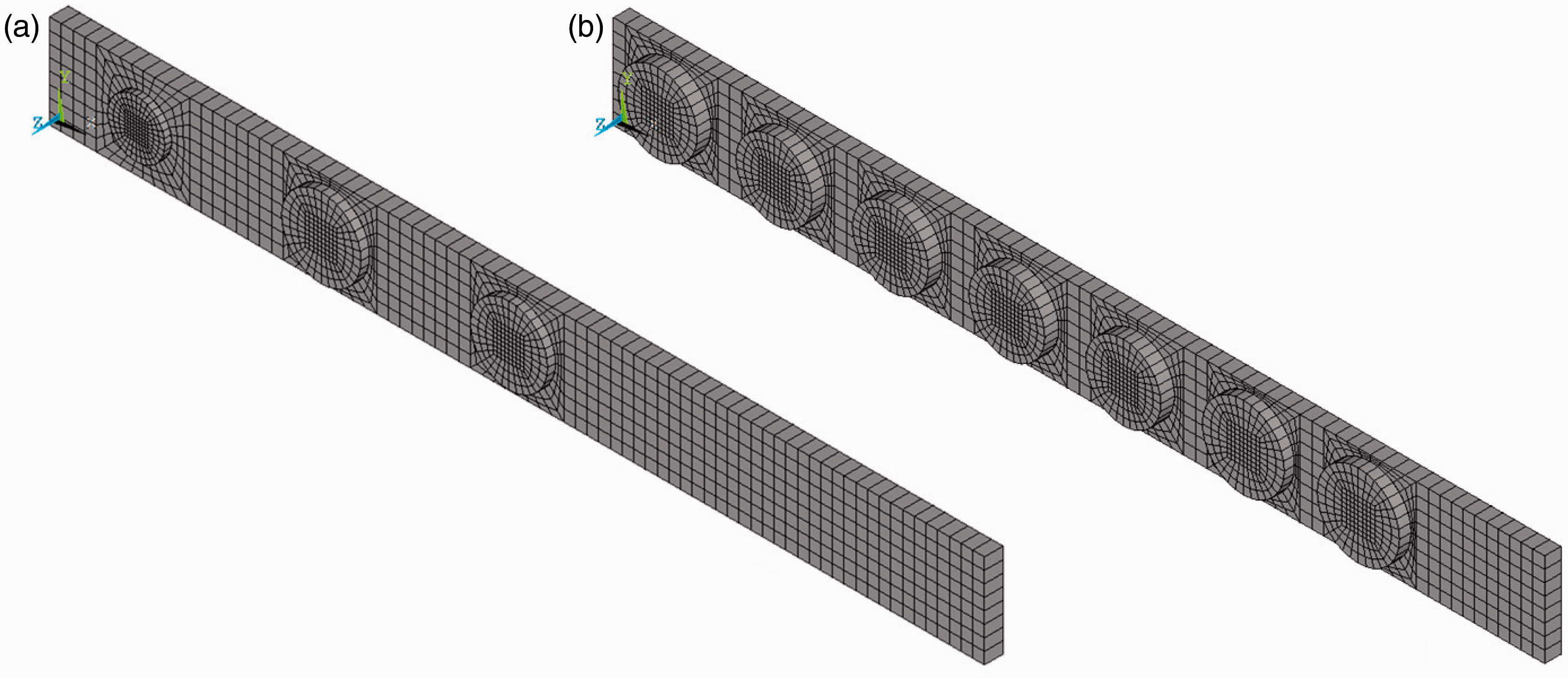
The first five non-rigid modes for the optimal configuration of the whole structure are shown in Figure 12. It can be noticed that we have different kinds of modes: the first, the third and the fifth mode are bending modes in the x– z-plane of the plate, whilst the second one is a bending mode in the x– y-plane of the plate and finally the fourth mode is a torsional mode around the x-axis. Of course, the optimal distribution of the viscoelastic material, i.e. the distribution of the rubber patches over the plate, along with the elastic properties of the composite plate are influenced by all the modes and the related damping mechanisms.
First five non-rigid modal deformed shapes of the whole structure for the optimal configuration, Case 2.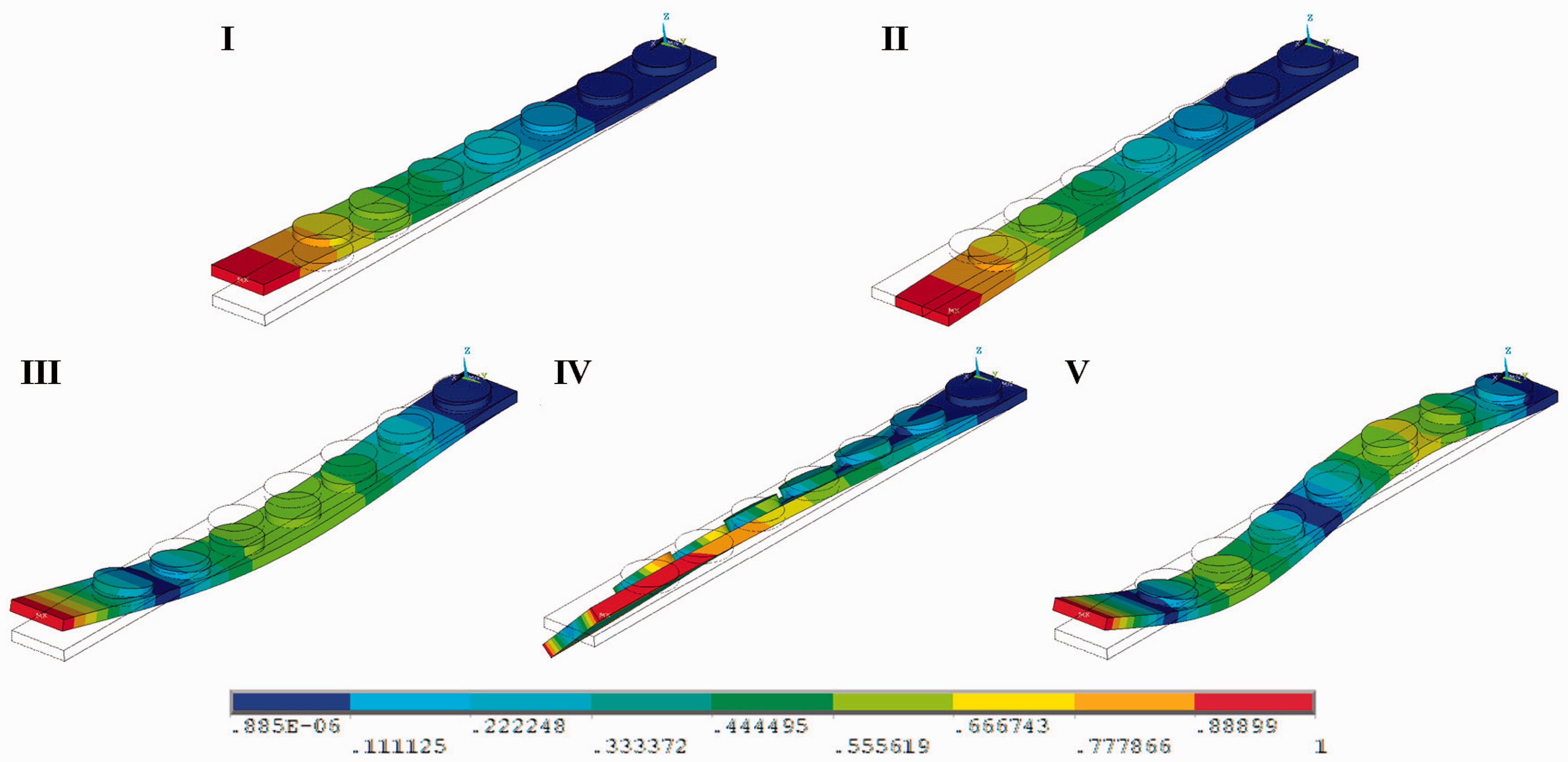
Considering that the value of the ply thickness is 0.125 mm, from Table 5 we can notice that the laminated plate is made of 28 plies (the total optimum thickness of the laminate is
Concerning the second-level problem, the design variables are the layers orientations, which can vary between
Table 6 shows the best stacking sequence found using BIANCA for the second-level problem. The residual in the last column is the value of the global objective function (a) First component of the homogenized stiffness tensors of the laminate and (b) best values of the objective function during iterations, Case 2. Case 2: best stacking sequences for the optimal solution.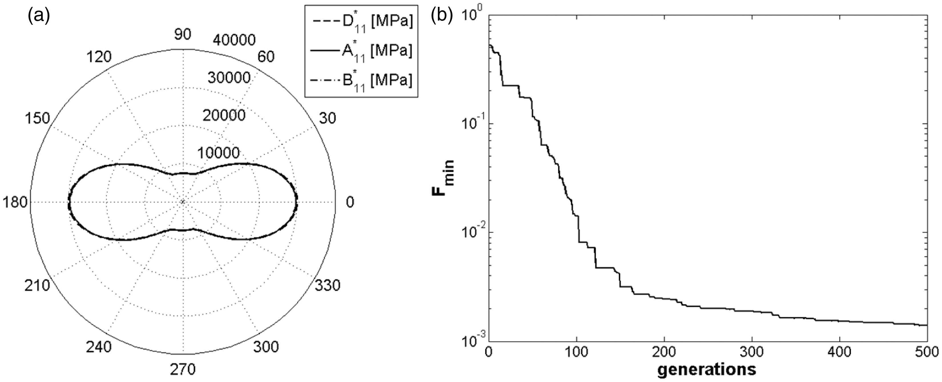
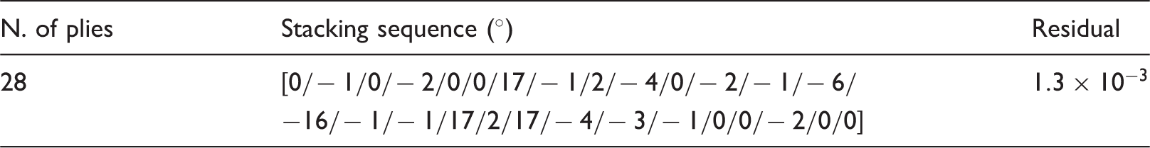
Figure 13(b) shows the variation of the best solution during iterations: the best solution is found after 470 generations.
6.4. Discussion of the results
Concerning the influence of the BCs of the model on the optimal distribution of the viscoelastic patches we can immediately see this effect by considering the results of the Cases 1(a) and 1(b) of the first example. In Case 1(a) the patches are placed near to the clamped root section of the plate, i.e. in the region where the strains are higher and, consequently, where the damping phenomenon linked to those strain components is stronger.
The same considerations can be done also for the distribution of the patches for Case 1(b): in this case the distribution is almost symmetric with respect to the values of the diameters, thicknesses and positions, see Table 4, coherently with the symmetric boundary conditions. As in Case 1(a), also in this second case the patches are placed in the regions where the plate is simply supported, i.e. where the strains are higher.
Figure 14(a) and (b) show the maximum strain components in the rubber patches with respect to Cases 1(a) and 1(b). It can be noticed that, when we consider bending modes in the x– z-plane (i.e. modes n. 1, 3 and 4 for Case 1(a) and modes n. 1, 3 and 5 for Case 1(b)), despite all the strain components involved in the damping phenomenon, the major contribution is due to the axial strain Maximum strain components in the viscoelastic patches for the optimized plate, (a) Case 1(a), (b) Case 1(b) and (c) Case 2.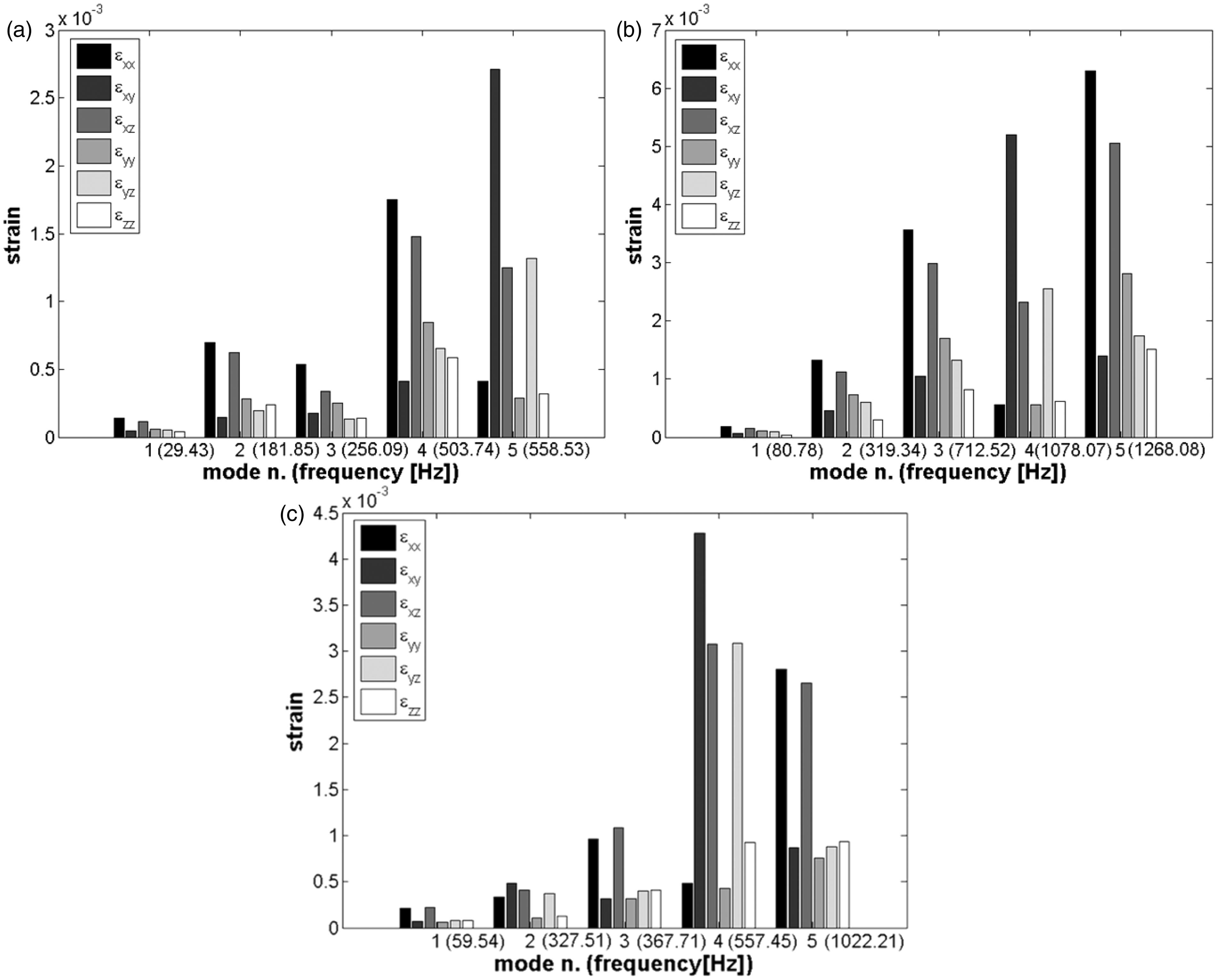
Concerning the second example, the simultaneous optimization of the viscoelastic and elastic properties of the structure allows to find better damping capabilities when compared to the first two cases. Only by considering the overall design of the structure one can hope to find a real global optimum configuration: for this last case, in fact, the damping capability of the structure (and, hence, the values of the modal loss factors) is practically doubled with respect to that of the first example. Thus, this last example demonstrates that the design of the “damping system” (the viscoelastic patches) must be integrated into the global design of the whole structure.
Figure 14(c) shows the maximum strain components in the rubber patches concerning the second example. The considerations made for the two sub-cases of the first example can be applied also to this second example. Nevertheless, we can notice that the major contribution to the damping phenomenon of this last case is due to the torsional mode, i.e. mode n. 4 in Figure 14(c): the value of the modal loss factor associated to that mode is nine times the value of the others loss factors, see Table 5. This means that the torsional mode of the plate has a strong effect on the final distribution of the patches over the plate, in terms of diameter, thickness and position.
As a conclusive remark, with respect to the second example, it can be noticed that, contrary to usual practice in the literature, we do not make any simplifying assumption on the laminate stacking sequence, which is completely free, neither do we use standard orientation angles for the elementary plies (like for instance
All the previous circumstances lead us to find a non-standard optimal solution which represents a real global optimum (in terms of the overall properties of the system) for the problem at hand.
7. Conclusions
The optimization procedure presented in this work is characterized by several points that make it an innovative, effective and general method for the design of hybrid modular structures. Our motivation was to create a general procedure for the optimization of modular systems, with the number of modules that belongs to the set of the design variables and without using special assumptions. The numerical method is, however, a fundamental part of the procedure because it is thanks to an appropriate numerical tool that we can simultaneously optimize the number of modules and their characteristics.
We briefly recall the features of the procedure:
No simplifying assumptions nor standard rules are used to design the laminated plate (this allows us to look for a true global minimum, hard to be obtained otherwise). The procedure is composed by two distinct but linked non-linear minimization problems: the first one is a constrained problem that uses a free-material approach in the design of the geometric and material properties of the modular composite structure via the polar representation of 2D elasticity; the second step is an unconstrained problem formulated to design a laminate able to realize the overall optimal mechanical properties designed in the first step. Quasi-homogeneous sequences are used; this allows us to write exact geometric bounds, valid for both the extension and bending behavior and to reduce the number of mechanical design variables in the first step. Bending orthotropy is really fulfilled, its type specified and the orthotropy direction directly managed, without using special sequences or orientations. The number of modules, i.e. the number of viscoelastic patches as well as the number of layers of the laminated plate, is directly optimized by the procedure. The optimization of the number of constitutive modules is possible thanks to a genetic approach which is able to select not only individuals, but also species: in practice, the algorithm determines automatically the optimal number of design variables. The mechanical characteristics of the laminated plate are represented by the polar formalism, that gives several advantages, namely to explicit elastic symmetries, elastic and geometric bounds, and to eliminate from the procedure redundant mechanical properties. The numerical computations are carried out by a special genetic algorithm, BIANCA, able to cross, simultaneously, species and individuals, to handle continuous and discrete valued variables during the same iterations and to effectively handle the constraints imposed to the problem. For the solution of the first-level problem, the code BIANCA is interfaced with an FE code, in order to numerically compute some mechanical quantities, namely the modal loss factors of the structure and the bending moment around the y-axis. The mathematical formulation of the second step problem allows us to take into account all the possible combinations of requirements on elastic properties; it is stated as the unconstrained minimization of a positive semi-definite function; being the minima of this function equal to zero, it is possible to know when a global minimum is attained.
To our best knowledge, this is the first time that the problem of maximizing the damping capabilities is formulated considering a discontinuous aperiodic distribution of viscoelastic material, namely by considering elastomer patches bonded over the structure which share the same form, but, at the same time, they can be characterized by different values of their constitutive geometrical parameters, i.e. diameter, thickness and position. Moreover, this is also the first time that the optimization problem is stated considering, in the form of constraint functions, the geometrical requirement on the position of the patches bonded over the plate. Thus, the key points of our strategy consist in determining what are: (a) the best number of rubber patches, (b) their best dimensions and positions over the structure, as well as (c) the best values of the thickness and of the polar parameters of the laminated plate which play an important role in the determination of the damping capability of the system.
The use of an evolutionary strategy along with the fact that the problem is stated in the most general case, leads us to find some non-conventional configurations, which show better damping properties when compared to the classical constrained layer treatments, namely classical hybrid elastomer/composite laminates.
Another point deserves attention: the passive solution consisting in patches bonded over composite plates is a good alternative with respect to introducing viscoelastic layers in sandwich plates, especially in terms of manufacturing because the patches can be deposited a posteriori on the plate surface. Nevertheless, we can see by the example treated in this paper, that such technology is relevant only if the structure is optimized a priori, i.e. if the simultaneous design of both elastic and viscoelastic properties of the structure is taken into account.
The proposed approach appears to be very flexible and applicable to various problems of structural engineering. Moreover, the procedure has a high level of versatility: more constraints could be easily added to the optimization problem, e.g. constraints on the strength, yielding or de-lamination of the laminate, without reducing the power and the robustness of the proposed approach.
Footnotes
Funding
The work of Marco Montemurro was supported by the National Research Fund (FNR) in Luxembourg through Aides à la Formation Recherche Grant (grant number PHD-09-139). He is grateful to the FNR for its support.