A two-degree-of-freedom floating vibration isolator (TDOFFVI) based on an anti-resonance mechanism is presented. This isolator has two tunable anti-resonance frequencies capable of attenuating vibrations at one or two frequency excitations simultaneously. A mathematical model of the TDOFFVI is developed. The force transmissibility and the anti-resonance frequencies in conjunction with design parameters are formulated and the optimal design of the TDOFFVI is given. A physical prototype of the TDOFFVI has been designed, built and tested. The experimental results validate the theoretical analysis and show that the TDOFFVI can perform effectively in vibration isolation.
When considering vibration isolation techniques, passive (or some semi-active controlled) isolators are cost effective and easy to maintain, which make them favorable in engineering applications. The performance of most passive isolation systems is confined to a certain bandwidth of vibration frequencies, where the lower frequency vibration isolations are of much concern. In order to improve the isolation performance in the low frequency range, Frahm (1911) presented a dynamic vibration absorber, which has the potential to isolate single frequency vibration completely. In recent times, there have also been many scholars studying this type of vibration isolator (Chatterjee, 2008; Gong et al., 2013; Shen et al., 2013). Quasi-zero-stiffness vibration isolation systems introduced recently (Ibrahim, 2008; Carrella et al., 2009; Zhou and Liu, 2010) possess the property of a high-static stiffness and low-dynamic stiffness. However, this type of isolator requires an exact match between the static load of mass and combined stiffness of systems, making their implementation more restrictive.
Similar to dynamic vibration absorbers, dynamic anti-resonance vibration isolators introduced in the aerospace industry (Goodwin, 1965; Flannelly, 1967; Rita et al., 1978; Halwes, 1980; Desjardins and Hooper, 1980; Braun, 1982) have no limitation on static load. This type of passive vibration isolator possesses an anti-resonance frequency, at which the inertial force counterbalances the fluctuations of the spring force. In order to isolate the lower frequency vibrations as the actual mass and the static stiffness of the system are constrained, leverage is often used to increase the effective mass. In practical applications, a fluid-type anti-resonance vibration isolator may offer a better solution since the hydraulic leverage has a compact arrangement and higher leverage ratio than a mechanical one. Different kinds of fluid-type anti-resonance vibration isolators have been reported previously. In order to adapt to the changes of excitation frequency, vibration isolators with tunable anti-resonance frequencies have also been designed. Hodgson and Duclos (1991), Jones and Downing (1993) and Smith and Stamps (1998) tuned the amplitude of the inertia force by varying the length of the fluid port. Plooy et al. (2005) designed adjustable pneumatic springs to tune the anti-resonance frequency of the system to be compliant with the external excitation frequency. Scarborough et al. (2012) presented a novel anti-resonance vibration isolator which couples a fluidic flexible matrix composite to an air-pressurized fluid port. By changing the air pressure, they were able to adjust the anti-resonance frequency. Liu et al. (2012) devised a single-degree-of-freedom floating vibration isolator (SDOFFVI) that can tune the added mass of flowing fluid by changing the immersion depth of the floating body.The above vibration isolators showed excellent isolation performance for a single frequency vibration. However, it is difficult for any of them to isolate vibrations including more than one frequency component. Yilmaz and Kikuchi (2006a,b) proposed a concept of anti-resonant vibration isolator which can isolate vibrations with multi-frequency components.Unfortunately, they did not develop physical devices for experimental verification.
Multi-frequency excitations are often encountered in machinery vibrations. For example, diesel engines of marine vessels may produce vibration noise at two major frequencies due to the utilization of a crank-slider mechanism. Isolation of machinery vibrations is important to improve acoustic stealth of marine vessels (Lou et al., 2005; Yu et al., 2007; Wen et al., 2009; Li et al., 2011; Zhou et al., 2012). Hence, it is desirable to develop a new type of anti-resonance vibration isolator that can suppress multi-frequency vibrations.
In this paper, a two-degree-of-freedom floating vibration isolator (TDOFFVI), which possesses two tunable anti-resonance frequencies, is proposed. The TDOFFVI is designed with a double-layer isolation configuration based on the anti-resonance mechanism. It is far more complicated than a SDOFFVI (Liu et al., 2012), because the interaction between the two coupled moving parts must be considered. Furthermore, the optimization of the design of the TDOFFVI becomes more complicated than that of the SDOFFVI since more design parameters are involved. In this paper, the mathematical model of the TDOFFVI is presented, the formula to calculate for the transmissibility force and the anti-resonance frequencies of the TDOFFVI are derived.Based on the theoretical analysis, the optimized design of the TDOFFVI is discussed and a comparison is made to the SDOFFVI. A series of experiments are carried out to validate the analytical results.
2. Theoretical analysis of the two-degree-of-freedom floating vibration isolator (TDOFFVI)
2.1. Description of the two-degree-of-freedom floating vibration isolator (TDOFFVI)
The TDOFFVI consists of a floating body, a smaller fluid container and a larger fluid container. The smaller fluid container is inside the larger one with support springs between, as well as fluid. A floating body is placed into the smaller fluid container supported by springs and fluid. A schematic diagram of the TDOFFVI is shown in Figure 1. The widths of the floating body, the smaller and the larger fluid containers, which cannot be shown in the two-dimensional plot, are approximately identical denoted by W, ignoring the wall thickness of the containers. Consider now that a mass is loaded on the floating body and the larger fluid container is rigidly mounted on a ground base. The excitation force provided by the load is directly applied to the mass, and is transmitted through the floating body to the smaller fluid container, then to the larger fluid container, and finally transmitted to the base.
The motion of the TDOFFVI is constrained in vertical direction with two moving parts of the floating body and the smaller fluid container. The equations of the motion for the floating body and the smaller fluid container are derived in this section.
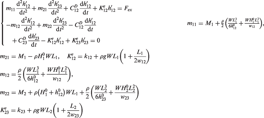
The spring forces acting on the floating body and the smaller fluid container are designated as and respectively, which can be calculated by the following formula
where is the stiffness of the springs between floating body and smaller fluid container, the stiffness of the springs between the smaller fluid container and the larger fluid container, the values of at the equilibrium respectively.
The dynamic fluid pressure distribution has to be determined before calculating the fluid forces acting on the floating body and the smaller fluid container. The two regions are considered: (1) the fluid between the smaller fluid container and the larger fluid container, (2) the fluid between floating body and the smaller fluid container.
As the pressure of fluid between the smaller fluid container and the larger fluid container is calculated, the inertial coordinate system fixed on the base (see in Figure 1) is employed. The symmetry of the structure allows the study to only focus on the region for . Under the condition of , the pressure and the velocity of the fluid in the horizontal channel between the smaller fluid container and the larger fluid container can be approximately expressed as the function of x and t. Ignoring the viscosity of the fluid, the momentum equation of the fluid in the horizontal channel is given as
where ρ is the density of the fluid, and the horizontal velocity and dynamic pressure of the fluid in the horizontal channel between the smaller fluid container and the larger fluid container respectively. For incompressible fluid, the continuity condition requires
where is the velocity of the smaller fluid container. Substituting (4) into (3), gives the expression for as
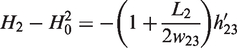
In order to determine the value of , the pressure of the fluid in the vertical channel between the smaller fluid container and the larger fluid container is discussed. At the free surface (), dynamic pressure of fluid equals zero. If and the viscosity of the fluid is ignorable, the momentum equation of the fluid in the vertical channel between the smaller fluid container and the larger fluid container is written as
where is the vertical velocity of the fluid in the vertical channel between the smaller fluid container and the larger fluid container, the dynamic pressure of the fluid at , the value of at the equilibrium. The value of is given by the continuity condition that leads to the values of and
For the region of the fluid, the point at and the point at can be regarded as proximately the same point, the pressures should be equal, i.e. , and thus by (5), (6), (7) and (8) the expression for can be obtained as
Substituting (9) into (5), gives
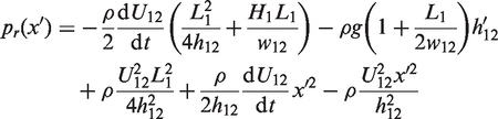
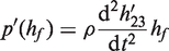
The dynamic pressure of fluid between the floating body and the smaller fluid container can be calculated in the coordinate system fixed on the smaller fluid container (see in Figure 1). Since the is not an inertial coordinate system, is written as
Where pr is the dynamic pressure obtained by assuming that is an inertial coordinate system, and that is the pressure induced by the acceleration of the smaller fluid container. The expression for pr is similar to the expression for and determined by
where is the velocity of the floating body relative to the smaller fluid container. The value of can be calculated by
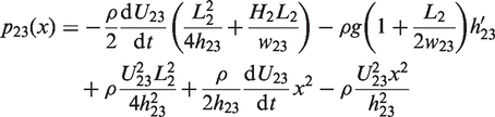
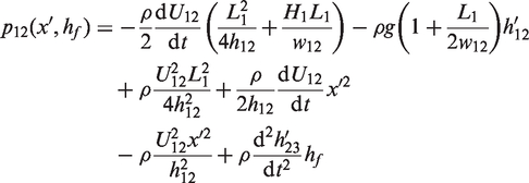
where hf is the vertical distance of a point in the fluid from the free surface. Substituting (12) and (13) into (11), gives the expression for the pressure
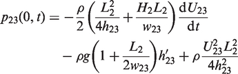
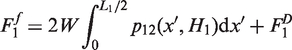
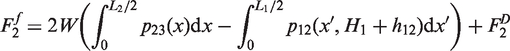
Under the condition of , the dynamic forces acting on the floating body and the smaller fluid container by the fluid are calculated by the following formulae respectively
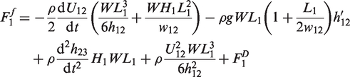
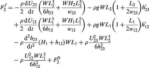
where is the added terms if we consider the viscosity of the fluid. Substituting (10) and (14) into (15) and (16), gives
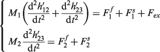
The equations of motion of the floating body and the smaller fluid container are thus given by
where M1, M2 are the mass of floating body and the smaller fluid container respectively. Substituting (1), (2), (17), and (18) into (19) and considering small amplitude vibrations, gives the equations of motion as
where are the values of at the equilibrium respectively, and are the damping coefficients. The values of and are related to the fluid viscosity. As the fluid viscosity is ignored, . Considering nonlinear problems, and must be the function of the vibration frequency and velocity. In this paper, linear problems are studied, so , are assumed to be constant.
2.3. Force transmissibility of the two-degree-of-freedom floating vibration isolator (TDOFFVI)
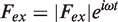
Force transmissibility is used to assess the efficiency of vibration isolation. An excitation force can be expressed in the complex form
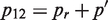
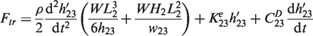
The forces transferred to the base through the isolation system () then consist of the forces acting on the larger fluid container by the fluid and springs, which can be expressed as
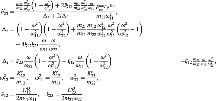
Substituting the excitation force (21) into equation (20), leads to the complex expression of dynamic response in the steady state
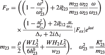
where is one of the anti-resonance frequencies of the TDOFFVI corresponding to the balance of the inertia force induced by the moving fluid and spring force between the floating body and the smaller fluid container, and are the non-dimensional damping coefficients. Substituting (23) into (22), gives the complex expression of the transmitted force as
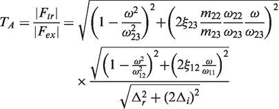
where is the other anti-resonance frequency of the TDOFFVI corresponding to the balance of inertia force induced by the moving fluid and spring force between the smaller fluid container and the larger fluid container. The force transmissibility of the isolation system is defined as
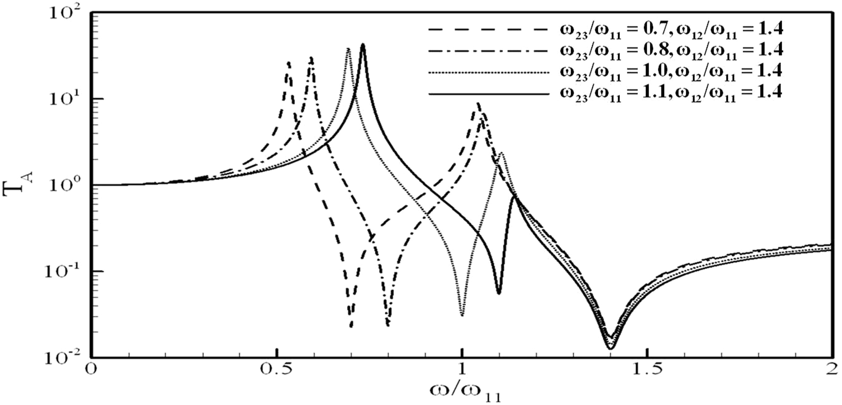
From the force transmissibility, the TDOFFVI has two anti-resonance frequencies ( and ) with natural frequencies that are the most important factors to affect the force transmissibility. According to (25), the force transmissibility can tend to zero as the excitation frequencies are close to the anti-resonance frequencies in the absence of damping (ignoring the fluid viscosity). Note that the anti-resonance frequencies of the TDOFFVI can be adjusted by changing the values of , which stand for height levels of fluid filled in the two containers at the equilibrium state. There are also two natural frequencies of the TDOFFVI, which can be obtained by letting . The variation of the TDOFFVI force transmissibility with excitation frequencies for different values of and is shown in Figure 2.
Variations of the two-degree-of-freedom floating vibration isolator (TDOFFVI) force transmissibility with excitation frequency, where .
The frequencies at the two minimum values of the force transmissibility exactly correspond to the two anti-resonance frequencies of the TDOFFVI. The two maximum values of the force transmissibility correspond to the two natural frequencies of the TDOFFVI. The fluid levels of can be adjusted in the containers to tune the two anti-resonance frequencies of the TDOFFVI as required. When the two anti-resonance frequencies are tuned to the two excitation frequencies respectively, the force transmissibility can be greatly reduced. Apart from adjusting the fluid levels, the gap parameters can also be used to tune the anti-resonance frequencies. Since the gap parameters can be designed in desirable small dimensions, very low anti-resonance frequencies of the TDOFFVI can be obtained. Thus the TDOFFVI can be used to isolate vibrations at two excitation frequencies simultaneously.
3. Design optimization of the two-degree-of-freedom floating vibration isolator (TDOFFVI)
A desirable vibration isolator should be one that possesses a low force transmissibility with small static deflection and little mass. The TDOFFVI can perform highly effective vibration attenuation when the anti-resonance frequencies exactly match with the excitation frequencies. To achieve this condition, it requires an optimal design of the design variables for the best performance.
The static deflection of the TDOFFVI is determined by the effective stiffness
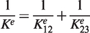
where Fs is the static force acting on the floating body, the static displacement of the floating body. The effective stiffness of the TDOFFVI can be obtained by
The mass of the TDOFFVI is the sum of the mass of the floating body and the mass of the smaller fluid container, approximately
It is known from (25) that the force transmissibility of TDOFFVI depends on , , , . In order to isolate lower frequency vibration, the design of is adopted, which gives . As the weight of the floating body is mainly balanced by springs, . It is known from (20) that . The value of can be expressed as . Thus the force transmissibility of TDOFFVI can be expressed by the function of
Choosing and as characteristic variables, (29) can be written as the following dimensionless form by the Buckingham π theorem
where is defined as
The effects of , , and on the isolation performance of the TDOFFVI are discussed in this paper.
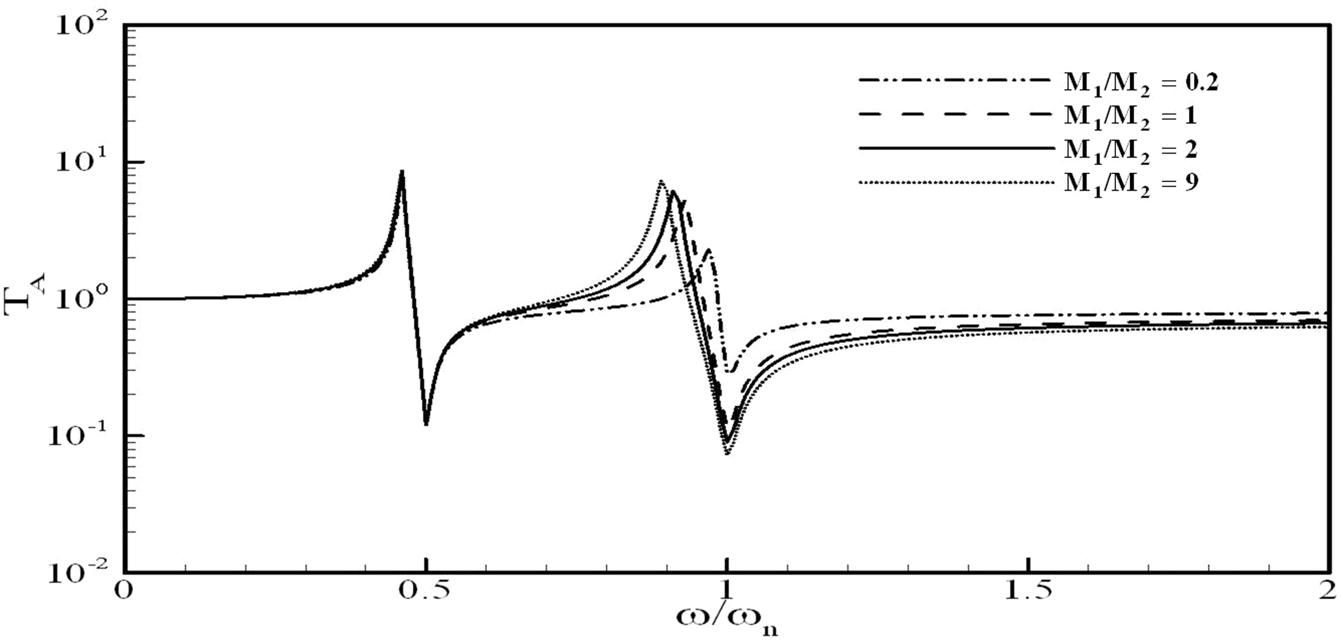
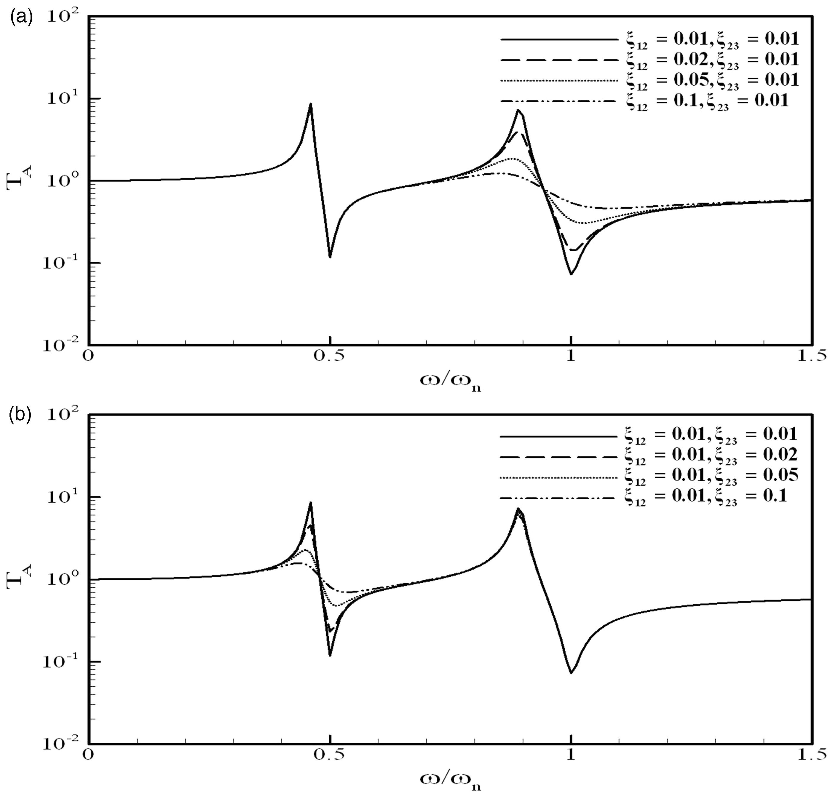
As other design variables are fixed, the variation of the TDOFFVI force transmissibility with dimensionless excitation frequency for different values of is shown in Figure 3. It is shown that the ratio of mainly affects the values of the second peak and trough (or valley) that correspond to the resonance and anti-resonance frequency of the floating body. It implies that the selection of the ratio of hardly influences the first resonance and the first anti-resonance frequency which is related to the small container.
Variations of the two-degree-of-freedom floating vibration isolator (TDOFFVI) force transmissibility with dimensionless excitation frequency for different values of , .
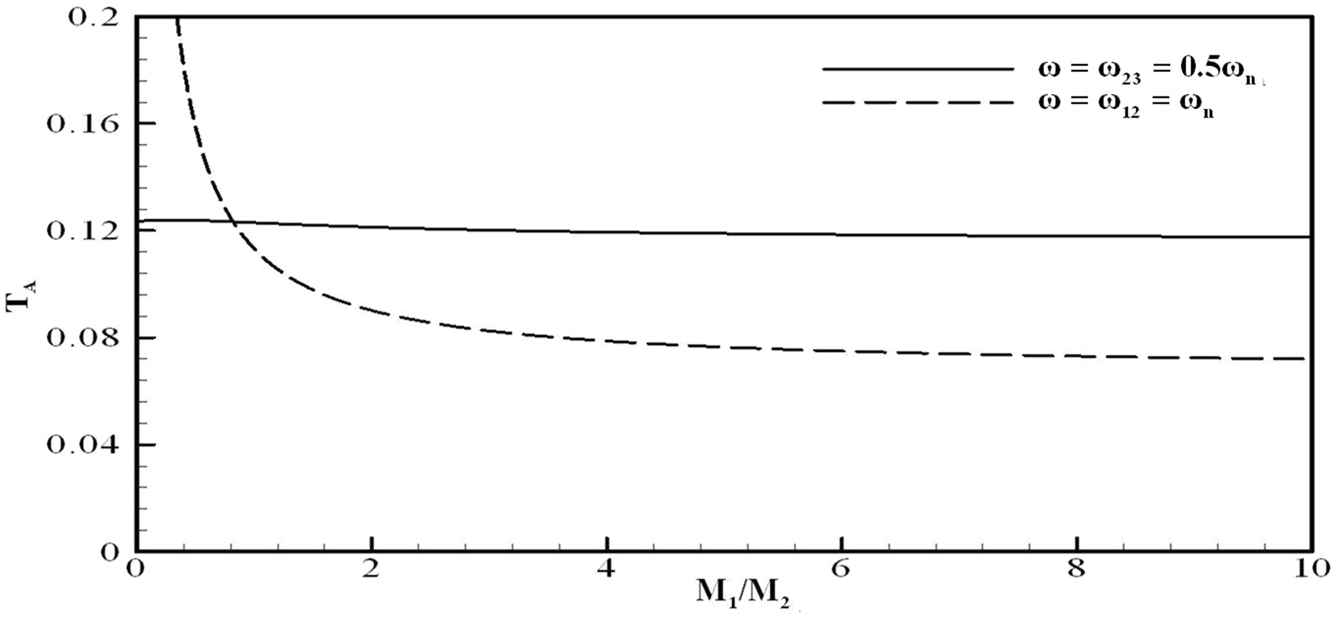
Figure 4 plots the variation of force transmissibility at the first anti-resonance frequency () and the second anti-resonance frequency () against . This plot indicates that the force transmissibility at the second anti-resonance frequency () decreases sharply and then tends to flatten out with the increase of , while the change of does not overly affect the force transmissibility at the first anti-resonance frequency . The reason for this could be that at , the excitation force is mainly balanced by the inertia force due to the acceleration of the floating body. As increases, the acceleration amplitude of the floating body can decrease, which leads to the decrease of force transmissibility. At , the excitation force is mainly balanced by the inertia force of the floating body and the smaller fluid container. The value of does not affect the total mass of the floating body and the smaller fluid container, so the force transmissibility remains almost constant as varies. Thus, the ratio of can be designed to control the force transmissibility of the TDOFFVI around the second anti-resonance frequency ().
Variations of the two-degree-of-freedom floating vibration isolator (TDOFFVI) force transmissibility at anti-resonance frequency with the change of the ratio , with .
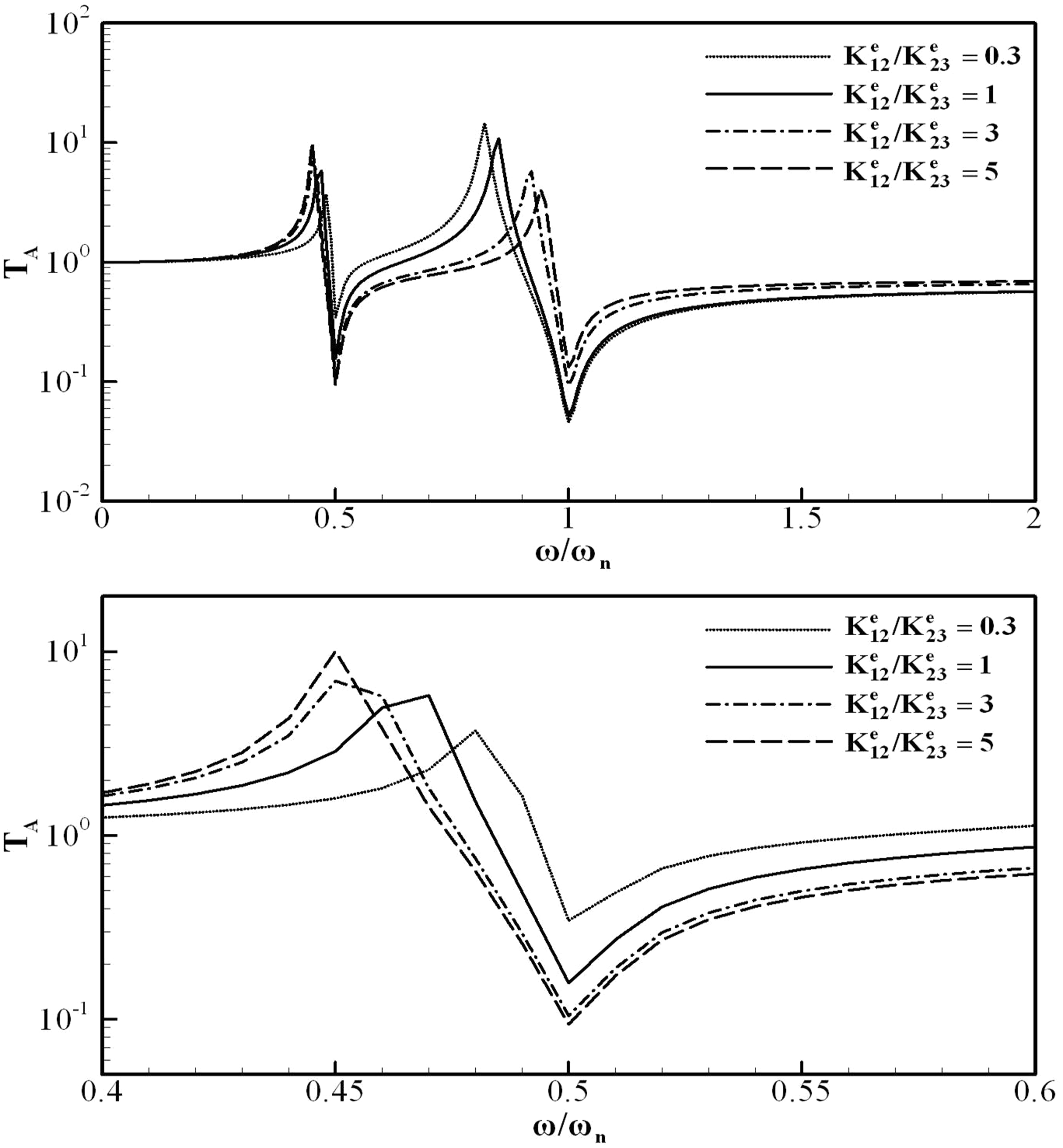
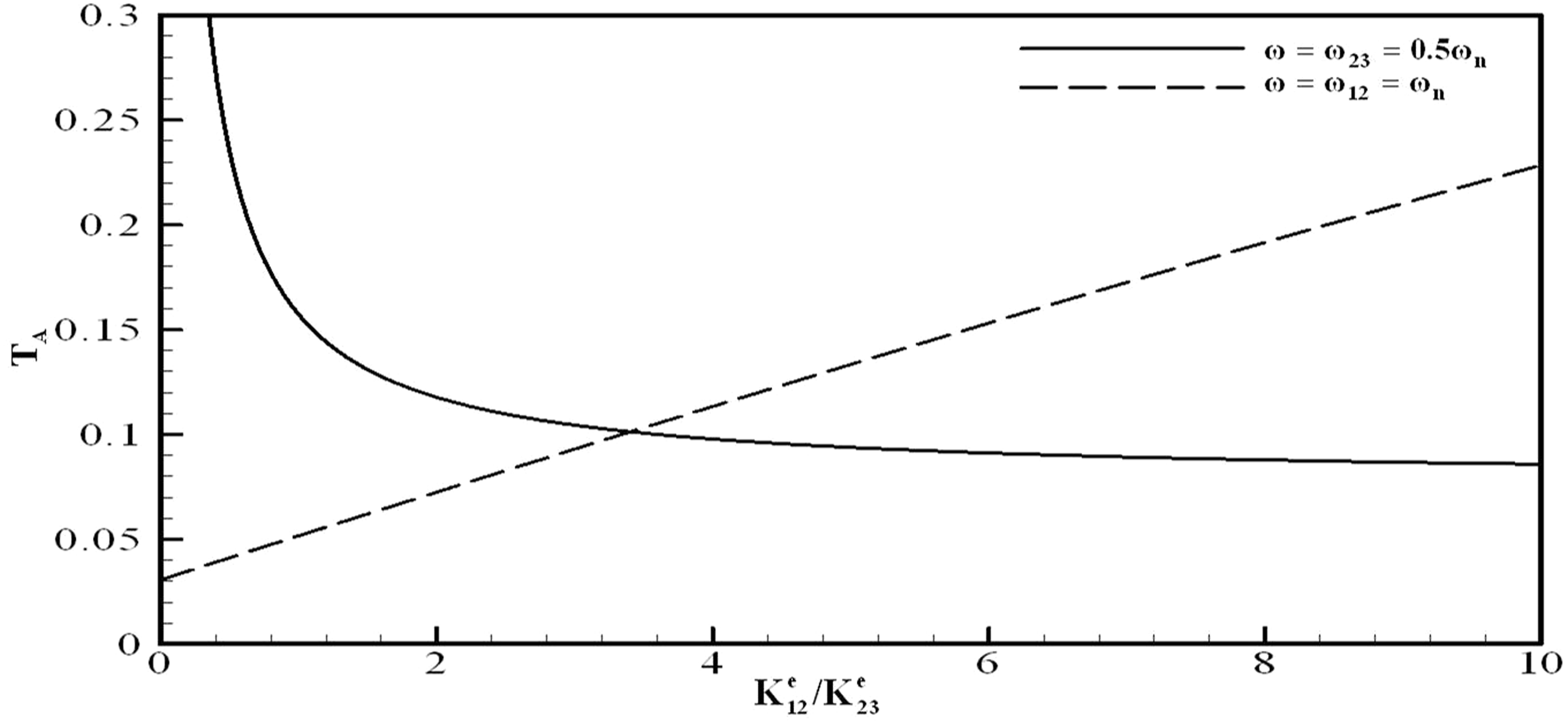
The effect of the different stiffness ratios of on the force transmissibility of the TDOFFVI against is shown in Figure 5. It shows that the ratio of can clearly alter the resonance peaks but it does not shift the anti-resonance frequencies. Figure 6 plots the variation of force transmissibility at the first anti-resonance frequency () and the second anti-resonance frequency () with . The broken line shows that increasing can linearly increase the force transmissibility at the second anti-resonance frequency, but sharply and nonlinearly decrease it at the first anti-resonance frequency. It reveals a useful clue that the value of at which the two curves intersect may be adopted for an unbiased design in terms of transmissibility.
Variations of the two-degree-of-freedom floating vibration isolator (TDOFFVI) force transmissibility with dimensionless excitation frequency for different values of , when .
Variations of the two-degree-of-freedom floating vibration isolator (TDOFFVI) force transmissibility at anti-resonance frequency with , when .
The behavior of the TDOFFVI is also affected by two damping coefficients and , which mainly depend on the viscous dissipation of the fluid in between the containers. Figure 7 shows the variation of force transmissibility with for different values of and . It indicates that and affect the force transmissibility at and respectively. Decreasing the value of can decrease the force transmissibility at , while it has little effect on the force transmissibility at . Decreasing the value of can decrease the force transmissibility only at . The effect of the damping coefficients and on the force transmissibility is rather localized and independent of each other. Due to the values of and being reduced by decreasing the fluid viscous dissipation, using the fluid with small viscosity is beneficial to obtain lower force transmissibility at anti-resonance frequency.
Variations of the two-degree-of-freedom floating vibration isolator (TDOFFVI) force transmissibility with dimensionless excitation frequency for different values of and , when , .
4. Comparison of the two-degree-of-freedom floating vibration isolator (TDOFFVI) with the single-degree-of-freedom floating vibration isolator (SDOFFVI)
In order to obtain a better understanding of the TDOFFVI performance, the force transmissibility for one- and two-frequency vibration is estimated and compared with that of the SDOFFVI (Liu et al., 2012) under the identical conditions of the effective stiffness, mass and damping coefficient of the two systems. The effective stiffness and mass of the TDOFFVI have been discussed in Section 3. The effective stiffness of the SDOFFVI is the stiffness of springs between the floating body and fluid container, and the mass of the SDOFFVI equals the floating body mass approximately. Both and are equal to the damping coefficient of the SDOFFVI, which is denoted by ξ.
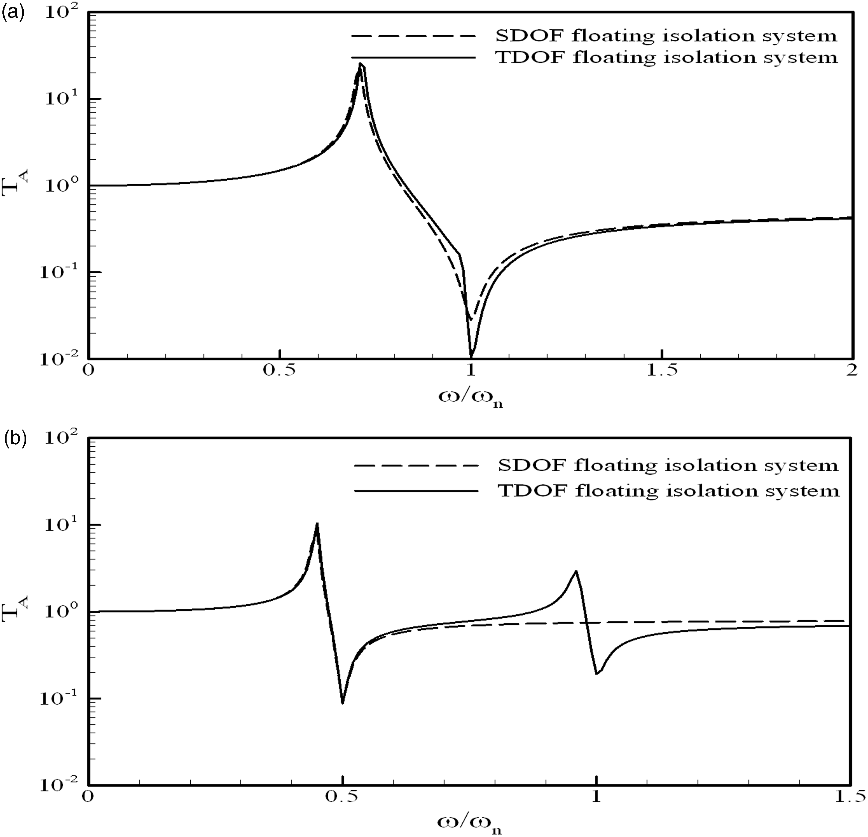
As the TDOFFVI is used to tackle a single-frequency vibration, the two anti-resonance frequencies of the TDOFFVI can be adjusted to be identical simultaneously. As the two anti-resonance frequencies of the TDOFFVI coincide, the force transmissibility at the anti-resonance frequency can be reduced even lower. Figure 8(a) shows the curve of the force transmissibility of the TDOFFVI and the SDOFFVI versus excitation frequency under the condition of , where is the anti-resonance frequency of the SDOFFVI. It shows that the force transmissibility at anti-resonance frequency of the TDOFFVI is much lower than that of the SDOFFVI. The reason for this excellent performance is as follows. The amplitude of the force of the floating body transmitted to the smaller fluid container can be calculated by
where is the force transmissibility from the floating body to the smaller fluid container.
The plot of the force transmissibility of the two-degree-of-freedom floating vibration isolator (TDOFFVI) and single-degree-of-freedom floating vibration isolator (SDOFFVI) versus excitation frequency, , (a) , (b) , .
Then this force is transmitted from the smaller container to larger fluid container (and then the base) via springs and fluid, the amplitude of the transmitted force can be calculated by
where is the force transmissibility from the smaller fluid container to the base. According to (30) and (31), the total force transmissibility of the TDOFFVI can be expressed by
If , the values of and become equal () where the value of equals the force transmissibility of the SDOFFVI approximately. Thus the force transmissibility of the TDOFFVI is much lower than of the SDOFFVI as .
For general cases, the TDOFFVI can cope with two excitation frequencies. The curve of the force transmissibility of the TDOFFVI and SDOFFVI versus excitation frequency under the condition of is depicted in Figure 8(b). At , the force transmissibility of the TDOFFVI is almost the same as that of the SDOFFVI, while at , the force transmissibility of the TDOFFVI is much lower than that of SDOFFVI. Machinery vibrations usually possess multi-frequency features observed from line spectra in a frequency domain. The design of the TDOFFVI thus serves as a simple model to cope with multi-frequency vibrations with excellent isolation performance.
5. Experiment verifications
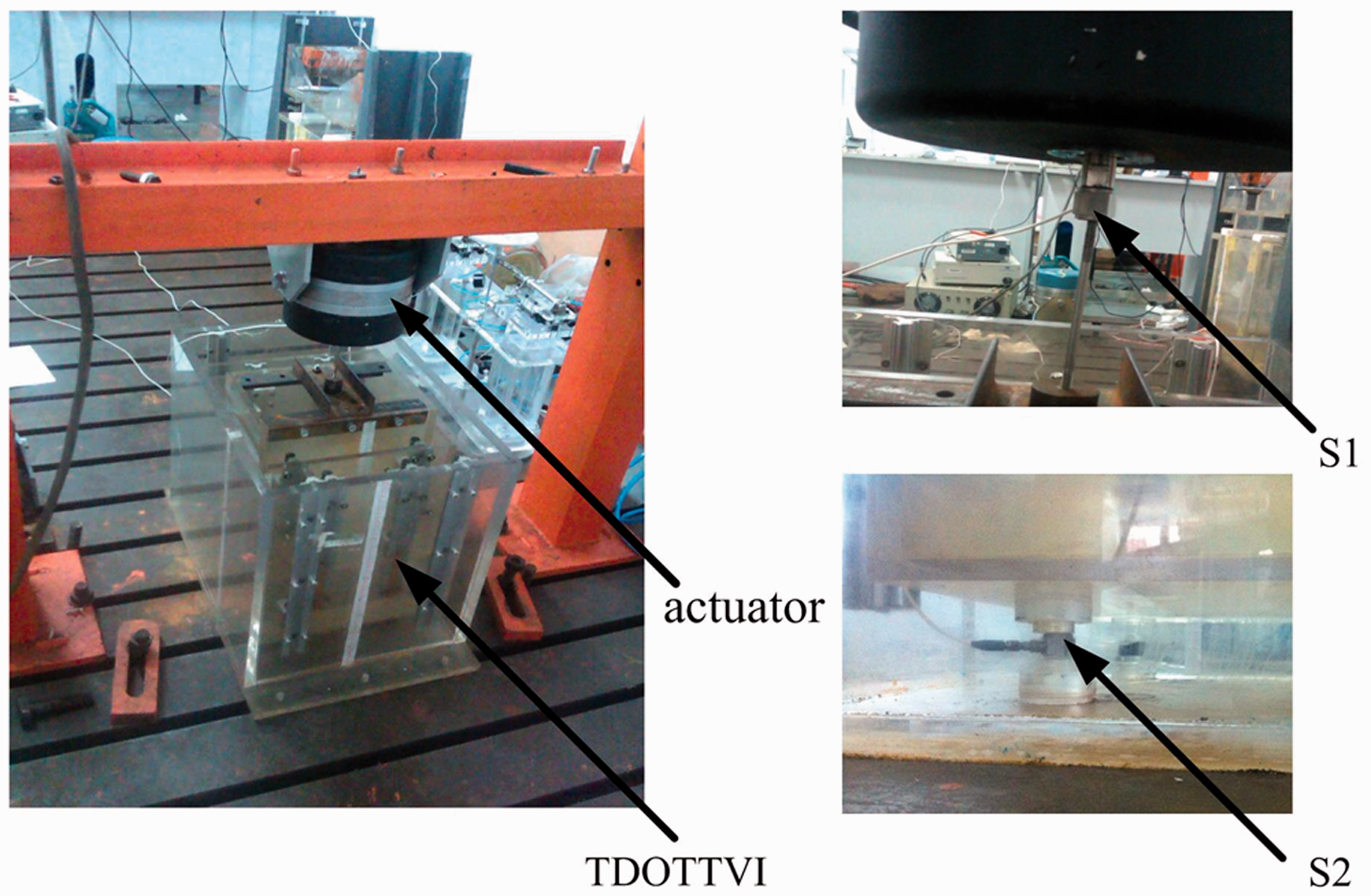
A physical prototype of the vibration isolator (see in Figure 9) was designed and built for an experimental study. The floating body, smaller fluid container and larger fluid container of the isolator are made of perspex. The structure dimensions and design parameters of the TDOFFVI are given in Table 1. A force sensor (denoted as S1) was mounted in between the actuator and the floating body to measure the amplitude of the excitation force . The whole isolation system is supported by a force sensor (denoted as S2) and three perspex cylinders which have the same size as the force sensor S2. The same type force sensors (PCB 208C02, PCB Group Inc.) are used as S1 and S2. The four support points on the base are symmetrically distributed at the four corners of the TDOFFVI so that the force transmitted from each support can be regarded as being the same. Therefore, the total transmitted force from the TDOFFVI to the rigid base is four times of the force measured by the force sensor S2.
Prototype of the two-degree-of-freedom floating vibration isolator (TDOFFVI) and the force sensors used in experiments.
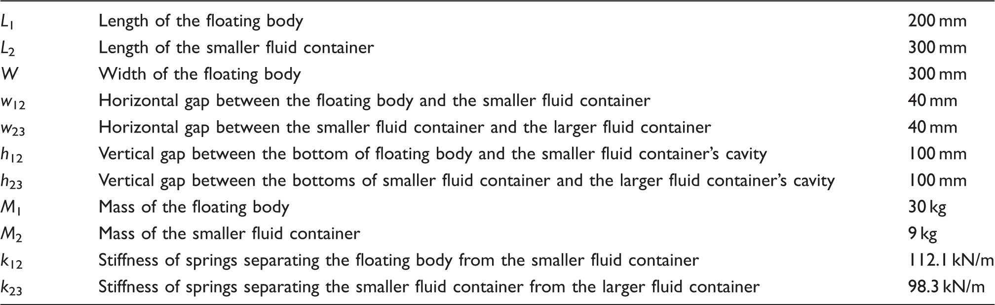
The main dimensions and parameters of the two-degree-of-freedom floating vibration isolator.
L1
Length of the floating body
200 mm
L2
Length of the smaller fluid container
300 mm
W
Width of the floating body
300 mm
w12
Horizontal gap between the floating body and the smaller fluid container
40 mm
w23
Horizontal gap between the smaller fluid container and the larger fluid container
40 mm
h12
Vertical gap between the bottom of floating body and the smaller fluid container’s cavity
100 mm
h23
Vertical gap between the bottoms of smaller fluid container and the larger fluid container’s cavity
100 mm
M1
Mass of the floating body
30 kg
M2
Mass of the smaller fluid container
9 kg
k12
Stiffness of springs separating the floating body from the smaller fluid container
112.1 kN/m
k23
Stiffness of springs separating the smaller fluid container from the larger fluid container
98.3 kN/m
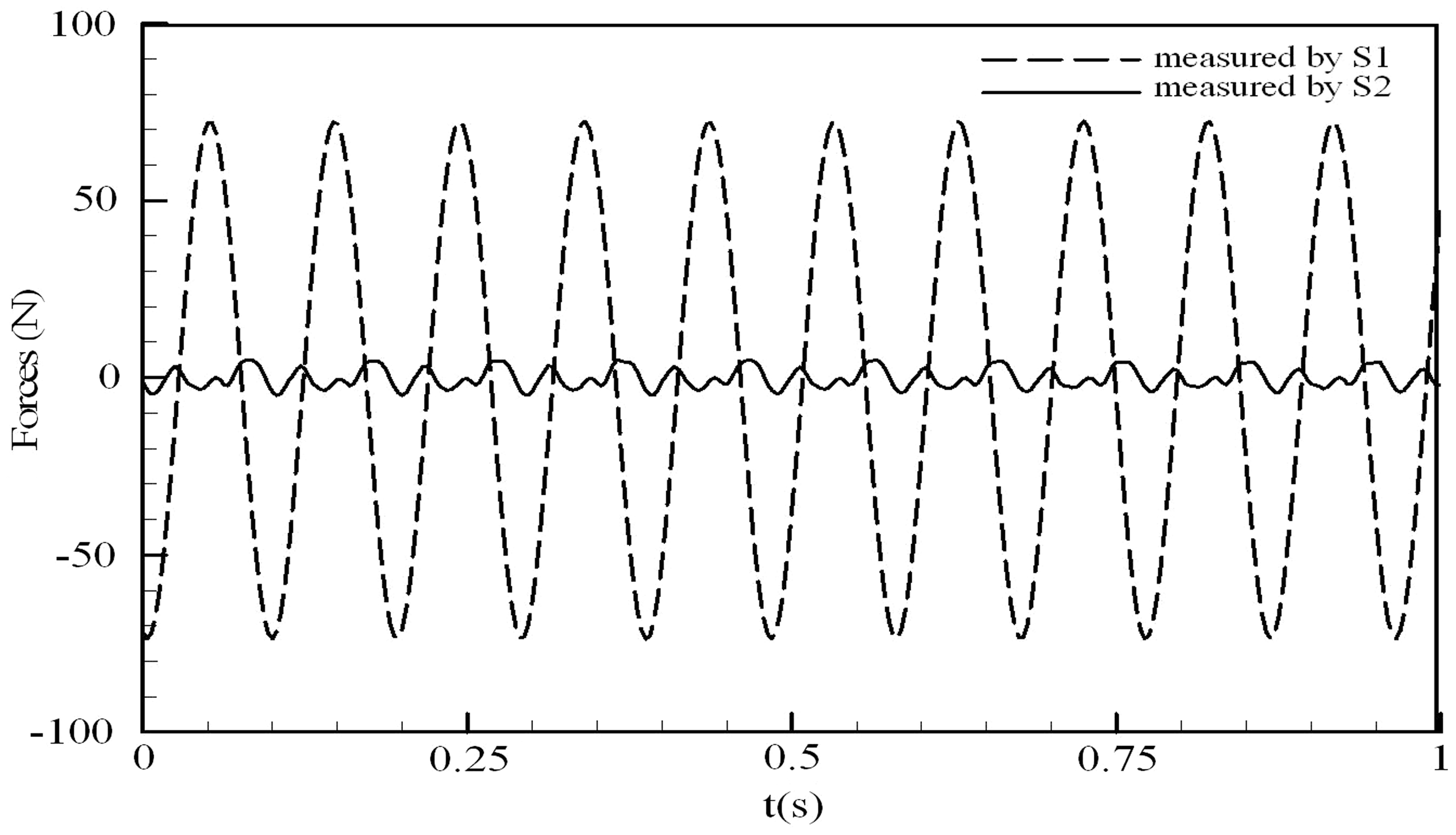
The floating body was harmonically excited by the actuator (HEV-200, Nanjing University of Aeronautics and Astronautics) within a frequency range from 0.2 to 50 Hz. The MI-7008 data acquisition and analysis system (Econ Technologies Co. Ltd.) was used to collect signals produced by force sensors S1 and S2. A 160 dB/Oct digital filter was integrated in MI-7008 system. In the experiments, the cut off frequency was set to be 50 Hz. Figure 10 shows an experimental record where the excitation force is 66 N and the excitation frequency is 10.3 Hz which is regarded as a fundamental frequency. Two anti-resonances of the TDOFFVI were adjusted to 6.3 Hz and 10.8 Hz respectively. The time history of the forces measured by S1 (excitation force) and S2 (transmitted force on the base), which are denoted as FS1 (t) and FS2 (t) respectively, were shown in Figure 10. It is seen that the force transmitted to the base is much smaller than the excitation force.
The time history of the excitation force measured by sensor S1 and the transmitted force to the base measured by sensor S2; the excitation frequency is 10.3 Hz, the excitation amplitude is 66 N.
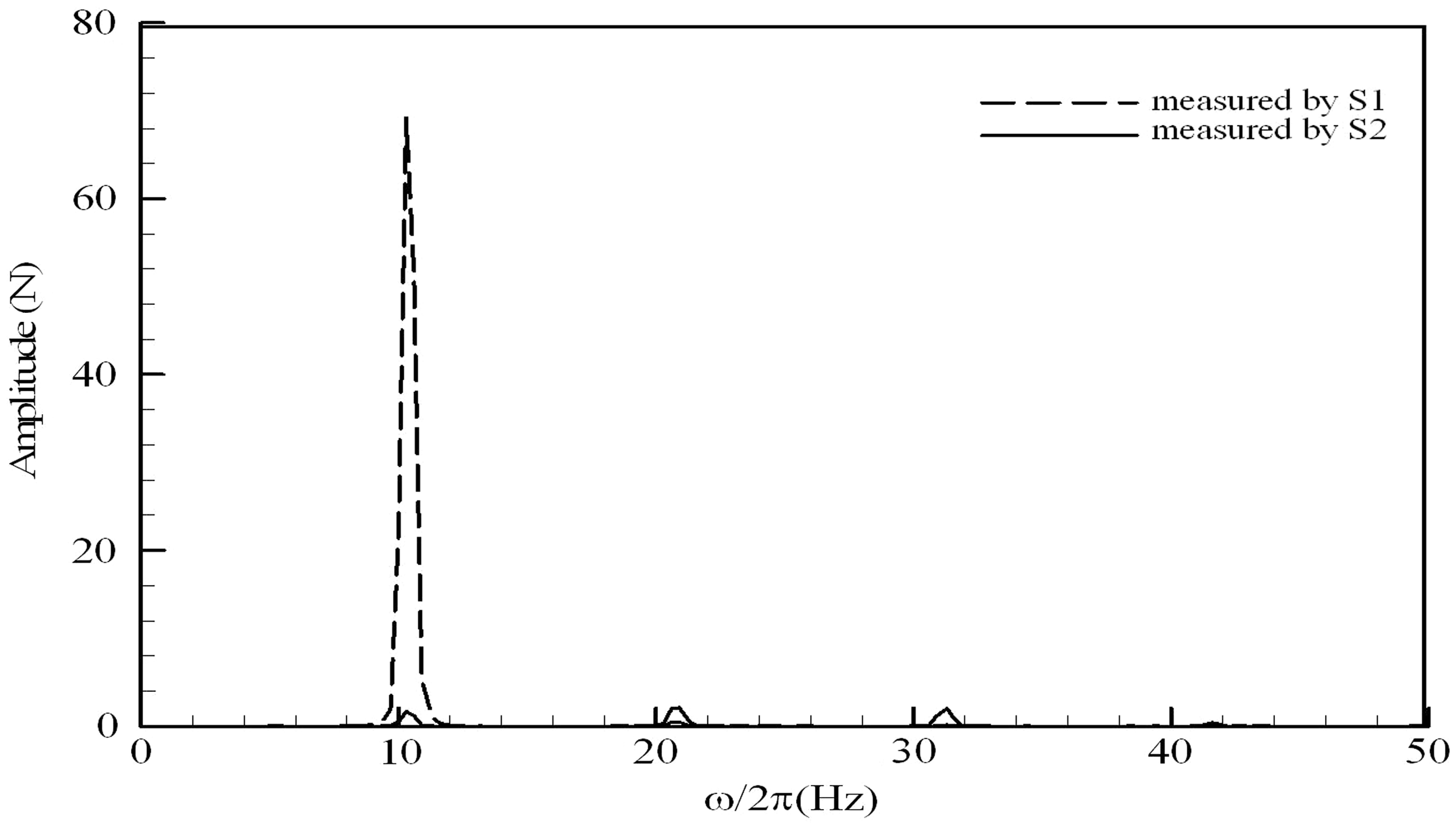
The line spectra of the excitation force measured by sensor S1 and the transmitted force to the base measured by sensor S2, the excitation frequency is 10.3 Hz, the excitation force amplitude is 66 N.
The frequency spectrum of FS2 (t) (see in Figure 11) is obtained by performing a fast Fourier transform (FFT). The spikes of line spectra observed at the multiple of the excitation frequency indicate the existence of higher frequency oscillations for the TDOFFVI. It is probably induced by fluid fluctuations in between the two containers or the nonlinear effects. In this paper, the authors focused on the force transmissibility at excitation frequency, and the amplitude of fundamental vibration of FS2 (t) (denoted by AS2) was used to calculate the force transmissibility
where is the amplitude of excitation force. It can be seen that the transmitted force at excitation frequency is reduced significantly as the excitation frequency approaches one of the anti-resonances of the TDOFFVI.
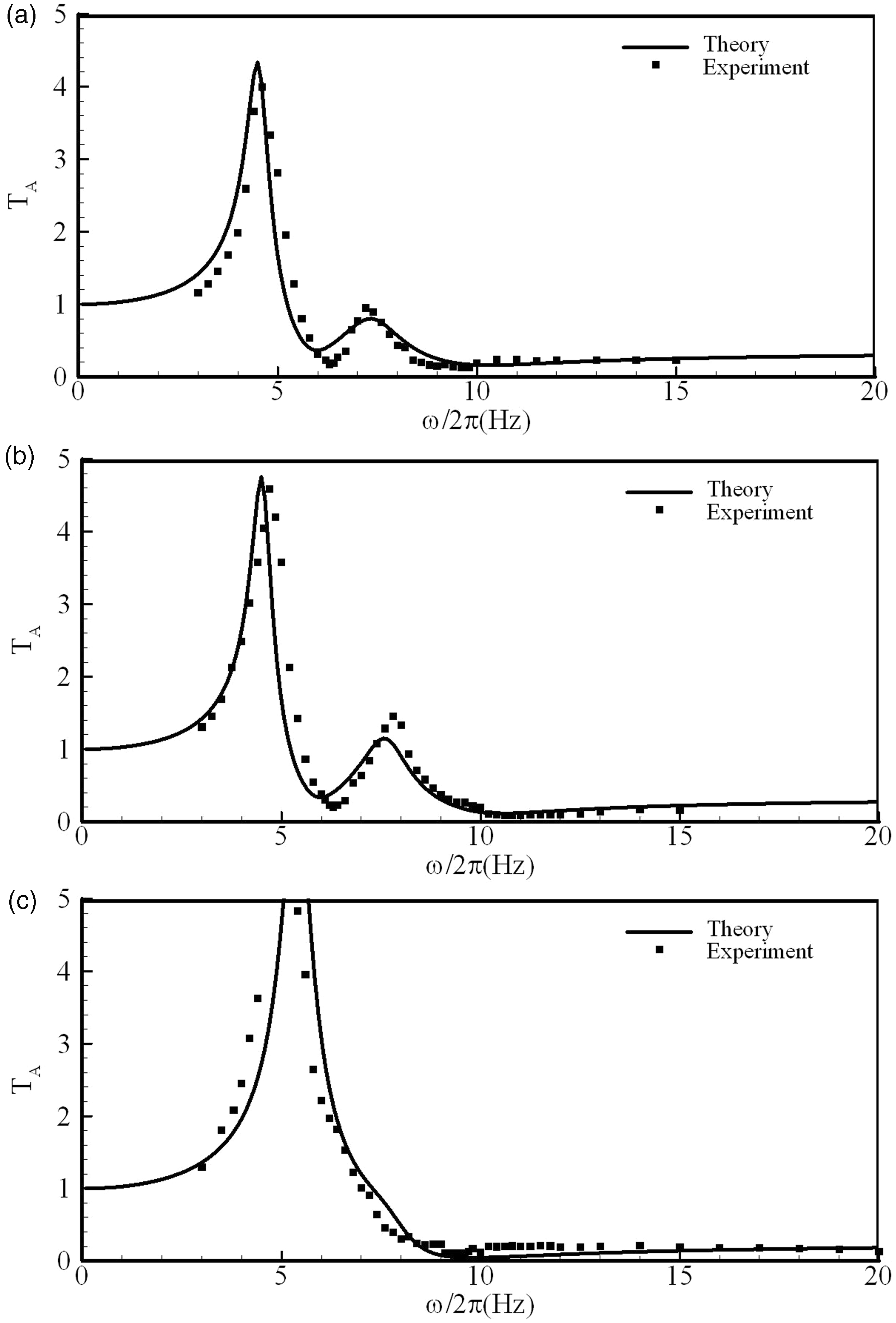
In a series of experiments, values of were adjusted to change the anti-resonance frequencies , . The response of TDOFFVI under the sine excitations with a series of frequencies (sine sweep) was measured. The experiment for each frequency was repeated three times and the force transmissibility obtained at three times was averaged. Thus the force transmissibility of TDOFFVI at a series of frequencies was given. Figure 12 shows the variations of the TDOFFVI force transmissibility with excitation frequency for different anti-resonance frequencies (for both experiment and theory). For the calculation of force transmissibility of the TDOFFVI theoretically, the damping coefficients , have to be available. It is difficult to obtain the values of , theoretically. In this paper, the values of , are tuned to match the theoretical amplitudes with the experimental one. For different cases, the values of , obtained by matching are not the same. However, they are confined to the range from 0.065 to 0.1. For all studied cases, the variation trend of the force transmissibility with excitation frequency given by theoretical analysis generally agrees with that observed in experiments and the two anti-resonance frequencies predicted by theory can roughly match the experimental results.
Variation of force transmissibility with excitation frequency for theoretical and experimental results. (a), (b) , , , (c), .
6. Conclusions
A novel two-degree-of-freedom floating vibration isolation system has been developed based on an anti-resonance mechanism. It was designed with two tunable anti-resonance frequencies able to attenuate two frequency vibrations. The technique of adjusting anti-resonance frequencies was addressed and the characteristics of the isolation system were theoretically analyzed. Further, the optimal design of the system was discussed where the effect of the ratios of , and the damping coefficients of the system on the isolation performance were stated. The TDOFFVI can also be employed to cover single-frequency vibration problems with the two anti-resonance frequencies tuned to be identical. In numerical comparisons, the TDOFFVI greatly outperforms a previous SDOFFVI, due to its double-layer isolation design. An actual experimental prototype was built and tested to verify the vibration isolation performance. A series of experiments were carried out for three cases. The theoretical and experimental results were generally well in agreement.
Footnotes
Funding
This work was supported by the National Natural Science Foundation of China (grant numbers 11272116 and 1102062).
References
1.
BraunD (1982) Development of antiresonance force isolators for helicopter vibration reduction. Journal of the American Helicopter Society27(4): 37–44.
2.
CarrellaABrennanMJKovacicIWatersTP (2009) On the force transmissibility of a vibration isolator with quasi-zero-stiffness. Journal of Sound and Vibration322: 707–717.
3.
ChatterjeeS (2008) On the design criteria of dynamic vibration absorbers for controlling friction-induced oscillations. Journal of Vibration and control14(3): 397–415.
4.
DesjardinsRAHooperWE (1980) Antiresonant rotor isolation for vibration reduction. Journal of the American Helicopter Society25(3): 46–55.
5.
Flannelly WG (1967) Dynamic anti-resonant vibration isolator. US Patent 3,322,379.
6.
Frahm H (1911) Device for damping vibrations of bodies. US Patent 989,958.
7.
Goodwin AJH (1965) Vibration isolators. US Patent 3,202,388.
8.
GongDZhouJSSunWJ (2013) On the resonant vibration of a flexible railway car body and its suppression with a dynamic vibration absorber. Journal of Vibration and Control19(5): 649–657.
9.
Halwes DR (1980) Vibration suppression system. US Patent 4,236,607.
10.
Hodgson DA and Duclos TG (1991) Vibration isolator with electrorheological fluid controlled dynamic stiffness. US Patent 5,029,823.
11.
IbrahimRA (2008) Recent advances in nonlinear passive vibration isolators. Journal of Sound and Vibration314: 371–452.
12.
Jones PJ and Downing MW (1993) Adaptive fluid mount. US Patent 5,197,692..
13.
LiYLXuDLFuYMZhouJX (2011) Stability analysis and chaotification of vibration isolation floating raft systems with time-delayed feedback control. Chaos21: 033115–033115.
14.
LiuCRXuDLJiJF (2012) Theoretical design and experimental verification of a tunable floating raft vibration isolation system. Journal of Sound and Vibration331: 4691–4703.
15.
LouJJZhuSJHeLYuX (2005) Application of chaos method to line spectra reduction. Journal of Sound and Vibration286: 645–652.
16.
PlooyNFHeynsPSBrennanMJ (2005) The development of a tunable vibration absorbing isolator. International Journal of Mechanical Sciences47: 983–997.
17.
RitaADMcGarveyJHJonesR (1978) Helicopter rotor isolation evaluation utilizing the dynamic antiresonant vibration isolator. Journal of the American Helicopter Society23(1): 22–29.
18.
ScarboroughLHRahnCDSmithEC (2012) Fluid composite tunable vibration isolators. Journal of Vibration and Acoustics134: 011010–1–011010–7.
19.
ShenYJWangLYangSPGaoGS (2013) Nonlinear dynamical analysis and parameters optimization of four semi-active on-off dynamic vibration absorbers. Journal of Vibration and Control19: 143–160.
20.
Smith MR and Stamps FB (1998) Vibration isolation system. US Patent 5,788,029.
21.
WenGLLuYZZhangZYMaCSYinHFCuiZ (2009) Line spectra reduction and vibration isolation via modified projective synchronization for acoustic stealth of submarines. Journal of Sound and Vibration324: 954–961.
22.
YilmazCKikuchiN (2006a) Analysis and design of passive band-stop filter-type vibration isolators for low-frequency applications. Journal of Sound and Vibration291: 1004–1028.
23.
YilmazCKikushiN (2006b) Analysis and design of passive low-pass filter-type vibration isolators considering stiffness and mass limitations. Journal of Sound and Vibration293: 171–195.
24.
YuXZhuSJLiuSY (2007) A new method for line spectra reduction similar to generalized synchronization of chaos. Journal of Sound and Vibration306: 835–848.